1
Gateway Installation manual
READ THIS MANUAL ATTENTIVELY BEFORE
STARTING UP THE UNIT. DO NOT THROW IT AWAY.
KEEP IT IN YOUR FILES FOR FUTURE REFERENCE.
IMPROPER INSTALLATION OR ATTACHMENT OF
EQUIPMENT OR ACCESSORIES COULD RESULT IN
ELECTRIC SHOCK, SHORT-CIRCUIT, LEAKS, FIRE OR
OTHER DAMAGE TO EQUIPMENT. BE SURE ONLY TO
USE ACCESSORIES MADE BY DAIKIN THAT ARE
SPECIFICALLY DESIGNED FOR USE WITH THE
EQUIPMENT AND HAVE THEM INSTALLED BY A
PROFESSIONAL.
IF UNSURE OF INSTALLATION PROCEDURES OR
USE, ALWAYS CONTACT YOUR DAIKIN DEALER FOR
ADVICE AND INFORMATION.
INTRODUCTION
Thank you for purchasing the Gateway EKBMSMBA or
EKBMSBNA Kit. This Gateway will enable you to communicate
with your chiller or chillers through a Building Management
System (BMS) or other supervisory system. More specifically, it
functions as a translator between the BMS or supervisory system
and the address cards of the actual chiller or multiple chillers.
As such, the Gateway ensures the connection of all address cards
— and thus also of the chillers — with systems that can
communicate in Modbus or BACnet protocol.
YOUR GATEWAY KIT
The kit you have just purchased consists of:
■1 Gateway
■1 PC diskette with an MS-DOS-formatted program for the initial
configuration of the Gateway
■a cable terminal (resistor)
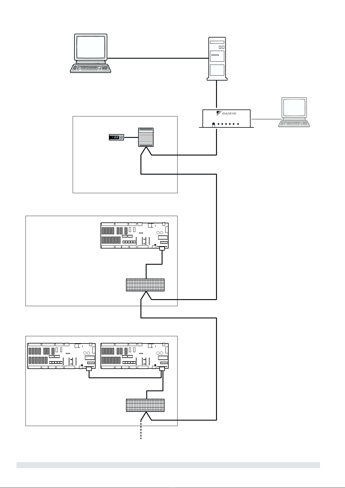
GENERAL OVERVIEW OF THE SYSTEM
Different parts of the communication network
The communication network consists of two major players:
■The Building Management System or supervisory system.
■The chiller or multiple chillers.
The BMS or other supervisory system is able to communicate with
the chillers through two communication devices:
■The Gateway, a separate device that functions as a translator
between the Modbus/BACnet signals of the BMS or
supervisory system and the protocol used by the chiller’s
address card.
■The address card, a card placed on each PCB of the chiller or
a module placed inside the switchbox, depending on the range
of the chiller. It identifies the chiller. The Gateway can
communicate with up to 16 address cards using the Modbus-
Jbus protocol or up to 8 address cards using the BACnet
protocol. Mind that each PCB needs one address card!
(Refer to figure 1.)
DESCRIPTION OF THE GATEWAY
Technical data
■Intel 8032 microprocessor, 12 MHz
■240Vac factory standard power supply (can be changed into
24Vac or 120Vac)
■resident program, EPROM, 64 KB
A front view: Keys and LED’s
Key Purpose
print out No function
reset Press this key to reset the Gateway. It will restart the internal
configuration and external inquiry process of the address cards
LED Colour Indication
line yellow Power supply on
alarm 1 red Error in the configuration stored in the buffered RAM
alarm 2 red Malfunction in the communication between thegateway and the
address card, probably due to an inconsistency with the initial
configuration
rx green Communication OK (blinking)
tx green Communication OK (blinking)
A rear view: Connectors
The rear panel of the gateway has the following series of
connectors:
Connector name Connects to… Type
modem BMS/supervisory system with RS-232 standard 9 standard way male
RS-422/485 BMS/supervisory system with RS-485 standard 9 standard way female
config. Configuration PC 9 standard way male
Carel Net. Address cards with RS-485 standard 9 standard way female
fuse
line
print out
alarm 1
alarm 2
rx
tx
reset
Gateway
config.
Carel Net. relay fuse
cod.
modem
rs422/485
EKBMSMBA
EKBMSBNA