Nidac DT1 User manual

DT1Series 2
SINGLE CHANNEL TALKING DIALLER
INSTALLATION MANUAL 2nd EDITION.

NEW FEATURES
•Simplified memory layout allowsfor quicker and easier programming.
•Phone line now uses RJ12 with standard connections.
NOW AVAILABLE
DRI24 -interface to allow the DT1to be used with 24V D.C. power supplies,
convenient for use with Fire Panels.
Note that the CH2, CH3, CH4 & CH5 inputs and the 2 relay outputs have no
function when the DRI24 is used with a DT1.
SPECIAL NOTE TO NEW ZEALAND CUSTOMERS
1. Alarm equipment or sensors etc. connected to the inputs shall meet the
requirements of the New Zealand Electricity Act 1993 and its associated codes
of practice.
2. The dialler shall only be powered by an approved power source.
3. The preferred method of dialling is to use DTMF tones as this is faster and more
reliable than pulse (decadic) dialling. If for some reason you must use decadic
dialling, the numbers must be entered using the following translation table as
this dialler does not implement the New Zealand “Reverse Dialling” standard.
Number to be dialled: 0 1 2 3 4 5 6 7 8 9
Number to program in dialler: 0 9 8 7 6 5 4 3 2 1
Note that where DTMF dialling is used, the numbers should be entered
normally.

DT1 Series 2 -SINGLE CHANNEL TALKING DIALLER
i
TABLE OF CONTENTS PAGE
PRODUCT FEATURES.........................................................................................1
DIALLER OPERATION .........................................................................................2
Power up...........................................................................................................2
Activation..........................................................................................................2
Call Sequence...................................................................................................2
Cancelling the Dialler ........................................................................................3
SPECIFICATIONS.................................................................................................3
INSTALLATION.....................................................................................................4
PROGRAMMING...................................................................................................6
Phone Numbers................................................................................................8
Dialling Mode....................................................................................................8
Message Repeat Time......................................................................................8
Maximum Dialling Attempts...............................................................................9
Key Switch Input Polarity...................................................................................9
Alarm Input Polarity...........................................................................................9
Alarm Input Mode..............................................................................................9
Slave / Latching Mode.....................................................................................10
Cut Off Message After DTMF ..........................................................................10
Shut Down Code.............................................................................................10
User Message.................................................................................................11
REPLAY OF PROGRAMMED DATA...................................................................11
Blank Memory Indication.................................................................................11
ERROR INDICATION..........................................................................................12
Program / Display Errors.................................................................................12
Operational Errors...........................................................................................12
LIST OF FIGURES PAGE
Figure 1: The DT1 with its outer cover removed.................................................4
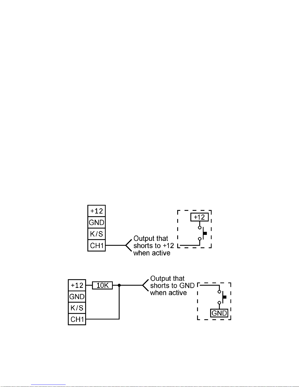
Figure 2: Connecting an output that drives high to the DT1..............................5
Figure 3: Connecting an output that drives low to the DT1...............................5

DT1 Series 2 INSTALLATION MANUAL
1
PRODUCT FEATURES
•A-tick approved equipment.
•15 second user recordable voice message.
•1alarm input.
•Key Switch input to enable/disable the alarm input.
•Programmable polarity on alarm and key switch inputs.
•Non volatile memory stores programmed data and voice message for 10 years
without power.
•6 user programmable phone numbers.
•Up to 6 dialling attempts at communicating an alarm condition.
•Remote shutdown of dialler via user programmable shutdown code (1 to 7 digits)
on DTMF phones.
•Fully programmable through the on board keypad.
•Programmed information can be verified by replaying it on the 7-segment display
(numeric data) or through the on board speaker (recorded voice).
•50 millisecond debounce time on all inputs.
•Failure and Error code indication.

DT1 Series 2 INSTALLATION MANUAL
2
DIALLER OPERATION
POWER UP
When power is applied to the DT1 it will perform a self test, then flash the digit 1five
times on the 7 segment display. While the DT1 is performing the self test but before
the 1is displayed, the 7 segment display may show anything, this is normal.
ACTIVATION
The DT1 can be programmed to trigger from either a positive or negative going alarm
source. The key switch input can be used to cancel an alarm call and/or disable the
alarm input.
CALL SEQUENCE
Once the DT1 has been triggered, it will seize the phone line and hold it for 3 seconds
to clear any calls that may be in progress. It then waits a further 3 seconds to get a
line out before dialling a number. After dialling a phone number the DT1 plays the
user message. The DT1 repeats the user message for the programmed time and only
finishes the call at the end of a message repetition or until cancelled.
After receiving a trigger the DT1 will attempt up to 6 diallings to communicate the
alarm information (the maximum number of dial attempts can be set from 1 to 6, refer
to the MAXIMUM DIALLING ATTEMPTS section on page 9). Each programmed
phone number will be called in order until either the dialler has been shut down, or the
maximum number of dial attempts have been made. If there are less phone numbers
programmed than the max dial attempts, then the DT1 will redial the first number
followed by the second and so on, until the maximum number of dial attempts have
been made.
During the dialling of an alarm the DOT on the display will flash at a rate of twice per
second. If after dialling the maximum number of attempts the dialler has not been
cancelled, the DOT will remain on until the K/S (key switch) input state is changed
(dialler is changed between “Away/On” and “24 hour” mode) or the DT1 makes a
successful call after being triggered again. When the dialler is shutdown a “WARBLE”
sound indicating shutdown is heard over the phone line and the display dot will go off.
Should the DT1 be unable to attempt any calls because it has not been programmed
with enough information, it will display error number 5 (no phone numbers in memory)
on the seven segment display.

DT1 Series 2 INSTALLATION MANUAL
3
CANCELLING THE DIALLER
The dialler can be cancelled by one of three methods. These are, remote shutdown
over the phone line using the programmed shut down code, local cancel by the key
switch or by removing the alarm input (this last method will only work if the alarm input
has been selected to operate in the slaved mode). Once the dialler has been
cancelled it will not make any more calls until it receives another alarm trigger.
The remote shutdown of the dialler can be performed by anyone the dialler calls to
report an alarm. To cancel the dialler simply enter the programmed shut down code
(default = digit number 3) on a DTMF (tone) phone while the message is playing.
Note shutting down of the dialler does not shut down any local alarm, even if this is
the trigger source.
Note the dialler should be tested regularly to ensure that it is operating correctly.
SPECIFICATIONS
CONNECTIONS -4 screw terminals.
ALARM INPUT -User definable trigger polarity, can operate in latched or
slaved mode.
KEY SWITCH INPUT -User definable polarity. Application of the correct polarity
will enable the alarm input.
POWER SUPPLY -11.5 to 14V DC @ 150mA (max).
TELECOM LINE -Single RJ12socket (Western Jack). Supplied with lead
to suit a Telecom Mode 3 phone socket or TH3 adaptor.
COMMUNICATION
DIALLING FORMAT -Selectable as Decadic (pulse) or DTMF (tone).
USER MESSAGE -15 seconds for alarm and name and/or address.
MECHANICAL
DIMENSIONS -165mm width x 135mm depth x 45mm height.
WEIGHT -330 grams with cover (230 grams without).

DT1 Series 2 INSTALLATION MANUAL
4
INSTALLATION
All connections to the DT1 from an external alarm source are made via the row of
screw terminal connectors found on the circuit board. To gain access to the circuit
board, the outer cover will have to be removed. To do this, unscrew the two outer
screws on the under side of the DT1 (do not unscrew the centre screw) the cover will
now lift off.
To mount the DT1 the TEB dialler mounting bracket is available.
Figure 1: The DT1 with its outer cover removed.
DT1 Series 2 INSTALLATION MANUAL
5
There are 4 terminals on the DT1 board, of these 2 are power inputs, 1 is the key
switch input and 1 is the alarm input. The use of each terminal is described below.
+12 The positive input for the power supply (11.5 to 14V D.C.).
GND The negative (ground) input for the power supply.
K/S The key switch input. This input is driven in the same manner as the alarm
input below. When active, the key switch input puts the DT1 into “Away/On”
mode [the default setting requires +5 to 15V DC on K/S for “Away/On” mode].
CH1 This is the alarm input. The input is held low via an internal pull down resistor to
GND. The input can be put into its alarm state by either applying voltage to it or
removing voltage from it, depending upon the configuration of the input’s
polarity (for further information on input polarity refer to the ALARM INPUT
POLARITY section on page 10). To trigger the input from a source that only
drives low (eg. an Open Collector output or a normally open switch to GND) the
input will have to be pulled up to the positive voltage rail via a 10K resistor as
shown in Figure 3 below [the default setting requires +5 to 15V DC on CH1 to
trigger the dialler].
Figure 2: Connecting an output that drives high to the DT1.
Figure 3: Connecting an output that drives low to the DT1.

DT1 Series 2 INSTALLATION MANUAL
6
PROGRAMMING
All programming of the DT1 is done via the keypad on the unit with confirmation of
programmed data being given on the seven segment display as it is entered. The
internal speaker will give a short beep to indicate when a key has been pressed.
The user voice message is recorded by speaking into the microphone located on the
front of the unit. The message may be replayed through the on board speaker.
Programming of the DT1 is accomplished by first pressing the #key, a “P” will appear
on the display to indicate programming, next is a single or double digit entry identifying
the memory number, followed by a code of variable length depending on the memory.
Termination of programming is accomplished by pressing the #key, or by entering
the maximum number of digits for the memory number being programmed.
All key presses must be done within 10 seconds of each other or all information so
far programmed into the currently open memory will be lost. When this occurs the
speaker sounds a “BLARP” and an error 2 is displayed (refer to the ERROR
INDICATION section on page 12).
Programming of memories 70 to 9require the program link to be ON.
Note that the program link does not have to be removed for the dialler to operate.
The format for programming is
#<memory><code> #for memories 1 to 8.
or
#<memory><voice input> #for memory 9.

DT1 Series 2 INSTALLATION MANUAL
7
Where <memory> is one of the following numbers:
1First phone number (16 digits max)
2Second phone number (16 digits max)
3Third phone number (16 digits max)
4Fourth phone number (16 digits max)
5Fifth phone number (16 digits max)
6Sixth phone number (16 digits max)
70 Dialling mode (1 digit)
71 Message repeat time (3 digits)
72 Maximum dialling attempts (1 digit)
73 Key Switch polarity (1 digit)
74 Alarm input polarity (1 digit)
75 Alarm input mode (1 digit)
76 Slave / latching mode (1 digit)
77 Cut off message after DTMF (1 digit)
8Shutdown code (7 digits max)
9User message (voice data, 15 seconds)
When accessing any of the above <memories> for programming an “A” is displayed to
show that you have ACCESS to the memory location. After pressing the first digit of a
two digit memory ‘n’ will be displayed to indicate another digit is required. When all of
the code digits have been entered or a second #is pressed then a “WARBLE” sound
is heard and a “[” will be displayed for 1 second indicating that the memory is now
CLOSED.
<code> validity is dependent upon the <memory> being accessed and is described in
detail on the following pages.

DT1 Series 2 INSTALLATION MANUAL
8
PHONE NUMBERS
<memories 1-6> The code is the actual TELEPHONE NUMBER being entered and
may be up to 16 digits in length including pauses, which are entered with the *nkey
combination, where the nrefers to a key from 0 to 9 indicating the length of the pause
in seconds. For special purposes the DTMF tones for the # and * may be entered by
using the *# and ** key combinations respectively. The memory is closed by
either pressing the #key or by entering the maximum 16 digits for the telephone
number. To erase a phone number refer to the BLANK MEMORY INDICATION
section on page 12.
Example: #1 3456789#
programs 3456789 as phone number 1.
Example: #5 0*35554938#
programs a 0, a 3 second pause and 5554938 as phone number 5.
[default is no phone numbers programmed]
DIALLING MODE [Requires program link ON]
<memory 70> This memory is used to select whether Decadic or DTMF dialling is to
be used.
0=Decadic (Pulse) dialling.
1=Normal DTMF (Tone) dialling [default].
2=Slow DTMF (Tone) dialling. This selection may be necessary when using
the DT1 with some PABX systems.
MESSAGE REPEAT TIME [Requires program link ON]
<memory 71> This memory is used to set how many seconds the message is
repeated for over the phone line. Note that repetition cycle will only end at the end of
the recorded message.
1 -199 =Number of seconds the message is repeated for [default = 60].

DT1 Series 2 INSTALLATION MANUAL
9
MAXIMUM DIALLING ATTEMPTS [Requires program link ON]
<memory 72> This memory is used to select the maximum number of phone calls
that will be made each time the DT1 is triggered.
Note this is not how many times it will dial each phone number programmed
1 -6 =Max number of dialling attempts to be made in total [default = 6].
KEY SWITCH INPUT POLARITY [Requires program link ON]
<memory 73> This memory is used to select what voltage is required on the K/S
terminal to put the dialler into “Away/On” mode.
0=Input at ground puts the dialler in “Away/On” mode, input at +5 to 15V
DC puts the dialler in 24 Hour Mode.
1=Input at +5 to 15V DC puts the dialler in “Away/On” mode, input at
ground puts the dialler in 24 Hour Mode [default].
ALARM INPUT POLARITY [Requires program link ON]
<memory 74> This memory is used to select what voltage is required on the CH1 to
trigger an alarm dial out on the DT1.
0=Transition to ground for Alarm.
1=Transition to +5 to 15V DC for Alarm [default].
ALARM INPUT MODE [Requires program link ON]
<memory 75> This memory is used to select whether the status of the key switch
input affects whether the alarm input is active.
0=The key switch input must be active (dialler in “Away/On” mode) for the
alarm input to work.
1=The alarm input is always active [default].

DT1 Series 2 INSTALLATION MANUAL
10
SLAVE / LATCHING MODE [Requires program link ON]
<memory 76> This memory is used to select whether the alarm input must remain
triggered for the dialler to complete its dialling sequence.
0=Slave mode. In slave mode the dialler will dial out when the alarm input
is triggered and stop dialling as soon as the trigger is removed.
1=Latching mode. In latching mode, only a momentary trigger is required
to start the dialler (to stop the dial sequence refer to the CANCELLING
THE DIALLER section on page 3) [default].
CUT OFF MESSAGE AFTER DTMF [Requires program link ON]
<memory 77> This memory is used to select whether the dialler stops playing the
alarm message once it receives a valid DTMF digit over the phone line. The reason
why the message is usually stopped once a DTMF digit has been received is to
minimise any errors in detecting the correct shutdown code.
Note that if there is no shutdown code programmed the message will not be stopped
when a DTMF digit is received.
0=The dialler does not stop the message after receiving a DTMF digit.
1=The dialler stops the message after receiving a DTMF digit [default].
SHUT DOWN CODE [Requires program link ON]
<memory 8>The shut down code may be between 1 and 7 digits in length and is used
to acknowledge an alarm call. When the dialler has called a person, they can shut the
dialler down by entering this code on a standard DTMF (tone) phone while the alarm
message is playing, the dialler will acknowledge the code with a warble sound, hang
up and not make any more calls. If this memory is blank, the dialler cannot be shut
down remotely and it will make the maximum number of calls unless cancelled locally.
Example: #8 2478# stores 2478 as the shut down code.
Note shutting down the dialler will not cancel any local alarms.
[default = 3 (digit number 3)]

DT1 Series 2 INSTALLATION MANUAL
11
USER MESSAGE [Requires program link ON]
<memory 9>The data stored for this memory is the recorded voice data for the
dialler’s alarm and location message.
To record a message press #9 then speak into the microphone at a distance of
about 15cm (6 inches). Press # at the end of the message to stop recording. While
the DT1 is recording, a moving pattern is displayed in the lower half of the display.
When recording stops, a “WARBLE” sound is heard and a “[” is displayed for 1
second. Recording stops after 15 seconds or when the #key is pressed, whichever
occurs first.
REPLAY OF PROGRAMMED DATA
Programmed data can be replayed for confirmation simply by pressing the *, a “d”
will appear on the display to indicate displaying, followed by the memory number (1
to 9). The contents of memories 1 to 8 will appear on the 7 segment display at
intervals of 1 digit per second. When replaying a phone number, a pause will be
displayed as a “P” followed by the number representing how many seconds the pause
is for, a hash (#) as “x” and a star (∗) as “o”. When replaying memory 9, the recorded
voice data will be replayed through the speaker.
BLANK MEMORY INDICATION
If you display a memory location that is empty, then a “b” will appear on the display. A
“b” is also displayed when you deliberately erase a memory location. Only the phone
number and shut down code memories can be blank.
To erase a memory location simply open the memory location then close it immediately.
eg. #1# will erase the phone number 1 memory.

DT1 Series 2 INSTALLATION MANUAL
12
ERROR INDICATION
If an error is made during the programming of data then the speaker will sound a
“BLARP” and an “E” + nwill flash 5 times on the display, where nis the error number
as explained below. When the display has ceased flashing, the memory may be
reprogrammed correctly. Error codes are described in detail below.
PROGRAMMING ERRORS
0Memory Access denied. Memory chosen is invalid or program link is off.
1First key pressed was not a *or #.
2Too slow entering data, information is lost. When programming close with a #.
3Value entered is out of range for selected memory.
4Insufficient digits entered for selected memory.
OPERATING ERRORS
5No phone numbers in memory. Program in a phone number.

DT1 Series 2Instruction Book.doc 26/09/03 Revision 2
INSTALLED BY:
FOR SERVICE PHONE:
CUSTOMER:
PHONE NO. 1 ( )PHONE NO. 2 ( )
PHONE NO. 3 ( ) PHONE NO. 4 ( )
PHONE NO. 5 ( ) PHONE NO. 6 ( )
EQUIPMENT ALARM MESSAGE
100%
NIDAC SECURITY PTY. LTD. A.B.N. 49 004 933 242
MANUFACTURERS OF SECURITY EQUIPMENT
2 CROMWELL STREET
BURWOOD, VICTORIA TEL: (03) 9808 6244
AUSTRALIA 3125 FAX: (03) 9808 9335
Table of contents


