Nidac Presco 2 Series User manual
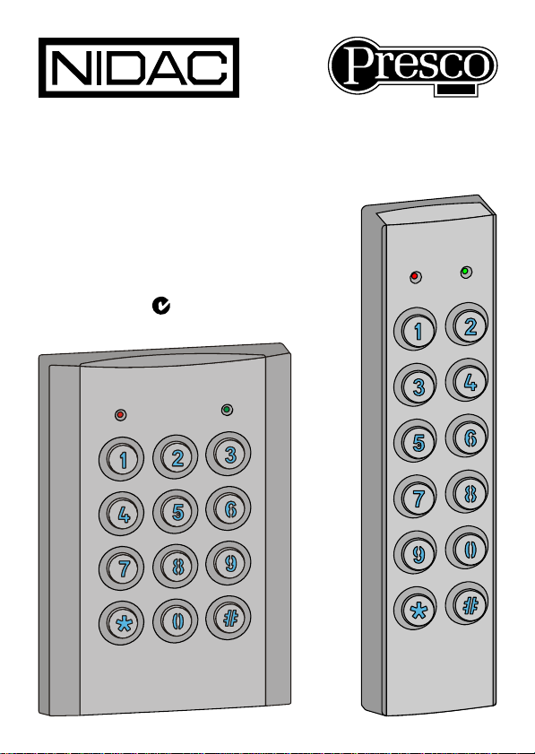
VR43 & VR62
Series 2
Vandal and Weather
Resistant Keypads
N761

i
TABLE OF CONTENTS PAGE
Features.................................................................................1
Package Contents.................................................................1
Specifications .......................................................................2
VR43.................................................................................2
VR62.................................................................................3
Wires......................................................................................4
Installation.............................................................................5
Using the VR keypads with Presco™..................................6
VR to PAC1/PAC2 wiring diagram....................................7
VR to KC2, KC6 & PDA wiring diagram............................7
Using the VR keypads with Wiegand..................................8
VR to Wiegand wiring diagram..........................................8
Options..................................................................................9
General Options................................................................9
Wiegand Options.............................................................10
Presco™ Options............................................................12
Setting the options via the VR keypad ............................13
Warranty..............................................................................14

1
FEATURES
Suitable for indoor and outdoor usage.
Durable and stylish metal keypad construction (satin chrome
plated zinc die cast).
8 to 26 Volt D.C. operation.
Vandal Resistant.
Weather Resistant (IP67).
Outputs Presco™ and Wiegand data.
Blue LED Backlighting on keys standard.
Compatible with all Nidac Presco decoders.
Fully configurable for custom Wiegand modes.
Operating temperature range of -20ºC to 70ºC.
36 month (3 year) manufacturer’s warranty.
PACKAGE CONTENTS
Included in the package for your VR keypad is:
1 x VR43 or VR62 keypad.
1 x Installation manual (this document).
1 x VR keypad cable with rubber sealing boot.
1 x Hex Allen key to remove screw for fascia.
1 x Mounting template.
If any of these items are missing please contact your supplier.

2
SPECIFICATIONS
Voltage: 8V to 26V D.C. recommended.
7V to 30V D.C. absolute limits.
Current: 60mA max @ 7V D.C. (without backlighting)
110mA max@ 7V D.C. (with backlighting)
35mA max @ 12V D.C.(without backlighting)
70mA max @ 12V D.C.(with backlighting)
30mA max @ 24V D.C.(without backlighting)
55mA max @ 24V D.C.(with backlighting)
Ingress Protection Rating: IP67
VR43
Weight: 780 grams (including cable).
Dimensions: 132mm x 92mm x 20mm (H x W x D).

3
VR62
Weight: 620 grams (including cable).
Dimensions: 161.7mm x 45mm x 23mm (H x W x D).

4
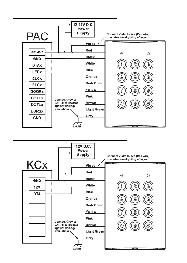
WIRES
There are 12 wires for the VR keypads, not all will be needed for
each installation. The unused wires should always be
terminated and left unconnected.
Black 0V (Ground).
Red +12V to +24V D.C.
White DTA (Presco™ data line).
Dark Green D0 (Wiegand Data 0).
Yellow D1 (Wiegand Data 1).
Violet +3V to +24V D.C. Backlighting control.
Blue Green LED control wire, +3V to +24V active.
Orange Red LED control wire, +3V to +24V active.
Brown Buzzer control wire, 0V active.
Light Green Green LED control wire, 0V active.
Pink Presco™/Wiegand mode select wire, 0V active
for Wiegand mode.
Grey Chassis Earth connection.
NOTE: The Blue, Orange, Brown, Light Green and Pink wires
can be programmed to control different functions. Refer to the
Options section on page 8.
IMPORTANT: When using the VR43 or VR62 in an area subject
to static discharges the chassis of the VR keypad should be
connected to EARTH via the grey wire. It is highly
recommended that this always be done no matter what the
environment.
5
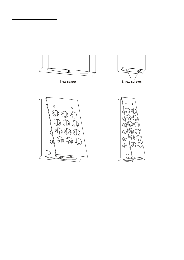
INSTALLATION
1. Using the supplied template mark out the location of the
mounting screws and the cable exit. Drill out all points as
necessary.
2. Using the supplied key remove the hex allen screw(s) at the
bottom of the keypad that secure the fascia to the chassis.
3. Swing the fascia up from the bottom and it will unhook at the
top allowing access to the mounting screw holes.
4. Attach the supplied cable by plugging in the connector (you
may need to use a screw driver to push the connector
around the edges to ensure it is in firmly). Note that it is
designed to be inserted in one way only, however use of
excessive force could allow it to be inserted wrongly so
check the guide locators match before inserting.
5. Slide the rubber boot down the cable and press the first
flange into the hole and leaving the second flange on the
outside of the keypad. Make sure that it sits neatly in all
places to ensure a correct seal.
6. Mount the keypad and reverse steps 2 & 3 to reattach the
fascia to the keypad chassis.

6
USING THE VR KEYPADS WITH PRESCO™
The VR43 & VR62 can be used to perform all the functions of a
standard Presco PRE keypad. The only difference in operation
is the use of the #key instead of the Ekey.
The #key is a dual purpose key. When it is pressed as the first
key in a code sequence it generates a #, when pressed as a
subsequent key it then becomes the Ekey.
Should it be necessary to generate a # in the middle of a code
sequence then you must press and hold down the *key, press
the #key then release both keys.
To use the keypad in Presco™ mode, press the code then the
#key. The keypad can be set up to automatically send the
code after a given number of key presses by setting memory
007 (refer to the OPTIONS section on page 8).
Example Code Sequences
PRE sequence VR equivalent
1. * 000 1E* 000 1#
2. 1234 E1234 #
3. # 000 E# 000 #
Remember to press #after the code to send it unless memory
007 has been set to auto send after a given number of keys.
7
VR TO PAC1 / PAC2 WIRING DIAGRAM
VR TO KC2, KC6 & PDA WIRING DIAGRAM
8
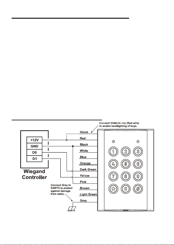
USING THE VR KEYPADS WITH WIEGAND
The VR43 & VR62 can be used with any standard wiegand and
most non standard wiegand controllers. The site (facility) code
can be set from the keypad itself (refer to the Wiegand Options
sections on page 9) and the wiegand data is fully configurable
with up to 64 bits of data. The VR keypads also support
controllers that require burst mode format wiegand.
The Pink wire needs to be connected to 0V (the Black wire) to
set Wiegand output mode (unless the unit has been
programmed to force it into Wiegand mode via memory 005
(refer to the Wiegand Options sections on page 9)
To use the keypad in wiegand (non burst) mode, press the code
then the #key. The keypad can be set up to automatically
send the code after a given number of key presses by setting
memory 007 (refer to the OPTIONS section on page 8).
VR TO WIEGAND WIRING DIAGRAM
Remember to press #after the code to send it unless memory
007 has been set to auto send after a given number of keys.

9
OPTIONS
There are several options that can be set to alter the way in
which the VR keypad behaves. These options fall into the 3
categories of General, Wiegand and Presco™, all of these are
explained below.
The options can be set from either the keypad itself or through
the use of a PIM (series 3 or later) and the PIM-VR software
available from our website http://www.nidac.com in the
downloads section under Presco software. Refer to the help file
supplied with the software for details on how to use the PIM to
set the VR keypad options.
General Options
These options set the functionality of the blue, orange, brown,
light green and pink control wires as well as other options that
are independent of whether the keypad is in Wiegand or
Presco™ mode.
Memory
Number Function Default
Value
000 Blue wire control
(1)
1
001 Orange wire control
(1)
2
002 Brown wire control
(1)
4
003 Light Green wire control
(1)
1
004 Pink wire control
(1)
(2)
2
005 Force Presco or Wiegand mode
(3)
255
006 Key press timeout 10
007 Auto send key count
(4)
0
008 Key presses produce a beep & flash red LED
(5)
255
(1) - Wire control values [Memories 000 to 004]
0 = Nothing controlled. 4 = Buzzer.
1 = Green LED. 5 = Green LED + Buzzer.
2 = Red LED. 6 = Red LED + Buzzer.
3 = Green LED + Red LED. 7 = Green LED + Red LED + Buzzer.
(2) - Pink wire control [Memory 004]
The Pink wire is always used to select Presco or Wiegand mode unless
memory 005 is set to either 101 or 202 (see memory 005, note 3).

10
(3) - Force Presco or Wiegand mode [Memory 005]
101 =Always in Presco mode.
202 =Always in Wiegand mode.
All other values = Mode selected by pink wire.
(4) - Auto send key count [Memory 007]
When this memory is set to a non zero value the VR keypad will
automatically send the data after xkeys have been pressed, where
x=value set for this memory.
Note:In Presco mode the auto send is disabled if the first key pressed is
a *or #.
(5) - Key press audio & visual confirmation [Memory 008]
101 =Key presses cause the red LED to flash but no beep is sounded.
151 =Key presses cause a beep to sound but the red LED doesn’t flash.
202 =Key presses provide no visual or audio confirmation. The red LED
doesn’t flash and no beep is sounded.
All other values = Key presses causes a beep to sound and the red LED
to flash.
Wiegand Options
These options set the format of the Wiegand data sent by the
keypad when Wiegand mode is selected. The keypad can send
up to 64 bits of data including a site code up to 32 bits.
Memory
Number Function Default
Value
020 Site Code byte 3 0
021 Site Code byte 2 0
022 Site Code byte 1 0
023 Site Code byte 0 (used for standard 8 bit site code) 1
024 Number of bits in Site Code (0 to 32) 8
025 Number of bits in User Code (8 to 64) 16
026 Number of bits for start parity calculation 12
027 Number of bits for end parity calculation 12
028 Parity polarity
(6)
2
029 Error handling
(7)
255
032 Wiegand burst mode
(8)
255
033 Custom Wiegand total number of bits
(9)
255
034 Send LSB first
(10)
255

11
Memory
Number Function Default
Value
035 Site Code start bit number 255
036 User Code start bit number 255
040 Default Custom Wiegand Pattern byte 7
(11)
255
041 Default Custom Wiegand Pattern byte 6
(11)
255
042 Default Custom Wiegand Pattern byte 5
(11)
255
043 Default Custom Wiegand Pattern byte 4
(11)
255
044 Default Custom Wiegand Pattern byte 3
(11)
255
045 Default Custom Wiegand Pattern byte 2
(11)
255
046 Default Custom Wiegand Pattern byte 1
(11)
255
047 Default Custom Wiegand Pattern byte 0
(11)
255
(6) - Parity Polarity [Memory 028]
0 = Start parity is Even, End parity is Even.
1 = Start parity is Odd, End parity is Even.
2 = Start parity is Even, End parity is Odd (default value).
3 = Start parity is Odd, End parity is Odd.
(7) - Error Handling [Memory 029]
This memory specifies what information is sent via the Wiegand
interface when a code is entered that is too large to be represented by
the current Wiegand format.
E.g. Standard 26 bit Wiegand has a 16 bit user code which allows a
maximum code number of 65535. This memory determines what
happens when a number greater than 65535 is entered.
101 = A code of 0 is sent.
202 = No information is sent, the keypad ignores the input.
All other values = The maximum allowable code number for the current
format is sent (for 26 bit Wiegand this is 65535).
(8) - Wiegand burst mode [Memory 032]
101 =4 bit burst mode, *& #keys enabled.
121 =4 bit burst mode, *& #keys disabled.
202 =8 bit burst mode, *& #keys enabled.
212 =8 bit burst mode, *& #keys disabled.
All other values = Standard non burst mode Wiegand.
(9) - Custom Wiegand total number of bits [Memory 033]
When this memory is set to a value from 8 to 64 it overrides the standard
Wiegand format of start parity followed by site code then user code then

12
end parity and replaces it with a fully customisable format with a total
number of bits (including any parity bits) as specified in this memory.
Setting this memory to a value of less than 8 or greater than 64 will
cause to PIM to use the standard Wiegand format.
Note that using this option requires a high understanding of Wiegand
data. Nidac will only offer limited support for this feature.
(10) - Send LSB first [Memory 034]
101 =LSB of data is sent first for both site and user code.
All other values = MSB of site and user code data sent first.
(11) - Default Pattern bytes [Memories 040 to 047]
When the custom Wiegand format is used by setting memory 033 then
the data in these memories is used to define the value for those bits not
in use by the site code, user code and parity bits. The data used starts
from Bit 0 (LSB) in Default Pattern byte 0 (memory 047), e.g. if the total
number of bits is set to 24 then Default Pattern bytes 2, 1 & 0 are used.
Presco™ Options
These options set how the keypad operates when in Presco™
mode. It is highly unlikely that these options will ever need to be
changed.
Memory
Number Function Default
Value
060 Internal/External mode Presco keypad
(12)
255
061 Process received DTA chars mode
(13)
255
(12) - Internal/External mode Presco keypad [Memory 060]
101 =Internal mode keypad.
All other values = External mode keypad.
Note: When set to internal mode the two button Emergency (*#) and
One Way Arm (##) features are enabled when used with a KC2 or
KC6. This setting has no effect when the unit is being used with any
other Presco decoder (e.g. PAC1 or PAC2).
(13) - Process received DTA chars mode [Memory 061]
101 =Ignore all received DTA chars (keypad will not give beeps, warble,
etc. after final #is pressed).
202 =Make noises for all received valid DTA chars received. The
keypad will generate beeps, warble, etc. for all chars received at
any time and after final # key is pressed.

13
All other values = Keypad will only make beeps, warble, etc. for DTA
chars received after pressing the final # key.
Note: This memory only has an effect when the keypad is in Presco
mode (either through the Pink wire or Memory 005 = 101), in Wiegand
mode all received chars on the DTA line are ignored.
Setting the options via the VR keypad
To set any of the above options the keypad first needs to be
placed into program mode, this is done by the following method:
1. Remove power from the VR keypad.
2. Hold down the 3, 6& 9keys.
3. Reapply power whilst continuing to hold down the keys.
4. Once the red & green LEDs start to flash alternatively to
indicate you are in program mode release the keys.
5. The keypad will remain in program for 5 mins from the last
attempted programming sequence.
Programming a memory
*<3 digit memory number> <1 to 3 digit memory value> #.
Reset all memories to factory defaults
*987654# whilst in program mode.
Exit Program Mode
*999# or wait 5 minutes after last programming attempt.

VR Series 2 Instructions.docx Revision 1.0
WARRANTY
The manufacturer will replace or repair this product if proven to
be faulty (excluding accidental or malicious damage) under the
36 month warranty offered from the date of purchase.
As NIDAC Security Pty. Ltd. or its agents do not perform the
final installation, inspection or training in the use of this product,
they cannot be held liable for injury, loss or damage directly or
consequentially arising from the use or misuse of this product.
The software design of the NIDAC Presco™ is protected
internationally. Design improvement and specification changes
are subject to change without notice. All designs are copyright
protected.
100%
This manual suits for next models
2
Table of contents
Other Nidac Keypad manuals


