Nidac 1 Series User manual

VST43 & VST62
Series 1
Vandal and Weather Resistant
Stand Alone Keypads
N761
Instruction Manual

TABLE OF CONTENTS PAGE
i
1 GENERAL INFORMATION.........................................................1
1.1 Features................................................................................1
1.2 Package Contents.................................................................2
1.3 Specifications........................................................................2
1.3.1 VST43 Dimensions.........................................................3
1.3.2 VST62 Dimensions.........................................................3
2 INSTALLATION..........................................................................4
2.1 Mounting...............................................................................4
2.2 Wiring the VST Keypads.......................................................5
2.2.1 Wire Colours...................................................................5
2.2.2 Lock Wiring.....................................................................6
2.2.3 Auxiliary Wiring...............................................................6
2.2.4 Auxiliary Lock Wiring.......................................................7
2.2.5 Tamper Output................................................................7
2.2.6 Fail Secure Lock Wiring with Tamper Security................8
3 OPERATION...............................................................................9
3.1 LED indication.......................................................................9
3.1.1 Mode LED.......................................................................9
3.1.2 Status LED in Operating Mode......................................10
3.2 Default Codes.....................................................................10
3.3 User Codes.........................................................................11
3.3.1 Managers......................................................................11
3.3.2 Primary Users...............................................................11
3.3.3 Standard Users.............................................................11
3.4 Code Usage........................................................................12
3.4.1 Door Access.................................................................12
3.4.2 Advanced Code Functions............................................12
4 INSTALLER SETTING PROGRAMMING ................................. 13
4.1 Setting 901 – Lock Relay Time............................................14
4.2 Setting 902 – Lock Relay Mode...........................................14
4.3 Setting 903 – REX Input Mode............................................14
4.4 Setting 910 – Auxiliary Mode...............................................14
4.4.1 Auxiliary Input Functions...............................................15

TABLE OF CONTENTS PAGE
ii
4.4.2 Auxiliary Relay Functions..............................................15
4.5 Setting 911 – Auxiliary Relay Time......................................17
4.6 Setting 912 – Auxiliary Lock Relay Mode ............................17
4.7 Setting 913 – Auxiliary REX Input Mode..............................17
4.8 Setting 914 – DOTL Time ...................................................17
4.9 Setting 915 – Auto Relock Enabled.....................................18
4.10 Setting 920 – Backlighting Brightness.................................18
4.11 Setting 921 – Key Press Indication......................................18
4.12 Setting 922 – Key Time Out ................................................18
4.13 Setting 923 – Tamper Sensitivity.........................................19
4.14 Setting 931 – Lockout after invalid codes............................19
4.15 Setting 932 – Lockout Time.................................................19
4.16 Setting 933 – Latching Override enable...............................19
4.17 Setting 934 – Latching Override cancelled by code use ......20
4.18 Setting 935 – Lockout Standard Users via Advanced
Code Function.....................................................................20
4.19 Setting 961 – Code Length..................................................20
4.20 Setting 969 – Reset keypad to factory defaults....................21
4.21 Setting 999 – New installer code.........................................21
5 USER CODE PROGRAMMING ................................................22
5.1 Adding User Codes.............................................................23
5.1.1 Regular Method to Add User Code ...............................24
5.1.2 Search Method to Add User Code ................................24
5.1.3 Bulk Add User Codes Method.......................................25
5.2 Deleting User Codes...........................................................26
5.2.1 Deleting All User Codes................................................26
6 ENABLE/DISABLE INSTALLER CODE...................................27
7 FORGOTTEN INSTALLER OR MANAGER CODE ..................28
APPENDIX A: INSTALLER SETTING SUMMARY........................29
APPENDIX B: USER CODE PROGRAMMING SUMMARY........... 30
APPENDIX C: QUICK SETUP GUIDE...........................................32

1
1 GENERAL INFORMATION
1.1 FEATURES
•Suitable for indoor and outdoor use.
•Durable and stylish metal keypad construction (satin chrome plated
zinc die cast).
•10 to 27 Volt D.C. operation.
•Controls up to 2 doors.
•2 x 2A SPDT relays.
•1 x dedicated REX (Request to EXit) input.
•1 x Auxiliary input.
•REX input can be used with Normally Open or Closed and
Momentary or Continuous switches.
•Choice of fixed or variable length codes of 3 to 8 digits.
•Up to 500 user codes.
•3 levels of user codes.
•Lowest level user codes may be locked out by use of auxiliary input
and/or higher level user codes.
•Built in optical tamper based on IR transmitter and receiver provides
accurate tamper detection.
•Blue backlighting on keys with adjustable brightness.
•Vandal Resistant.
•Weather Resistant (IP67).
•Operating temperature range of -20ºC to 70ºC.
•36 month (3 year) manufacturer’s warranty.

2
1.2 PACKAGE CONTENTS
Included in the package for your VST keypad is:
1 x VST43 or VST62 keypad.
1 x Instruction manual (this document).
1 x VST keypad cable with rubber sealing boot.
1 x Hex Allen key to remove screw(s) for fascia.
1 x Mounting template for both VST43 & VST62.
If any of these items are missing please contact your supplier.
1.3 SPECIFICATIONS
Voltage: Recommended Range: 10V – 27V D.C.
Absolute Range: 7V – 30V D.C.
Current: 100 mA max @ 7V D.C.
75 mA max @ 12V D.C.
40 mA max @ 24V D.C.
Relays: 2 x SPDT, 2A @ 30V D.C.
REX & Auxiliary Inputs Trigger Levels:
Low <= 1.5V D.C.
High => 2.5V D.C.
Input Current = 7mA max.
REX & Auxiliary Inputs Voltage range:
Minimum = 0V
Maximum = 30V D.C.
Tamper Output:
100mA maximum sink current (open collector).
Weight: VST43 770 grams (including cable).
VST62 615 grams (including cable).
Ingress Protection Rating:
IP67

3
1.3.1 VST43 Dimensions
1.3.1 VST62 Dimensions

4
2 INSTALLATION
2.1 MOUNTING
1. Use the supplied template to mark the location of the cable exit and
mounting screws. Drill out all points as necessary.
2. Using the supplied key remove the hex Allen screw(s) at the bottom
of the keypad that secure the fascia to the chassis.
3. Swing the fascia up from the bottom and it will unhook at the top
allowing access to the mounting screw holes.
4. Attach the supplied cable by plugging in the connector (you may
need to use a screw driver to push the connector around the edges
to ensure it is in firmly). Note that it is designed to be inserted in one
way only; however use of excessive force could allow it to be
inserted wrongly so check the guide locators match before inserting.
5. Slide the rubber boot down the cable and press the first flange into
the hole and leaving the second flange on the outside of the keypad.
Make sure that it sits neatly in all places to ensure a correct seal.
6. Mount the keypad and reverse steps 2 & 3 to reattach the fascia to
the keypad chassis.

5
2.2 WIRING THE VST KEYPADS
The VST keypads come with a 100cm long AWG-26 removable 12
conductor cable fitted with rubber boot.
2.2.1 Wire Colours
There are 12 wires for the VST keypads, not all will be needed for each
installation.The unused wires should always be terminated and left
unconnected.
Black 0V (Power Supply -)
Red +V (10V to 27V D.C. Power Supply +)
Dark Green REX (Request to EXit) Input, connect switch between
REX and 0V
White Auxiliary Input, connect switch or door contact between
Auxiliary Input and 0V
Grey Lock Relay N/O
Violet Lock Relay Common
Brown Lock Relay N/C
Yellow Auxiliary Relay N/O
Blue Auxiliary Relay Common
Orange Auxiliary Relay N/C
Pink Tamper Output (Open Collector)
Light Green Chassis Earth connection.
IMPORTANT: When using the VST keypad in an area subject to static
discharges the chassis of the keypad should be connected to EARTH via
the Light Green wire. It is highly recommended that this always be done
no matter what the environment.

6
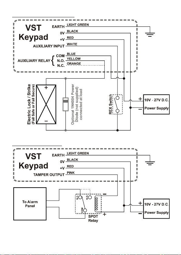
2.2.2 Lock Wiring
2.2.3 Auxiliary Wiring
7
2.2.4 Auxiliary Lock Wiring
2.2.5 Tamper Output

8
2.2.6 Fail Secure Lock Wiring with Tamper Security
This method of wiring the lock ensures that even if the keypad is forcibly
removed from the wall the lock cannot operated by manipulation of the
wiring.
The relay, reset switch and power supply are required to be situated
securely inside where they and their wiring cannot be accessed by
someone on the outside.
The reset button will need to be pressed after power up and also once
any tamper events have been cleared in order to enable the lock to
open.
9
3 OPERATION
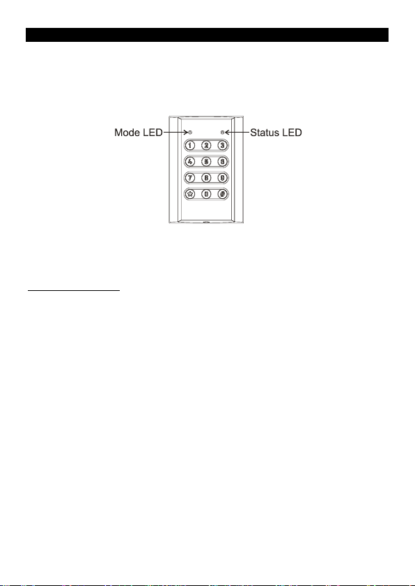
3.1 LED INDICATION
There are 2 LEDs on the VST keypads that are used to indicate different
conditions. Throughout this manual the left LED will be referred to as
the Mode LED and the right as the Status LED.
The symbols used in this manual for the LEDs are:
= off, = on, = flashing single colour and = flashing two
colours alternately, the colour of the LED will also be stated.
3.1.1 Mode LED
The Mode LED is used to indicate the current mode of the keypad; the
various conditions are shown below.
Green
-
Operating mode.
Orange
-
Operating mode with a relay currently latched on.
Red
-
Operating mode with standard user codes locked out.
Red
- Alarm condition (Tamper, DOTL or DFO) in operating mode.
Green
-
Manager Mode.
Green
Orange
-
Installer Mode.
The Mode LED will also flash red briefly each time a button is pressed,
this option can be disabled if desired (refer to setting 921 in the Installer
Programming section on page 18)
10
3.1.2 Status LED in Operating Mode
In operating mode the Status LED indicates the conditions below.
-
Neither relay is currently active.
Green
-
Lock relay is currently active (door unlocked).
Red
-
Auxiliary relay is currently active (door unlocked).
Orange
-
Both Lock & Auxiliary relays are currently active.
Orange
- Single key press registered.
Red
-
Double
key press registered.
What the Status LED indicates in Manager and Installer modes are given
in the relevant sections.
3.2 DEFAULT CODES
There are 3 default codes in the VST keypads that can be used for
setting up and testing the installation.
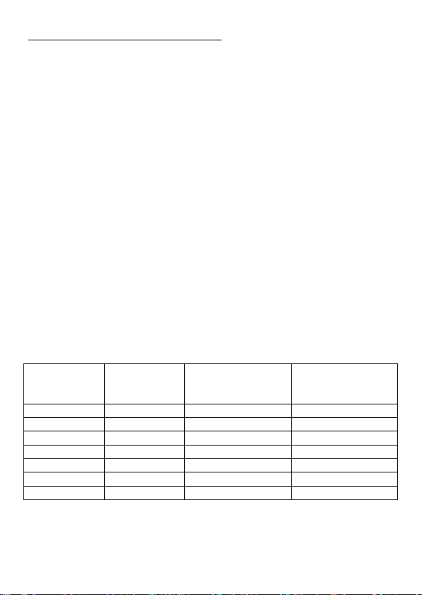
The following table gives the default codes based on the code length
selected in setting 969 of the installer programming section (refer page
21). The factory default setting for code length is 0 (variable code length
from 3 to 8 digits).
Code Length
Setting
Default
Installer
Code
Default Manager
& Lock Test Code Default Auxiliary
Lock Test Code
0
9999
1111
2222
3
999
111
222
4
9999
1111
2222
5
99999
11111
22222
6
999999
111111
222222
7
9999999
1111111
2222222
8 99999999 11111111 22222222
The various default codes will automatically be disabled under the
following conditions:-
The default Installer code is disabled when a new installer code is
programmed.

11
The default Manager code is disabled when a new Manager code is
programmed; it will be enabled again if all programmed manager
codes are deleted.
The default Lock and Auxiliary codes are disabled when any new
code is programmed; they will be enabled again if all programmed
user codes are deleted.
The Default Auxiliary code will also be disabled if the Auxiliary Relay
is not set as Lock Control.
3.3 USER CODES
There are 3 levels of users codes available in the VST keypads to
provide different access levels, all of these code levels can be used for
opening the door. Each code level is described below.
3.3.1 Managers
Mangers are the highest level codes providing the ability to operate the
door(s), perform advanced code functions (refer Advanced Code
functions on page 12) and they allow access to the manager mode to
add and remove user codes.
3.3.2 Primary Users
Primary users are intermediate level codes and can be used to operate
the door(s) and perform advanced code functions (refer Advanced Code
functions on page 12).
3.3.3 Standard Users
Standard users are the lowest level codes and can only be used to
operate the door(s). These codes may also be locked out by the
Auxiliary input and/or the Manager and Primary user codes depending
upon options set in the Installer Setting Programming.

12
3.4 CODE USAGE
User codes can be used to either control the Relays (Door Access) or
perform Advanced Code Functions.
3.4.1 Door Access
The most common use of a code is to control a door lock connected to
the VST keypad. To do this simply enter the code on the VST keypad,
the button will need to be pressed at the end of the code if the system
is set to use variable length codes.
The following examples use the factory default code for the Lock Relay
for different code length settings:-
- When the VST is set for variable length codes (default).
- When the VST is set for code length of 6 digits.
3.4.2 Advanced Code Functions
The following sequences access advanced code functions:-
<manager or primary code> <function key>
when using variable length codes
or <manager or primary code> <function key>
when using fixed length codes
Where <function key> is one of the following options:-
- Unlatch both the Lock and Auxiliary Lock relays (reset both
back to default state, the Auxiliary relay is reset only when it is
set as a second lock control)
- Latch/Unlatch Lock Relay
- Latch/Unlatch Auxiliary Lock Relay (only valid when the
Auxiliary relay is set as a second lock control)
- Lockout Standard User Codes
- Enable Standard User Codes
NOTE: All advanced code functions are disabled by the factory defaults.
To enable these functions for Manager or Primary Users please refer to
sections 4.16 and 4.18.
Examples: The following examples use the default Management code
when the VST is set for variable length codes.
- Locks out Standard User codes.
- Enables Standard User codes.

13
4 INSTALLER SETTING PROGRAMMING
The factory default installer code is 9999.
To enter installer mode press <installer code>
(the final is not required when using fixed length codes)
The keypad will beep 3 times and the Mode LED will alternately flash
Green and Orange ()
To exit installer mode press , the keypad will sound 3 sets of 2
quick beeps.
The VST keypad will remain in Installer mode for 1 minute from the last
key press.
To program a setting use the following sequence:-
<setting number> <new value>
The keypad will respond with a Warble on successful programming or
with a Long Beep for unsuccessful.
In Installer mode the Status LED indicates the conditions below.
- Waiting for the start of a programming or exit sequence.
Green
-
was pressed as first key, waiting for a setting programming
sequence to be completed.
Red
-
was pressed as first key, waiting for an exit command to be
completed.
Red
-
Waiting for the Installer Code to be entered to confirm
programming of setting 961 or 969.
Each valid <setting number>, and its function, is described on the
following pages and a summary is provided in Appendix A on page 29.
All setting numbers are 3 digits long and the first digit is always 9.

14
4.1 Setting 901 – Lock Relay Time
Allowed Values = 0 - 255 Default value = 10
The value for this setting is the time that the Lock relay activates for, in
seconds, when a valid code is used or the REX input is activated.
Note that a value of 0 for this setting will cause the Lock relay to be in
latching mode, making it alternate between open and closed on each
code usage. This will also disable the REX input.
Example: sets the lock relay time to 15 seconds.
4.2 Setting 902 – Lock Relay Mode
Allowed Values = 0 - 1 Default value = 0
Set the Lock relay as NO (Normally Open, Fail Secure) or NC (Normally
Closed, Fail Safe), 0 = NO, 1 = NC.
4.3 Setting 903 – REX Input Mode
Allowed Values = 0 - 3 Default value = 0
Sets how the REX input responds, 0 = NO momentary,
1 = NC momentary, 2 = NO continuous, 3 = NC continuous.
NO setting activates when REX is connected to 0V.
NC setting activates when REX is disconnected from 0V.
Momentary setting starts the Lock relay timing for the Lock relay when
the REX activates, continuing to hold the REX active has no effect and
the REX input will not trigger the Lock relay again until it is released then
activated again.
Continuous setting activates the Lock relay for the entire time the REX
input is active, the Lock relay timing starts when the REX input is released.
4.4 Setting 910 – Auxiliary Mode
Allowed Values = 1 - 12 Default value = 8
This setting determines the function of both the Auxiliary Input and the
Auxiliary Relay. Descriptions of the input and relay functions are
provided after the summary table below.
Mode
Auxiliary Input Function
Auxiliary Relay Function
1
Lock REX
Key
2 Lock REX Direct Shunt
3
Lock REX
Tamper

15
Mode
Auxiliary Input Function
Auxiliary Relay Function
4
Door Monitor
Door Open Too Long Alarm
5
Door Monitor
Door Forced Open Alarm
6
Door Monitor
DOTL and DFO Alarm
7
Door Monitor
Shunt
8
Auxiliary Lock REX
Auxiliary Lock
9 Lockout Standard Users Auxiliary Lock
10
Lockout Standard Users
Key
11
Lockout Standard Users
Direct Shunt
12 Lockout Standard Users Tamper
4.4.1 Auxiliary Input Functions
Lock REX - The Auxiliary input acts as a secondary REX for the Lock
relay. This is useful if you want to use two different types of REX trigger
sources such as a NO and NC or a Momentary and a Continuous.
Door Monitor - Used to monitor the open and closed status of the door
controlled by the Lock relay. In this mode the input needs to be NC
(connected to 0V) when the door is closed and open circuit when the
door is open.
Auxiliary Lock REX - The Auxiliary input acts as a REX for the Auxiliary
relay using Auxiliary Time 2in the same way that the REX input does for
the Lock relay.
Lockout Standard Users - When the Auxiliary input is active (connected
to 0V) all Standard User Codes are locked out. Master & Primary User
Codes will still work as normal.
4.4.2 Auxiliary Relay Functions
Key - When the keypad is in operating mode, pressing the key will
activate the Auxiliary relay for the Auxiliary Relay Time (setting 911),
Note that pressing the key whilst in the middle of entering a code will
not activate the auxiliary relay and will invalidate the current code entry.
This function is generally used for a door bell output activator.
Auxiliary Lock - The Auxiliary relay is used to control a second door lock
connected to the VST keypad. It is activated for Auxiliary Relay Time by
a user code programmed to operate Auxiliary Door (refer to the User
Codes section on page 11).

16
Direct Shunt - The Auxiliary relay activates for Auxiliary Relay Time each
time a valid code or REX is used to operate the Lock relay.
This function is generally used to bypass (shunt) a door monitor sensor
or an alarm sensor covering the door area. Simply wire the Auxiliary
relay in parallel with the NC sensor and a valid code usage or REX will
shunt the sensor allowing door access without triggering an alarm
connected to the sensor.
Shunt - During normal operation when the door is locked, the Auxiliary
relay will mimic the status of the door sensor connected to the Auxiliary
Input. When a valid code or REX is used the Auxiliary relay will close for
the time set in Auxiliary Relay Time regardless of the status of the
Auxiliary Input.
This function is generally used to bypass (shunt) a door monitor sensor
or an alarm sensor covering the door area. Simply wire the NC sensor
between Auxiliary Input and 0V and wire the Auxiliary relay to the alarm
system in place of the sensor.
Door Open Too Long Alarm - The Auxiliary relay closes when the door
remains open for longer than the time set in DOTL Time, the relay will
release as soon as the door is closed again. The door sensor needs to
be connected to the Auxiliary Input for this function.
Door Forced Open Alarm – When the door is opened without the use of
a code or REX the Auxiliary relay will close and remain closed until
either Auxiliary Relay Time has expired or the door is closed again,
whichever is the longer time. The door sensor needs to be connected to
the Auxiliary Input for this function.
DOTL and DFO Alarm - This setting provides for both the Door Open
Too Long and Door Forced Open alarms to be detected. When the door
is opened without the use of a valid code or REX a DFO alarm is
detected. If the door is opened when the door is unlocked by a valid
code or REX the DOTL alarm comes into effect. The door sensor needs
to be connected to the Auxiliary Input for this function. Please refer to
the individual descriptions for DOTL and DFO for how they work.
Tamper - The Auxiliary relay will be closed during normal operation and
will open upon detection of a tamper event. The relay will close again
once the tamper alarm is cleared.

17
4.5 Setting 911 – Auxiliary Relay Time
Allowed Values = 0 - 255 Default value = 10
The value for this setting is the time, in seconds, that the Auxiliary relay
uses for Auxiliary Lock control, key (door bell) activation, Door Forced
open alarm, Shunt or Direct Shunt.
Important note on 0 value for this setting
If the Auxiliary relay is set as key activation, shunt or direct shunt then
a 0 value will be converted to 1 second.
If the Auxiliary relay is set as Auxiliary Lock then a 0 value will cause the
Auxiliary relay to be in latching mode, making it alternate between open
and closed on each auxiliary code usage. The Auxiliary REX input will
also be disabled.
4.6 Setting 912 – Auxiliary Lock Relay Mode
Allowed Values = 0 - 1 Default value = 0
This setting only affects the Auxiliary relay if it is set as Auxiliary Lock
(Auxiliary Mode = 8 or 9).
Set the Auxiliary Lock relay as NO (Normally Open, Fail Secure) or NC
(Normally Closed. Fail Safe), 0 = NO, 1 = NC.
4.7 Setting 913 – Auxiliary REX Input Mode
Allowed Values = 0 - 3 Default value = 0
This setting only affects the Auxiliary input if it is set as Lock REX or
Auxiliary Lock REX (Auxiliary Mode = 1, 2, 3 or 8).
Sets how the Auxiliary REX input responds, 0 = NO momentary,
1 = NC momentary, 2 = NO continuous, 3 = NC continuous.
Please refer to the REX Input Mode (setting 903) on page 14 for a
description of these REX settings.
4.8 Setting 914 – DOTL Time
Allowed Values = 1 - 255 Default value = 30
When DOTL is enabled (Auxiliary Mode = 4 or 6) the value for this
setting is the time, in seconds, that the door can remain open before a
DOTL alarm is generated.
This manual suits for next models
2
Table of contents
Other Nidac Keypad manuals


