Nidac Presco VR43 User manual
VR43
Vandaland WeatherResistantKeypad.
N761
i
TABLEOFCONTENTS PAGE
Features ....................................................................................1
PackageContents....................................................................1
Specifications...........................................................................2
Dimensions...............................................................................2
Wires..........................................................................................3
Installation................................................................................4
UsingtheVR43keypadswith Presco™...............................5
VR43to PAC1/PAC2 wiring diagram..................................6
VR43to KC2, KC6 & PDAwiringdiagram.........................6
UsingtheVR43keypadswith Weigand ...............................7
VR43to Weigandwiringdiagram.......................................7
Options......................................................................................8
General Options...................................................................8
Weigand Options.................................................................9
Presco™ Options...............................................................11
Settingtheoptions viathe VR43 keypad.........................12
Warranty..................................................................................13
OtherProducts.......................................................................13
1
FEATURES
•Suitableforindoor andoutdoorusage.
•Durableandstylishmetalkeypad construction(satinchrome
platedzincdiecast).
•5 to 14Volt D.C. operation.
•Vandal Resistant.
•WeatherResistant(IP67).
•Outputs Presco™ andWeigand data.
•Backlightingon keysstandard.
•Compatible with all Nidac Presco decoders.
•Fully configurablefor customWeigand modes.
•Operating temperature range of -20ºC to 70ºC.
•36month (3 year) manufacturers warranty.
PACKAGECONTENTS
Included in the packageforyour VR43 keypad is:
1 x VR43 keypad.
1 xInstallationmanual (thisdocument).
1 x VR43 keypad cablewithrubber sealing boot.
1 xHex Allen keytoremove screw for fascia.
1 xMountingtemplate.
Ifanyof these items aremissing please contact yoursupplier.
2
SPECIFICATIONS
Voltage: 4.9V to 14.5VD.C.
Current: 40mAmax @12V D.C. (without backlighting)
Backlighting: 25mA@12V D.C.
Dimensions: 132mmx 92mm x20mm (HxWxD).
Weight: 780 grams(including cable).
IngressProtection Rating: IP67
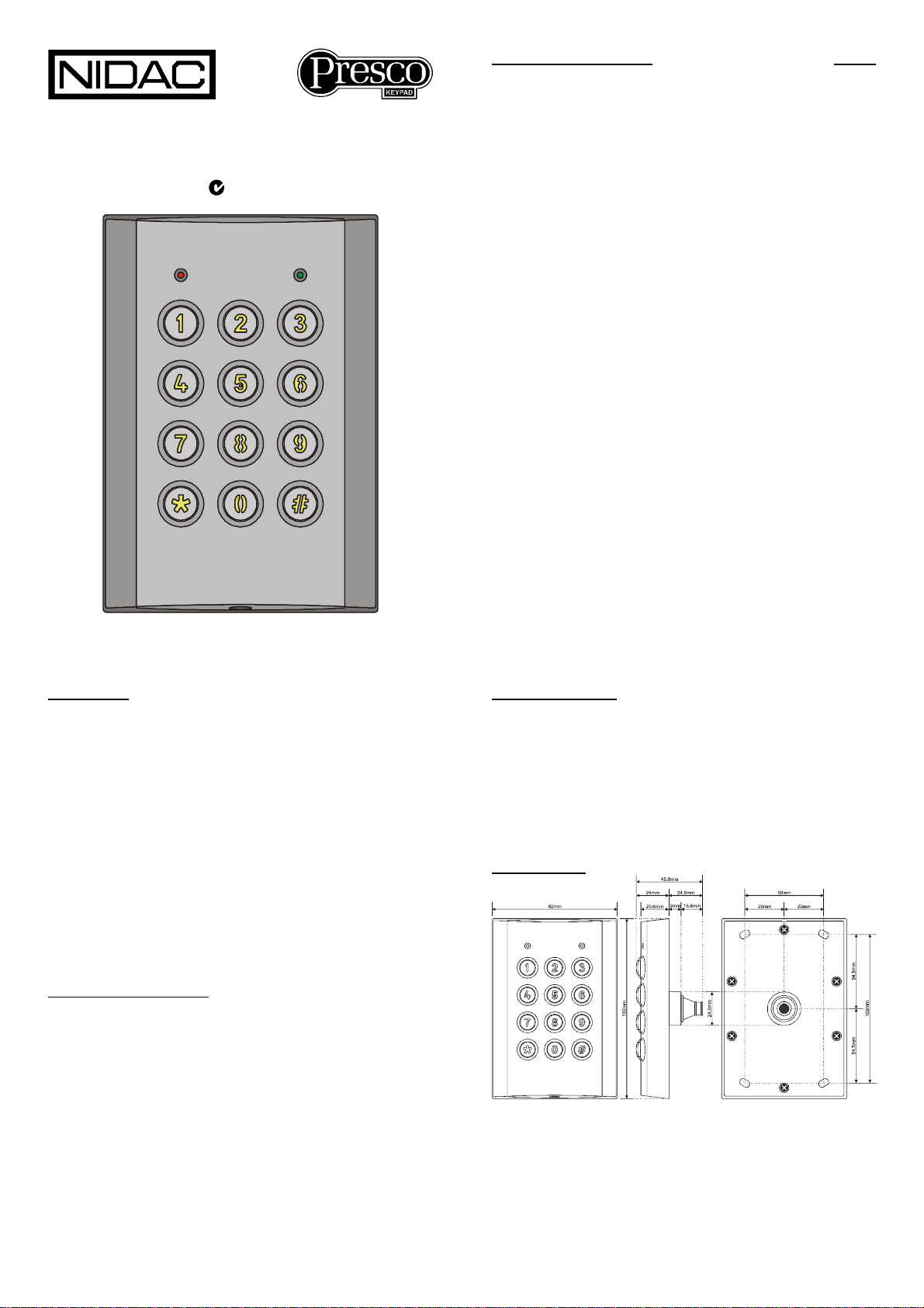
DIMENSIONS

3
WIRES
Thereare 12 wires fortheVR43 keypads, notallwill be needed
foreachinstallation, The unusedwiresshouldalwaysbe
terminatedandleftunconnected.
Black 0V (Ground).
Red +5V to +12V D.C.
White DTA (Presco™data line).
DarkGreen D0 (Weigand Data 0).
Yellow D1 (Weigand Data 1).
Violet +12V D.C. Backlighting.
Blue Green LED controlwire,+3Vto +12V active.
Orange Red LED control wire,+3V to +12V active.
Brown Buzzer controlwire,0V active.
Light Green Green LED controlwire,0V active.
Pink Presco™/Weigand mode selectwire,0V active.
Grey Chassis Earth connection.
NOTE: The Blue,Orange,Brown,Light Green andPinkwires
canbe programmedto controldifferent functions.Refertothe
Optionssection onpage 8.
IMPORTANT: Whenusing theVR43 in anarea subjectto static
discharges thechassisofthe VR43 shouldbe connectedto
EARTHviathegrey wire. It is highlyrecommended that this
always be doneno matter what the environment.
4
INSTALLATION
1.Usingthesupplied templatemarkoutthelocationofthe
mountingscrewsand thecableexit.Drilloutall points as
necessary.
2.Usingthe supplied keyremove thehexallenscrewat the
bottomof theVR43 thatsecurethe fascia to thechassis.
3.Swingthe fasciaupfrom thebottomanditwillunhook atthe
top allowing access tothemountingscrew holes.
4.Attachthesupplied cablebyplugging in theconnector (you
mayneed to useascrewdriver topushtheconnector
aroundtheedges to ensureitisinfirmly). Note that itis
designed to beinsertedinonewayonly,howeveruseof
excessive force couldallowitto be inserted wronglyso
checktheguide locators match beforeinserting.
5.Slide therubberbootdownthecableandpressthefirst
flange into thehole andleavingthesecond flange onthe
outside of the keypad. Make surethat it sitsneatlyinall
places to ensure a correct seal.
6.Mountthekeypad andreversesteps2&3to reattachthe
fasciato thekeypad chassis.
5
USING THEVR43KEYPADSWITHPRESCO™
TheVR43 can be used to performall thefunctions ofa standard
PrescoPRE keypad. Theonlydifference inoperationis the use
ofthe #keyinstead of the Ekey.
The #keyis adualpurpose key.Whenit is pressedas the first
keyinacode sequenceit generates a#, whenpressed asa
subsequent keyitthen becomes the Ekey.
Shoulditbe necessaryto generate a#in themiddleof acode
sequence thenyoumustpressandholddownthe *key,press
the #key thenrelease both keys.
Touse thekeypadinPresco™mode, press thecodethenthe
#key.The keypad canbeset up to automaticallysendthe
code afteragivennumberofkeypresses bysetting memory
007 (refer to the OPTIONS section onpage8).
ExampleCode Sequences
PRE sequence VR43equivalent
1. *000 1E*000 1#
2. 1234 E1234 #
3. #000 E#000 #
Remembertopress #afterthecode tosend it unlessmemory
007 has beensetto auto send after a given number of keys.
6
VR43 TO PAC1 /PAC2 WIRING DIAGRAM
VR43 TO KC6, KC6 & PDAWIRING DIAGRAM

7
USING THEVR43KEYPADSWITHWEIGAND
TheVR43canbe used withany standard weigandand most
nonstandard weigand controllers.The site (facility)codecanbe
set from the keypad itself (referto theWeigandOptionssections
onpage 9)andthe weiganddata isfully configurablewith up to
64 bits of data. TheVR43 keypads also support controllers that
require burstmode formatweigand.
ThePinkwire needsto be connected to 0V (theBlackwire)to
set Weigandoutput mode (unlesstheunithasbeen
programmed to force it into Weigandmode viamemory005
(refer to the WeigandOptions sections onpage 9)
Touse thekeypad inweigand(nonburst) mode, pressthecode
thenthe #key.Thekeypadcan be setupto automatically
sendthe codeafteragiven numberof keypressesby setting
memory007 (refer tothe OPTIONS section onpage 8).
VR43 TOWEIGAND WIRING DIAGRAM
Remembertopress #afterthecode tosend it unlessmemory
007 has beensetto auto send after a given number of keys.
8
OPTIONS
Thereareseveraloptions that canbe settoalterthewayin
whichtheVR43 keypad behaves. Theseoptionsfallinto the 3
categoriesof General,WeigandandPresco™, allofthese are
explained below.
Theoptionscanbe set fromeitherthekeypad itselfor through
theuse of aPIM(series2orlater)and thePIM-VR software
availablefromourwebsite http://www.nidac.com inthe
downloads sectionundersoftware. Refertothehelpfile
supplied withthesoftwarefordetailsonhowtouse the PIMto
set the VR43 keypadoptions.
GeneralOptions
These optionsset thefunctionalityoftheblue, orange, brown,
light greenandpinkcontrolwiresaswellas other options that
are independentof whether thekeypad isin Weigandor
Presco™ mode.
Memory
Number
Function Default
Value
000 Bluewirecontrol (1) 1
001 Orange wirecontrol (1) 2
002 Brownwirecontrol (1) 4
003 LightGreenwirecontrol (1) 1
004 Pinkwirecontrol (1)(2) 2
005 ForcePrescoorWeigandmode (3) 255
006 Keypresstimeout 10
007 Autosend keycount (4) 0
008 Keypressesproduceabeep&flashredLED(5) 255
(1)-Wirecontrolvalues [Memories000 to004]
0=Nothingcontrolled. 4=Buzzer.
1=GreenLED. 5=Green LED+Buzzer.
2=RedLED. 6=Red LED+Buzzer.
3=GreenLED+Red LED. 7=Green LED+Red LED+Buzzer.
(2)-Pinkwirecontrol [Memory004]
ThePinkwireisalways used toselectPrescoorWeigand modeunless
memory005 issettoeither101or202(seememory005,note3).
9
(3)-ForcePrescoorWeigandmode [Memory005]
101 =Always inPrescomode.
202 =Always inWeigandmode.
Allothervalues=Modeselectedbypinkwire.
(4)-Autosendkey count [Memory007]
WhenthismemoryissettoanonzerovaluetheVR43 will automatically
send thedataafter xkeyshavebeenpressed,where x=valuesetfor
thismemory.
Note:InPrescomode theautosendisdisabledifthefirst keypressedis
a *or #.
(5)-Keypress audio&visualconfirmation [Memory008]
101 =Keypressescausethe redLEDtoflashbutnobeepissounded.
151 =KeypressescauseabeeptosoundbuttheredLEDdoesn’tflash.
202 =Keypressesprovidenovisualoraudioconfirmation.TheredLED
doesn’tflashandno beepissounded.
Allothervalues=Keypressescausesabeeptosoundandthe red LED
toflash.
Weigand Options
These optionssetthe format of theWeiganddata sentbythe
keypadwhenWeigandmode is selected.The keypad cansend
upto 64 bits of dataincluding a site code up to32bits.
Memory
Number
Function Default
Value
020 SiteCodebyte3 0
021 SiteCodebyte2 0
022 SiteCodebyte1 0
023 SiteCodebyte0(usedforstandard8bitsitecode) 1
024 Numberof bitsinSiteCode(0to32) 8
025 Numberof bitsinUserCode(8to64) 16
026 Numberof bitsforstartparitycalculation 12
027 Numberof bitsforendparitycalculation 12
028 Paritypolarity (6) 2
029 Errorhandling (7) 255
032 Weigandburst mode (8) 255
033 CustomWeigandtotalnumberofbits (9) 255
034 SendLSBfirst (10) 255
10
Memory
Number
Function Default
Value
035 SiteCodestartbit number 255
036 UserCodestart bitnumber 255
040 DefaultCustomWeigandPatternbyte7 (11) 255
041 DefaultCustomWeigandPatternbyte6 (11) 255
042 DefaultCustomWeigandPatternbyte5 (11) 255
043 DefaultCustomWeigandPatternbyte4 (11) 255
044 DefaultCustomWeigandPatternbyte3 (11) 255
045 DefaultCustomWeigandPatternbyte2 (11) 255
046 DefaultCustomWeigandPatternbyte1 (11) 255
047 DefaultCustomWeigandPatternbyte0 (11) 255
(6)-ParityPolarity [Memory028]
0=Start parityisEven,EndparityisEven.
1=Start parityisOdd,EndparityisEven.
2=Start parityisEven,EndparityisOdd(default value).
3=Start parityisOdd,EndparityisOdd.
(7)-ErrorHandling [Memory029]
Thismemoryspecifieswhatinformation issentviatheWeigand
interfacewhen acodeisentered thatistoolarge toberepresented by
thecurrentWeigand format.
Eg.Standard26 bitWeigand hasa16 bitusercodewhichallowsa
maximumcodenumberof65535.Thismemorydetermineswhat
happenswhen anumbergreaterthen65535 isentered.
101 =Acodeof 0issent.
202 =Noinformationissent, thekeypadignorestheinput.
Allothervalues=The maximumallowablecode numberforthecurrent
formatissent (for26bit Weigandthisis65535).
(8)-Weigand burstmode [Memory032]
101 =4bit burstmode, *& #keysenabled.
121 =4bit burstmode, *& #keysdisabled.
202 =8bit burstmode, *& #keysenabled.
212 =8bit burstmode, *& #keysdisabled.
Allothervalues=Standardnon burstmodeWeigand.
(9)-CustomWeigand totalnumberofbits [Memory033]
Whenthismemoryissettoavaluefrom8to64 it overridesthestandard
Weigandformatof start parity followed by sitecode then usercode then

11
end parity and replacesitwithafullycustomisableformatwithatotal
numberofbits(includinganyparitybits)asspecifiedinthismemory.
Setting thismemorytoavalueoflessthan8orgreaterthan64will
causetoPIMtousethe standardWeigandformat.
Note thatusingthisoptionrequiresahighunderstandingofWeigand
data. Nidacwill onlyofferlimitedsupportforthisfeature.
(10)-SendLSBfirst [Memory034]
101 =LSBofdataissent firstforbothsiteandusercode.
Allothervalues=MSB ofsiteandusercodedatasent first.
(11)-DefaultPatternbytes [Memories040 to047]
WhenthecustomWeigandformatisusedbysettingmemory033then
thedatainthesememoriesisusedtodefinethe valueforthosebitsnot
inusebythesitecode,usercodeandparitybits.Thedataused starts
fromBit0(LSB)inDefaultPatternbyte0(memory047),e.g.if the total
numberofbitsisset to24 thenDefaultPatternbytes2, 1&0areused.
Presco™ Options
These optionssethowthekeypad operates wheninPresco™
mode.Itishighlyunlikelythatthese optionswill ever need tobe
changed.
Memory
Number
Function Default
Value
060 Internal/ExternalmodePrescokeypad (12) 255
061 ProcessreceivedDTAcharsmode (13) 255
(12)-Internal/ExternalmodePrescokeypad [Memory060]
101 =Internalmodekeypad.
Allothervalues=Externalmodekeypad.
Note: Whensettointernalmodethe twobuttonEmergency(*#)and
OneWayArm (##)featuresareenabledwhenusedwithaKC2or
KC6.Thissetting hasnoeffectwhentheunitisbeingusedwithany
otherPrescodecoder(e.g. PAC1orPAC2).
(13)-ProcessreceivedDTAcharsmode [Memory061]
101 =IgnoreallreceivedDTAchars(keypadwillnotgivebeeps,warble,
etc.afterfinal #ispressed).
202 =Makenoisesforall receivedvalidDTAcharsreceived.The
keypad willgeneratebeeps,warble,etc.forall charsreceived at
anytimeandafterfinal # keyispressed.
12
Allothervalues=Keypad will onlymakebeeps,warble,etc.forDTA
charsreceivedafterpressingthefinal # key.
Note: Thismemoryonlyhasan effectwhenthe keypad isinPresco
mode (eitherthrough the PinkwireorMemory005=101),inWeigand
modeall received charsonthe DTAlineareignored.
Setting the optionsviathe VR43keypad
Tosetanyoftheaboveoptionsthekeypadfirst needs tobe
placed into program mode, thisisdonebythe following method:
1.Remove power fromtheVR43.
2.Holddown the 3, 6& 9keys.
3.Reapply power whilst continuingto hold downthekeys.
4.Oncethered &green LEDs starttoflashalternativelyto
indicateyou arein programmode releasethe keys.
5.The keypad will remaininprogram for5mins fromthelast
attemptedprogramming sequence.
Programming amemory
*<3 digitmemorynumber><1 to 3digit memory value> #.
Resetallmemoriesto factorydefaults
*987654# whilstinprogram mode.
ExitProgram Mode
*999# or wait5 minutes afterlastprogramming attempt.
13
WARRANTY
Themanufacturerwillreplaceorrepairthisproduct if provento
be faulty(excludingaccidentalormaliciousdamage)under the
36 monthwarrantyoffered fromthe date ofpurchase.
AsNIDACSecurityPty.Ltd. orit’sagentsdo notperformthe
finalinstallation,inspection ortrainingintheuse ofthisproduct,
theycannot be heldliableforinjury, lossordamagedirectlyor
consequentially arisingfromtheuseormisuse ofthis product.
Thesoftware designoftheNIDAC Presco™ isprotected
internationally. Designimprovementand specificationchanges
are subjecttochange withoutnotice. All designsare copyright
protected.
OTHERPRODUCTS
VR62 Slimline6x2format vandal&weatherresistant
Presco™keypad encoder for allPresco™decoders.
PRE StandardPresco™keypad encoderforallPresco™
decoders,available in charcoalor ivory.
PAC1 SingleDoorAccess Controller, 5A. 30V ElectricLatch
ControlSPSTrelay,400 timedortoggled usercodes,
12-24V D.C.or 16-24V A.C. operation. Door OpenToo
Long, Door Forced and EGRESSfunctions builtin.
PAC2 2 DoorAccessController,samefeatures asPAC1 but
cancontroltwodoors independently.
Sprite Presco™proximity cardreaderforPAC1, PAC2or
Weigand inputcontroller.
PIM Presco™InterfaceModule converts fromPresco™,
DallasiButton™, Clock&Data (MagneticCard)or
Weigand to Presco™,RS232 or Weigand.
CT1 Userconfigurable general purposetimermodule.
VR43Instructions.doc 13/01/2009Revision 1.1
100%
Designed andManufacturedby:
NIDAC SECURITYPTY. LTD.
2CROMWELLSTREET
BURWOOD,VICTORIA Tel:(03) 9808 6244
AUSTRALIA 3125 Fax:(03) 9808 9335
Other Nidac Keypad manuals


