Ksenia ergo-X KSI2100031.302 Use and care manual

code R30045.110en www.kseniasecurity.com
ed.06/2022
ergo-X
BUS outdoor keypad
User and installer
manual
INTRODUCTION
ergo-X keypad is an access control user interface connected to and powered by the BUS of lares 4.0 control
panel. The keypad case is compliant with IP65 protection degree so that it can be installed outdoors and
does not require additional protection.
ergo-X keypad allows the user to run any type of scenario in the following ways: place your mini-Tag near
RFID reader on the keypad and then press the key that activates the desired scenario; enter your code and
then press a programmed key (with PIN); long press the programmed key (without PIN).
Scenarios and colors of RGB led associated can be remotely customizable from Installer App.
ergo-X keypad has two I/O terminals that can be programmed as inputs with EOL resistors or as Open
Collector outputs up to 500mA each.
TECHNICAL CHARACTERISTICS
• Power supply 13.8 Vdc
• Consumption max 200mA
• Mechanical membrane keypad
•RFIDTagreader
• Automatic backlight keys
• RGB led with customisable colors for system status signalling
• Feedback sound on operations
• Tamper switch anti-removal
• 2 terminals I/O (OC 500 mA max)
• Protection degree IP65 (compliant with EN 60529:1991 /A1:2000 /A2:2013)
• Resistance impact protection IK09 (compliant with EN 62262:2002)
• Temperature range: from -20°C to +55°C
• Mount adapter plate + 2m unshielded cable (8x0.22)
• Dimensions 72 x 113 x 20.5 mm (LxHxW)
• Color: black, light grey
KSI2100031.302 - ergo-X black
KSI2100031.303 - ergo-X grey

code R30045.110en www.kseniasecurity.com
ed.06/2022
PRODUCT DESCRIPTION
ergo-X keypad
Mount adapter plate
RGB LED
Numerical keys [0...9] and key [X]
mini-Tag
RFID Area
Support hooks
Holes for wall mounting with flat head screws (holes
distance 40mm)
Hole for locking screw

code R30045.110en www.kseniasecurity.com
ed.06/2022
RGB LED multicolor
The led, if personalized, takes the same color as the arming status of the system. The colors associated with
the preconfigured scenarios are:
• red = total armed
• blue = partial armed
• green = disarmed
The led lighting timer can be configured (P.V.: 0 = always ON, timer from 1 to 240 seconds).
Important note
When the “Display zones status” option of ergo-X is enabled:
1. the yellow flashing led indicates that a memory alarm is present in case the system is disarmed or
there is an alarm in progress/restored in case the system is armed. The flashing yellow alternates with
the with the color of the arming state. For example:
- green/yellow = system disarmed/alarm memory;
- red/yellow = system armed/alarm in progress or restored.
2. the led OFF indicates that the system cannot be armed due to some zones in alarm. Led can turn ON
when you exclude those zones.
RFID Area
The keypad has an antenna on board with which recognizes the user's key/mini-Tag and that allows the
installer to enroll the key/mini-Tag.
Keys 0...9
The numeric keys (from 0 to 9) are used to enter the PIN code and to run the scenario associated with the
configuration. It is possible to configure each key "With PIN", so that the user must enter the code before
pressing the key that runs the scenario, or "Without PIN", in this case the user does not have to enter the
code but simply hold down for 3 seconds the key that runs the scenario.
The keys light up automatically the moment your hand approach to enter the code and at the end the light
will turn off. Just in case a sabotage occurs, the keys remain lit.
Key X
While entering the PIN code, it is possible to cancel the wrong digits by pressing <X> key.
Buzzer
Feedback sound on operations can be enable/disabled.

code R30045.110en www.kseniasecurity.com
ed.06/2022
INSTALLATION
Contents of the package:
•1ergo-Xkeypad
• 2m unshielded cable (8x0.22)
• 1 mounting adapter plate
• 1 adapter plate locking screw
• 2 wall plugs and screws
• 1 adhesive mounting template size 1:1
BUS and Terminals I/O cabling
The example below shows how to connect ergo-X to lares 4.0 BUS using the 8x0.22mm unshielded cable:

code R30045.110en www.kseniasecurity.com
ed.06/2022
Details of unshielded cable (8x0.22):
The example below shows how to connect M1 and M2 terminals using the 8x0.22mm unshielded cable.
Characteristics of the two terminals are:
• Input (Programmable zones) (connection to the ground terminal)
or
• Output Open Collector at 500mA each (connection to the positive terminal +P).
Connect M1 terminal programmed as an input/zone, as the example below:
Connect M2 terminal programmed as an output, as the example below:
= +
= A
= B
= -
= -
= M2
= M1
= +P

code R30045.110en www.kseniasecurity.com
ed.06/2022
Mount adapter plate installation
1. Fix the mount adapter plate directly to the wall using two Ø 5mm expansion anchors and Ø 3.5mm
flat head screws. To drill the holes, use the supplied adhesive mounting template, size 1:1, and attach
it to the wall; place the bracket on the dotted box and drill two holes in correspondence with the X
indicated by the arrows (see image below):
2. bring the back of the keypad close to the bracket making it match up with housing section;
3. slid the keypad downwards until the bottom matches the bottom of the bracket;
4. lock the bottom of the keypad using the screw provided.
KEYPAD - BACK VIEW
Support holes
Housing section for bracket plate
Tamper switch anti-removal
Cable exit hole
Keypad locking screw

code R30045.110en www.kseniasecurity.com
ed.06/2022
CONFIGURATION
The software configuration supplied by Ksenia is required.
Keypad programming instructions
Open <BUS peripherals -> User interfaces -> ergo-X> menu, if correctly installed, ergo-X will show its serial
number so it can be added in the system configuration by clicking on icon and then wait for the
green icon as positive feedback. To finish, fill in the optional fields and the numeric keys to run the
scenarios, save and apply configuration.
The contextual help describes whatever here is omitted. For all the details, please consult the “lares 4.0
programming manual”.
Key/mini-Tag programming instructions
Start recognition procedure of user’s key/mini-Tag by clicking “Enroll tags” icon from <System -> Users>
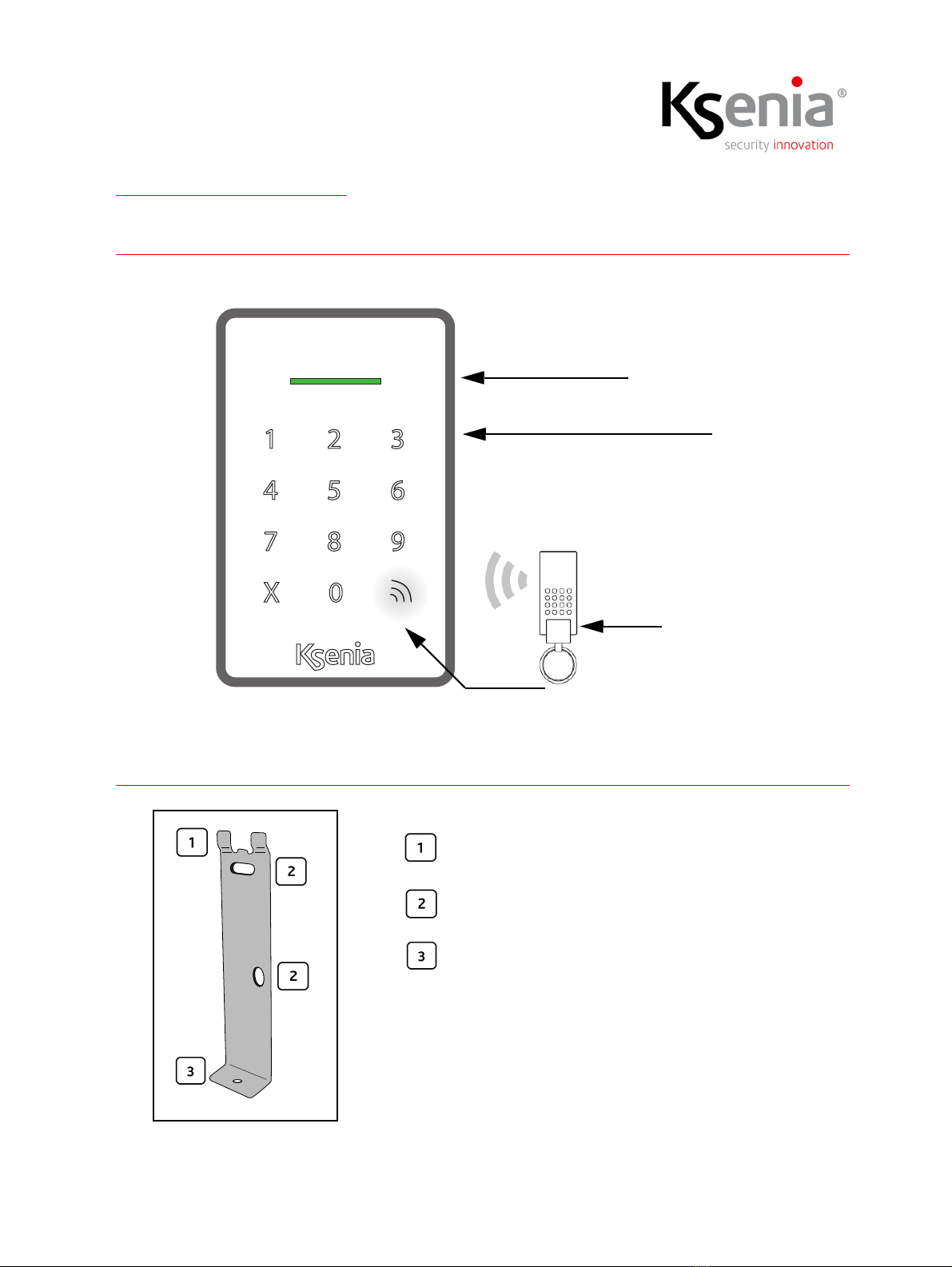
menu, then select “ergo-X” device and click on <START> button. Put the tag close to the ergo-X RFID area
and wait for a few seconds until you’ll see the number code displayed; at this point, select a name from the
Users list and click on STOP button to end the procedure. Repeat the procedure for each user with a key/
mini-Tag.
Led RGB programming instructions
In addition to the standard arming color (red, green, blue) of the RGB LED, to display the arming status of the
system, it is possible to recognize when one or more specific partitions associated with the keypad are
armed, thanks to a further customization of fuchsia, white and cyan led colors.
Open <BUS peripherals -> User interfaces -> ergo-X> menu, there are three fields, one for each led color
(e.g.: “Partitions associated with Fuchsia color”), program each field by choosing some partitions among
those to which the keypad belongs.
In our example the keypad led will turn fuchsia when the armed partitions are exactly the ones customized
in this field.
If they do not match, the configuration of the "Partition associated with White color" field will be checked
and then the one of "Partition associated with Cyan color".
Again, if there is no match, then the led takes one of the standard colors (red, green, blue) according to the
arming status.
Scenarios/events programming instructions
To enable the user to arm the system by pressing <1> on ergo-X, for example, the installer must program:
the "Keypad" event with “Key 1” subtype and associated with the "Arming Mode" scenario.
From <System -> Scenarios> menu you can program any scenario and from <System -> Events> menu the
identities (keypad, users, zones, outputs, etc.) that generate the event to run the scenario.

code R30045.110en www.kseniasecurity.com
ed.06/2022
The contextual help for the page describes whatever here is omitted. For all the details, please consult the
“lares 4.0 programming manual”.
Terminals I/O programming instruction
Two terminals (M1 and M2) are integrated inside the ergo-X, they can be programmed as inputs (from
<System -> Zones> menu) or as outputs (from <System -> Outputs).
The contextual help for the page describes whatever here is omitted. For all the details, please consult the
“lares 4.0 programming manual”.
Diagnostic
A useful page for technical operators is available to monitor the status of all the BUS peripherals connected
to BUS1 and BUS2 of lares 4.0, from <Installer -> Diagnostic> menu.

code R30045.110en www.kseniasecurity.com
ed.06/2022
USER GUIDE
The user can perform the following functions, the success of them depends on the system configuration.
Note:
a) when you press a key you can hear a beep feedback, if the buzzer is enabled, otherwise you can see a
blinking of keys. In case no feedback is received, repeat the operation and increase the pressure on the key;
b) you have 5 seconds between two operations (entering PIN and pressure of key). If the timer expires, just
repeat the operation.
Running a scenario from keypad
With PIN: [PIN + 0...9]
• Enter your code and then press the key to execute the desired scenario. The RGB led will take the same
color as the programmed scenario, if it changes the arming status of the system. According to the
configuration, the RGB led can be configured always ON or turn off when the timer expires.
Without PIN: [0...9]
• Hold down the programmed key and wait for 3 seconds to execute the scenario desired. The RGB led
will take the same color as the programmed scenario, if it changes the arming status of the system.
According to the configuration, the RGB led can be configured always ON or turn off when the timer
expires.
Incorrect PIN code
• For recovering eventual errors while entering the PIN code, it is possible to cancel the wrong digits by
pressing <X> key.
• Incorrect PIN code blocks the keypad for 5 minutes after the third wrong attempt.
Running a scenario from mini-Tag
Place your mini-Tag near RFID reader on the keypad ( ) and then press the key that activates the desired
scenario. The RGB led will take the same color as the programmed scenario, if it changes the arming status
of the system. According to the configuration, the RGB led can be configured always ON or turn off when
the timer expires.
Cleaning the keypad
Use a soft and moistened cloth with water to clean externally the keypad.

code R30045.110en www.kseniasecurity.com
ed.06/2022
QUANTITY DATA
Technical specification, appearance, functional and other product characteristics may change without notice.
COMPLIANCE
Europe - Rohs, CE
EN 60529:1991 /A1:2000 /A2:2013 (IP65)
EN 62262:2002 (IK09)
Warning! Do not use an ordinary dustbin to dispose of this equipment.
Used electrical and electronic equipment must be treated separately, in accordance with the relative legislation which
requires the proper treatment, recovery and recycling of used electrical and electronic equipment.
Following the implementation of directives in member states, private households within the EU may return their used
electrical and electronic equipment to designated collection facilities free of charge*. Local retailers may also accept
used products free of charge if a similar product is purchased from them.
If used electrical or electronic equipment has batteries or accumulators, these must be disposed of separately according
to local provisions.
Correct disposal of this product guarantees it undergoes the necessary treatment, recovery and recycling. This prevents
any potential negative effects on both the environment and public health which may arise through the inappropriate
handling of waste.
*Please contact your local authority for further details.
Installation of these systems must be carried out strictly in accordance with the instructions described in this manual, and
in compliance with the local laws and bylaws in force. These products have been designed and made with the highest
standards of quality and performance adopted by Ksenia Security. Is recommended that the installed system should be
completely tested at least once a month. Test procedures depends on the system configuration. Ask to the installer for
the procedures to be followed.
Ksenia Security spa shall not be responsible for damage arising from improper installation or maintenance by
unauthorized personnel.
The content of this guide can change without prior notice from KSENIA SECURITY.
lares 4.0 models wls 96 16 40 40 wls 140 wls 644 wls
Maximum number of BUS user
interfaces
3 6 24 24 40 64
This manual suits for next models
1
Table of contents
Other Ksenia Keypad manuals

Ksenia
Ksenia ergo-T User manual

Ksenia
Ksenia ergo-T User manual

Ksenia
Ksenia ergo A KSI2100030.301 WHITE User manual

Ksenia
Ksenia ergo M Assembly instructions

Ksenia
Ksenia ergo M User manual

Ksenia
Ksenia ergo M User manual

Ksenia
Ksenia ergo wls KSI2100022.301 User manual

Ksenia
Ksenia ergo wls User manual

Ksenia
Ksenia ergo Operating instructions

Ksenia
Ksenia KSI2100000.300 Operating instructions