Nido Robotics Sibiu Nano User manual

Sibiu Nano - Assembly Manual (English)
With this guide you will learn how to assemble your Sibiu Nano Maker Kit.
Escrito por: Nido Robotics
Sibiu Nano - Assembly Manual (English) Borrador: 2019-01-22ID de guía: 20 -
Este documento fue generado el 2019-10-04 02:18:54 AM (MST).
© 2019 nido.dozuki.com/ Página 1 de 31

INTRODUCCIÓN
Do you have a Sibiu Nano Kit? Now you can start the assembly process. It is a simple procedure
following these steps. You wont have to solder or pot.
Sibiu Nano - Assembly Manual (English) Borrador: 2019-01-22ID de guía: 20 -
Este documento fue generado el 2019-10-04 02:18:54 AM (MST).
© 2019 nido.dozuki.com/ Página 2 de 31

Paso 1 — Structure components
2 x Side panels
2 x Upper clamps 2 x Middle clamps 2 x Lower clamps
4 x Motor brackets 2 x Vertical motor brackets.
2 x Front mounts 2 x Rear mounts
1 x Rear shaft
1 x Bottom panel
1 x Float
Sibiu Nano - Assembly Manual (English) Borrador: 2019-01-22ID de guía: 20 -
Este documento fue generado el 2019-10-04 02:18:54 AM (MST).
© 2019 nido.dozuki.com/ Página 3 de 31

Paso 2 — Bottom panel sub-assembly
1 x Bottom panel
2 x Lower clamps
4 x R6 7/8 Screws (Bag 1)
Starting the assembly. The first step is the bottom sub-assembly. The lower clamps are installed
on the bottom panel slots with its correspondent screws.
Sibiu Nano - Assembly Manual (English) Borrador: 2019-01-22ID de guía: 20 -
Este documento fue generado el 2019-10-04 02:18:54 AM (MST).
© 2019 nido.dozuki.com/ Página 4 de 31

Paso 3 — Motors sub-assembly
2 x Front mounts
2 x Rear mounts
4 x Motor brackets
8x R6 7/8 Screws (Bag 1)
In this step, the motor brackets are installed into the mounts' slots.
Install 2 screws per bracket.
Every motor bracket must be installed with the rounded edge facing outward as shown on the
picture 2
The position of each motor sub-assembly on the picture 2.
Sibiu Nano - Assembly Manual (English) Borrador: 2019-01-22ID de guía: 20 -
Este documento fue generado el 2019-10-04 02:18:54 AM (MST).
© 2019 nido.dozuki.com/ Página 5 de 31

Paso 4 — Top sub-assembly
2 x Upper clamps
2 x Vertical motor brackets
8 x R6 7/8 Screws (Bag 1)
The vertical motors brackets are assembled to the upper clamps arranging the top sub-assembly.
The lateral slot on the brackets must be facing inward the sub-assembly just like shown in the
pictures.
Sibiu Nano - Assembly Manual (English) Borrador: 2019-01-22ID de guía: 20 -
Este documento fue generado el 2019-10-04 02:18:54 AM (MST).
© 2019 nido.dozuki.com/ Página 6 de 31

Paso 5 — Assembling the side panels into the bottom sub-assembly
2 x Side panels
1 x Bottom sub-assembly
4 x R6 7/8 Screws (Bag 1)
The bottom sub-assembly is installed into the side panels' slots.
The bottom sub-assembly is symmetric, so the orientation does not matter.
For the next steps, keep in mind the orientation shown in the picture 1.
Red arrow: Front
Blue arrow: Rear
Sibiu Nano - Assembly Manual (English) Borrador: 2019-01-22ID de guía: 20 -
Este documento fue generado el 2019-10-04 02:18:54 AM (MST).
© 2019 nido.dozuki.com/ Página 7 de 31

Paso 6 — Motors sub-assembly to side panels
2 x Front motors sub-assembly
2 x Rear motors sub-assembly
8 x R6 7/8 Screws (Bag 1)
Remember the position of the motors sub-assemblies (picture 1) when installing them into the side
panels.
The mounts are fitted into the side panels' slots.
After this step, the frame should look like picture 3
Sibiu Nano - Assembly Manual (English) Borrador: 2019-01-22ID de guía: 20 -
Este documento fue generado el 2019-10-04 02:18:54 AM (MST).
© 2019 nido.dozuki.com/ Página 8 de 31

Paso 7 — Preparing the battery flanges
2 x flanges with o-rings set and silicon grease tube
1 x front battery end cap (no holes)
1 x rear battery end cap (2 holes)
12 x M3x14 screws (Bag 3)
Before installing the battery enclosure, the flanges must be assembled with their end caps and o-
rings. The front battery flange is shown at picture 3.
First of all, apply a little amount of silicon grease on the o-rings.
Use the screws for installing the end caps.
It is important to avoid the presence of any particles or dust on the o-rings.
Sibiu Nano - Assembly Manual (English) Borrador: 2019-01-22ID de guía: 20 -
Este documento fue generado el 2019-10-04 02:18:54 AM (MST).
© 2019 nido.dozuki.com/ Página 9 de 31

Paso 8 — Battery enclosure installation
1 x Acrylic tube (200 mm)
1 x Bottom + Motors sub-assembly
The bottom clamps must have the non-slip tape, as shown in the picture.
Put the battery enclosure on the bottom clamps. The front end cap must be resting on the front
mounts as shown in the picture 2.
Sibiu Nano - Assembly Manual (English) Borrador: 2019-01-22ID de guía: 20 -
Este documento fue generado el 2019-10-04 02:18:54 AM (MST).
© 2019 nido.dozuki.com/ Página 10 de 31

Paso 9 — Mid clamps assembly
2 x Mid clamps
4 x M3x25 Screws (Bag 4)
8 x M3x18 Screws (Bag 5)
12 x M3 nuts
The slots remarked at the picture 1 must be facing upwards.
Introduce the M3x25 screws and joint the motor mounts with the mid clamps (picture 3).
Sibiu Nano - Assembly Manual (English) Borrador: 2019-01-22ID de guía: 20 -
Este documento fue generado el 2019-10-04 02:18:54 AM (MST).
© 2019 nido.dozuki.com/ Página 11 de 31

Paso 10 — Mid clamps assembly
Now, introduce the M3x18 screws to join the mid clamps and the lower clamps.
Using the upper hole of the mid clamp it will be easier (picture 1).
A small deviation of the clamps' holes may block the nut. If this is your case, you can introduce the
screw from the bottom.
Paso 11 — Assembling the float to the top sub-assembly
2 x R6 - 7/8 Screws (Bag 1)
4 x R8 - 1" Screws (Bag 9)
Put the top sub-assembly on the frame (without screws).
Sibiu Nano - Assembly Manual (English) Borrador: 2019-01-22ID de guía: 20 -
Este documento fue generado el 2019-10-04 02:18:54 AM (MST).
© 2019 nido.dozuki.com/ Página 12 de 31
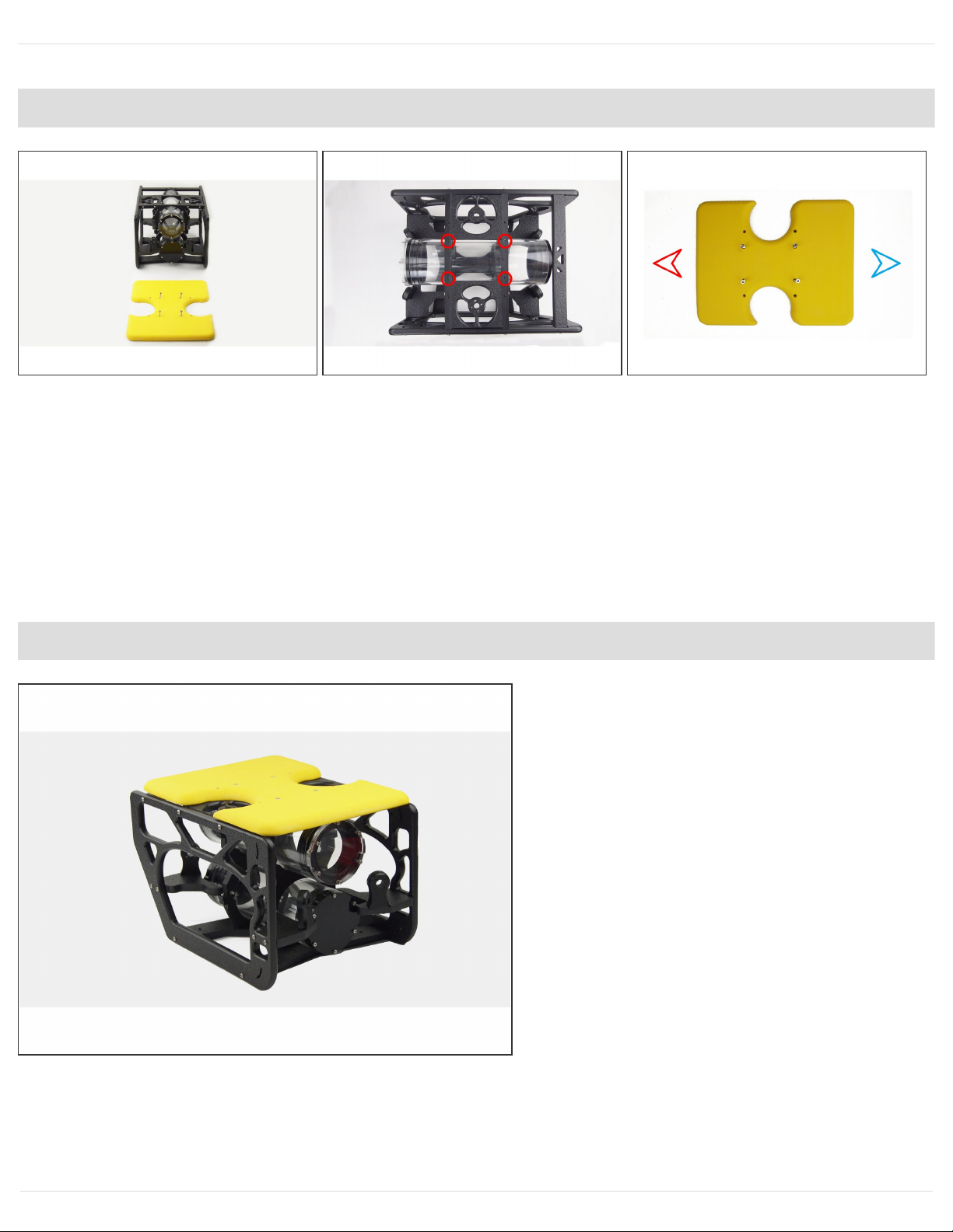
Paso 12 — Assembling the float to the top sub-assembly
Put the float on the top of the frame. Use the R8 - 1" screws on the hloles marked in the picture 2.
The orientation of the float is the following (picture 3)
Red arow: front
Blue arrow: Rear
Paso 13 — Frame finished
The frame is finished, lets continue
with the electronics and thrusters
assembly.
Sibiu Nano - Assembly Manual (English) Borrador: 2019-01-22ID de guía: 20 -
Este documento fue generado el 2019-10-04 02:18:54 AM (MST).
© 2019 nido.dozuki.com/ Página 13 de 31
Paso 14 — Electronics Assembly. For PCB's model 0.4 (white PCB's) go to next step.
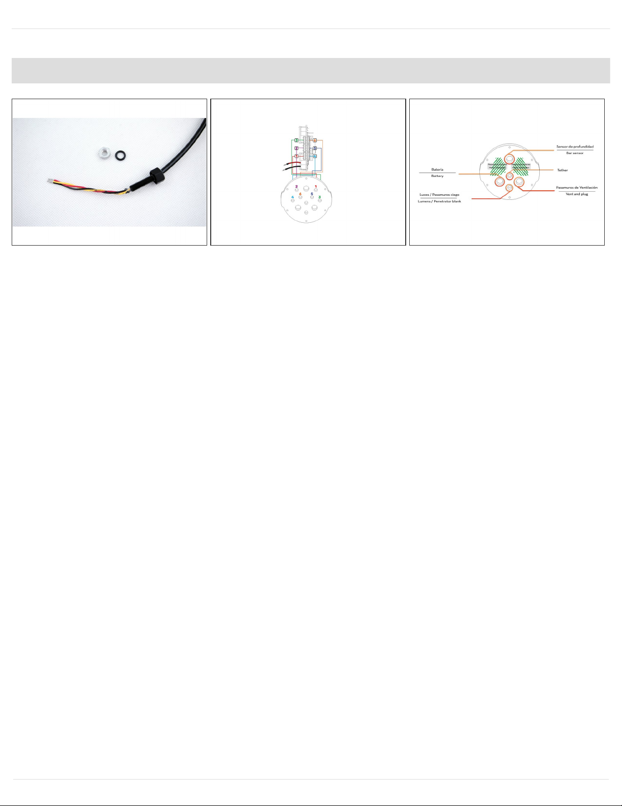
First of all, lets install every penetrator to the rear electronics end cap.
Put a little amount of silicon grease on every penetrators' o-ring.
At the picture 2, a diagram o the thrusters connection is shown. Check carefully the numeration of
each thruster which defines the position in the frame, and into the end cap.
At the picture 3 you can see the rest of the penetrators layout.
When installing the lights penetrator, the black connector must be removed from the yellow cable.
Pull up the tab carefully and pull the cable out. After introducing the penetrator, put it back again.
In order to introduce the battery cable, pass one wire first and then the other. They may be difficult
to introduce into the nut. If necessary, remove the heat-shrink and put it back again after installing
the penetrator.
Motor configuration varies depending on the PCB model of your Nano. If your Nano has the PCB
model 0.4, please follow the next step for the right thruster configuration.
Sibiu Nano - Assembly Manual (English) Borrador: 2019-01-22ID de guía: 20 -
Este documento fue generado el 2019-10-04 02:18:54 AM (MST).
© 2019 nido.dozuki.com/ Página 14 de 31

Paso 15 — Thruster assembly for PCB's 0.4 (white PCB's)
Please follow this scheme for a right
motor configuration in PCB's model
0.4 (white PCB's).
Paso 16 — Penetrator installation
The installation of each penetrator must be done as follows:
Put the o-ring into the slot of the penetrator's head.
Install the penetrator in the end cap, and the nut in the other side.
After installing all the penetrators, the end cap should look like the pictures 2 and 3.
Don't forget the silicon grease into every o-ring, this will ensure a longer life and perfect water
tightness.
Sibiu Nano - Assembly Manual (English) Borrador: 2019-01-22ID de guía: 20 -
Este documento fue generado el 2019-10-04 02:18:54 AM (MST).
© 2019 nido.dozuki.com/ Página 15 de 31

Paso 17 — Installing the end cap into the flange
6 x M3x14 Screws (Bag 3)
In this step the electronics end cap is installed into the flange
Consider the orientation of the flange (picture 2). One of the 4 inner holes must match with one of
the 6 outer holes in the upper side of the flange.
Paso 18 — Electronics assembly
Now it is the time to connect everything to the brain of your Sibiu Nano.
The position of the electronics is like shown at the pictures, with the Raspberry on the left, and the
Pixhawk on the right.
Sibiu Nano - Assembly Manual (English) Borrador: 2019-01-22ID de guía: 20 -
Este documento fue generado el 2019-10-04 02:18:54 AM (MST).
© 2019 nido.dozuki.com/ Página 16 de 31

Paso 19 — Thruster connection (except for PCB's 0.4)
For the thrusters, each one has 3 wires. You have to connect each one to the corresponding port.
In the picture 1, you can see the port of every thruster attending to their numeration and their
position from the end cap.
In the second picture, the sequence of the wires for each motor is shown. The thruster 3 is inverted
from the rest of the motors.
In the picture 3 you can see the final look of the connections.
This step can be more confortable if you remove the ESCs that are close to the connectors.
For PCB's 0.4 refer to the next step.
Sibiu Nano - Assembly Manual (English) Borrador: 2019-01-22ID de guía: 20 -
Este documento fue generado el 2019-10-04 02:18:54 AM (MST).
© 2019 nido.dozuki.com/ Página 17 de 31

Paso 20 — Thruster connection for PCB's 0.4
Thruster configuration for PCB's 0.4
Paso 21 — PCB to Flange Assembly
Use two M3 x 6 screws to fix the
plastic plate to the flange as shown
in the picture.
Use two M3 x 6 screws to fix the
plastic plate to the flange as shown
in the picture.
Sibiu Nano - Assembly Manual (English) Borrador: 2019-01-22ID de guía: 20 -
Este documento fue generado el 2019-10-04 02:18:54 AM (MST).
© 2019 nido.dozuki.com/ Página 18 de 31

Paso 22 — Battery Compartment Endcap
Install the second vent plug and the
other tip of the battery cable in the
battery endcap. To insert the battery
cable follow the same procedure
mentioned in the Step 14.
Paso 23 — Connecting the pressure sensor and the lights
The pressure sensor is connected to the I2C port of the Pixhawk (picture 1).
If you have Lumen lights, pictures 2 and 3 show how to connect them.
Connect the red and black wires to the blue terminal block next to the motors terminals. Red to
"PM" and black to "GND".
Then, connect the yellow wire to the to the "Lights" terminal next to the Pixhawk (picture 3).
Sibiu Nano - Assembly Manual (English) Borrador: 2019-01-22ID de guía: 20 -
Este documento fue generado el 2019-10-04 02:18:54 AM (MST).
© 2019 nido.dozuki.com/ Página 19 de 31

Paso 24 — Lights on v0.4 version PCB
You have to put the connector like
the photo.
Black: GND
Red: VCC
Yellow: SIG
Paso 25 — Tether and battery connection
Connect the tether to the blue terminal next to the Ethernet connector of the Raspberry Pi 3.
Then, connect the battery to the 3.5 mm bullet connectors (picture 2).
Sibiu Nano - Assembly Manual (English) Borrador: 2019-01-22ID de guía: 20 -
Este documento fue generado el 2019-10-04 02:18:54 AM (MST).
© 2019 nido.dozuki.com/ Página 20 de 31


