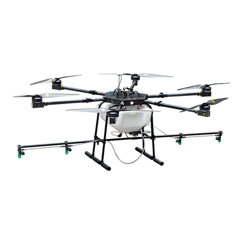
Impossible US-1 User manual

US-1 Operating Handbook
Version 3.0
Impossible Aerospace
2222 Ronald Street, Santa Clara, CA, 95050
650-262-7184
November 22, 2019
1

Contents
1 Safety 4
2 Technical Support 4
3 About US-1 4
3.1 US-1 Specifications . . . . . . . . . . . . . . . . . . . . 6
3.2 US-1Handset........................ 6
3.3 Flir Duo Pro R (Optional Accessory) . . . . . . . . . . . 8
3.3.1 Flir Duo Pro R Configuration . . . . . . . . . . . 9
3.4 US-1 Case Contents . . . . . . . . . . . . . . . . . . . . 9
3.5 AboutIAGS......................... 11
4 US-1 First Time Setup 11
4.1 Propeller Installation . . . . . . . . . . . . . . . . . . . 11
4.2 InitialCharge........................ 12
4.3 FirstPreflight........................ 12
5 Charging 12
5.1 ChargingSafety ...................... 12
5.2 ChargingUS-1 ....................... 13
5.3 Charging The Handset and Tablet . . . . . . . . . . . . 14
5.4 US-1 Storage Requirements . . . . . . . . . . . . . . . 14
6 Preflighting US-1 14
6.1 US-1 Ground Handling Safety . . . . . . . . . . . . . . 14
6.2 Aircraft Setup and Pre-Flight Checks . . . . . . . . . . 14
6.3 DeployingUS-1....................... 15
6.4 InspectingUS-1 ...................... 15
6.5 PoweringOn ........................ 16
6.6 Compass Check and Calibration . . . . . . . . . . . . . 16
6.7 Checking Safety Settings . . . . . . . . . . . . . . . . . 17
6.8 Starting Recording . . . . . . . . . . . . . . . . . . . . . 19
7 Flying US-1 19
7.1 US-1 Flight Modes . . . . . . . . . . . . . . . . . . . . . 19
7.2 Arming and Taking off . . . . . . . . . . . . . . . . . . . 19
7.3 Controlling US-1 in Flight . . . . . . . . . . . . . . . . 20
2

7.4 LandingUS-1........................ 21
7.5 Operating the FLIR Camera and Gimbal . . . . . . . . 21
7.6 US-1 Autonomous Flight . . . . . . . . . . . . . . . . . 22
7.6.1 AutoTakeoff..................... 22
7.6.2 Auto Landing . . . . . . . . . . . . . . . . . . . . 23
7.6.3 Auto Return to Launch . . . . . . . . . . . . . . 23
7.6.4 Auto Altitude Change . . . . . . . . . . . . . . . 23
7.6.5 Go to Location . . . . . . . . . . . . . . . . . . . 24
7.6.6 Mission Planning . . . . . . . . . . . . . . . . . . 24
7.7 US-1 Battery Management . . . . . . . . . . . . . . . . 25
7.8 StowingUS-1........................ 25
8 US-1 Operational Limitations 26
8.1 Wind............................. 26
8.2 Rain ............................. 26
8.3 Temperature ........................ 26
9 Emergency Procedures 27
9.1 Flyaway Procedures . . . . . . . . . . . . . . . . . . . . 27
9.2 Post-Crash Procedures . . . . . . . . . . . . . . . . . . 27
10 Troubleshooting 28
10.1US-1 does not connect to Handset . . . . . . . . . . . . 28
10.2US-1 does not charge . . . . . . . . . . . . . . . . . . . 28
10.3Updating US-1’s Firmware . . . . . . . . . . . . . . . . 29
11 COA Application Information 29
12 Legal Information 30
12.1General Information . . . . . . . . . . . . . . . . . . . . 30
12.2Applicable Regulations . . . . . . . . . . . . . . . . . . 30
12.3Warranty .......................... 30
12.4LogUploads......................... 30
12.5Limitation of Liability . . . . . . . . . . . . . . . . . . . 31
12.6Copyrights ......................... 31
3

1 Safety
The Impossible US-1 is a high performance electric aircraft intended
for operation by trained pilots. The aircraft presents several safety
risks beyond those of a lightweight consumer drone.
With the standard payload option, the aircraft weighs approxi-
mately 20 pounds. A falling vehicle can cause significant damage.
When spinning, the large aircraft propellers are difficult to see and
pose a significant hazard to nearby personnel. In addition, the fully-
charged aircraft contains 1.2 kilowatt-hours of energy - an amount
of energy equivalent to a kilogram of TNT.
US-1 can be safely stored, charged, transported, and flown when
proper procedures are followed by a qualified operator. While this
handbook is a compendium of relevant information, it is ultimately
the operator’s responsibility to ensure they have the necessary train-
ing to safely operate the vehicle. Operators must familiarize with
not only this manual but also any applicable Impossible Aerospace
service bulletins before flying.
When operating the US-1 in U.S. Airspace, always operate within
the restrictions specified within Part 107 or an applicable COA.
When operating outside of U.S. airspace, please confer with the rel-
evant aviation authorities prior to conducting flight operations.
2 Technical Support
For any questions or concerns regarding US-1, please contact Im-
possible Aerospace’s technical support team at support@impossible.aero,
or by phone at (408) 675-1195.
3 About US-1
The Impossible US-1 is an unmanned aircraft built to provide situa-
tional awareness and aerial reconnaissance. Carrying our standard
payload, the US-1 offers up to 78 minutes of flight time. The US-
1 airframe is engineered, assembled, and supported in the United
States at our headquarters in Santa Clara, CA.
4

1. Power Button
2. Gimbal Attachment
3. Charge Connector
4. Landing Feet (4X)
5. Clockwise Propellers (2x)
6. Counterclockwise Propellers (2x)
5

3.1 US-1 Specifications
External Dimensions (Propellers Folded) 26” x 26” x 16”
Unladen Weight 18.5 lbs
Maximum Flight Time with Payload 78 minutes
Maximum Airspeed - Position Mode 18 MPH
Maximum Airspeed - Altitude Mode 45 MPH
Maximum Tilt Angle 35 Degrees
Maximum Range 29 Miles
Maximum Density Altitude 8,200 ft (2500 m)
Maximum Radio Range Up to 2 miles
3.2 US-1 Handset
The US-1 handset is an all-in-one radio for control, telemetry and
HD video, capable of ranges up to 2 miles. The handset is equipped
with 6 auxiliary switches and 2 rotary dials to accommodate the US-
1’s many functions. The handset also features a full size HDMI port
for live video output. The handset connects to an included Android
tablet running Impossible Aerospace Ground Station (IAGS).
6

1. Gimbal Tilt Dial
2. Gimbal Pan Dial
3. Gimbal Mode Switch
4. Return to Home Switch
5. Left Control Stick
6. Right Control Stick
7. Camera Function Switches (F1-F3)
8. Charge Indicator
9. Charge Port
10. Power Switch
11. HDMI Port
12. USB Connection to Tablet
13. Position / Altitude Mode Switch
7

3.3 Flir Duo Pro R (Optional Accessory)
The FLIR Duo Pro R and Gimbal optionally delivered with US-1 are
pre-balanced and ready to support flight operations. The Flir Duo
Pro R comes with two microSD cards. Prior to each flight, ensure
that the cards are emptied and inserted to enable data collection.
To review data from a flight recording, simply remove the microSD
cards and import the data to your computer or preferred storage
platform.
For more information about the FLIR Duo Pro R, please reference
the device’s manual, available on the FLIR website.
1. Camera Record Button
2. Bluetooth Enable Button
3. 2X SD card Ports
4. Camera Status Light
8

3.3.1 Flir Duo Pro R Configuration
The FLIR Duo Pro R settings are configurable via the FLIR UAS
Mobile Application, available on the Android and iOS App stores.
The settings are configured by Impossible Aerospace to the defaults
specified in section 7.5.
To setup your FLIR functions:
1. Power on the Vehicle as described in Section 6.5
2. Ensure the camera status light on the fron of the camera is
blue. Press the Bluetooth button on the camera if the light is
green.
3. Navigate to the ”Connect” tab of the FLIR UAS App.
4. Press ’Accessory Port’
•The ’Display Video Mode’ Function on PWM1 changes the
functions of the F3 switch’s three positions.
•The ’IR Color Pallete’ Function on PWM2 changes the color
pallets selected by the F2 switch’s three positions.
•The Visible Zoom Function on PWM3 changes the digital
zoom settings. The ’Mid’ State is not currently utilized.
The ’Low’ and ’High’ settings set the default and zoom state
of the camera, which are selected by the F1 switch.
3.4 US-1 Case Contents
The US-1 comes equipped with tools, accessories, and shipping pro-
tectors. If the US-1 is to be shipped or handled roughly in the fu-
ture, keep the foam shipping protectors that come with the vehicle.
9

1. 1x US-1 Airframe with Propellers
2. 4x Landing Gear Feet
3. 1x Hardshell Carrying Case
4. 1x Flir Duo Pro R with Gimbal
5. 2x 64Gb MicroSD Cards
6. 1x Remote Control Handset
7. 1x Handset Charger
8. 1x Samsung Galaxy S5E Tablet
9. 1x Samsung Galaxy S5E Charger
10. 1x US-1 Delta-Q Charger
11. 1x Torque Driver for Propellers
12. 1x Set of Propeller Screws
13. 2x Handset Antennas
10

14. 4x Foam US-1 Shipping Protectors (Not Pictured)
3.5 About IAGS
The Impossible Aerospace Ground Station (IAGS) provides complete
flight control, telemetry and HD video decoding during flight. Mis-
sion planning is included for autonomous operations and repeat-
able flight patterns. For more about IAGS, please see section 7.
4 US-1 First Time Setup
4.1 Propeller Installation
The US-1 is shipped without propellers to prevent damage during
shipping. Two clockwise and two counter-clockwise propellers must
each be installed on the correct arms. The counterclockwise pro-
pellers are marked with silver at the center of the propeller hub,
and are installed on US-1’s the front right and back left arms, as
indicated in section 3.
To install each propeller, use 2 propeller screws and the included
torque driver. The torque driver is preset to the correct value of 1.2
N-m.
Follow the following procedure to install propellers:
1. Using the torque driver, install each screw and tighten until
the propeller is fully seated.
2. Use the torque driver to tighten one screw a quarter turn.
3. Switch to the other screw and tighten a quarter turn.
4. Repeat steps two and three until the torque driver handle clicks
loudly and temporarily breaks free on one of the screws.
5. Switch to the other screw and tighten until the torque driver
handle clicks loudly and temporarily breaks free.
Be certain to properly torque propeller screws. Turn until the
torque driver clicks and stop turning. Under or over torqued pro-
pellers represent a significant hazard and could come off in flight.
11

4.2 Initial Charge
US-1 does away with replaceable battery packs by integrating the
battery with the airframe structure. US-1 is shipped 30% charged.
Before use, charge US-1 to 100% by following the charging proce-
dure outlined in Section 5.
4.3 First Preflight
A first preflight with US-1 should performed as specified in Section
6. Note that if the vehicle is being deployed more than 50 miles
from Santa Clara, where it was factory calibrated, it will require a
compass calibration as outlined in 6.6.
5 Charging
5.1 Charging Safety
Charging US-1 with damaged or improper equipment can result in
a fire. Before charging US-1, ensure that the charger, charge con-
nector, and vehicle are undamaged and unmodified. Do not charge
US-1 if the vehicle has suffered crash damage. Do not charge US-1
with any charger other than the one provided. Remove any non-
standard payloads before charging US-1.
A grounded outlet is required to reduce the risk of electric shock.
Do not use ground adapters or modify the charge plug in any way.
Only one charger may be operated on a single 15 amp household
circuit at a time.
The charger may become hot during charging. Provide at least
1” clearance on all sides of the charger and aircraft during active
charging and use hand protection to safely handle the charger dur-
ing or immediately after operation. Do not charge US-1 inside of
the hard-shell carrying case.
12

5.2 Charging US-1
US-1 can be safely charged when the battery cells are between 32◦
F and 104◦F. Should the cells be too cold or too warm, the charger
will turn off. The vehicle will resume charging onche cells are within
the above temperature range.
At the 25A standard charge rate, US-1 will charge from 0% to
75% in 91 minutes and from 0% to 100% in 144 minutes.
To charge US-1:
1. Plug the charger into a standard wall outlet. The blue power
icon on the charger will light up, indicating the charger is on.
2. Locate the magnetic charging ports on the side of US-1.
3. Connect the round magnetic plug from the charger to the un-
covered port. It will snap into place once the magnets are
aligned. Once connected, the LEDs on US-1 will turn purple.
4. During charging, the LEDs on the drone will flash purple. The
orange lighting bolt icon on the charger will illuminate, indi-
cating the charger is active.
5. The battery charge indicator on the charger will indicate the
state of charge of the US-1.
(a) If the bottom LED is blinking green, the vehicle is less
than 80% charged.
(b) If the bottom LED is solid and the top is blinking green,
the vehicle is between 80% charged and full.
(c) If both LEDs are solid, the vehicle is fully charged. In
addition, the LEDs on the drone will turn green and the
orange ligning bolt on the charger will turn off, indicating
the charger is no longer active.
If the yellow triangle on the charger continues to blink after charging
begins, there is an error. Please refer to the troubleshooting section
of this handbook.
13

5.3 Charging The Handset and Tablet
The Galaxy S5E tablet can be charged using any USB-C charger,
one of which is included with US-1. To charge the S5E, disconnect
the tablet from the handset and connect it to the charger.
The handset can be charged using the included 12v charger. To
charge the handset, turn the handset off and plug the charger into
the receptacle on the back right corner of the handset.
5.4 US-1 Storage Requirements
Lithium - Ion batteries can be damaged by long-term storage at an
extremely low state of charge. Impossible Aerospace recommends
storing US-1 plugged into its charger.
If long-term storage without use is intended or it is necessary to
ship the vehicle, contact Impossible Aerospace technical support at
6 Preflighting US-1
6.1 US-1 Ground Handling Safety
The US-1 in its hardshell case with charger weighs roughly 75 pounds.
Be certain to maneuver the case and its contents with two people
to limit the risk of injury. When moving US-1 outside of its case,
grasp the vehicle firmly with both hands. In the event of an acci-
dental drop while handling the vehicle on the ground, inspect the
vehicle for damage and, if any is found, follow the post-crash emer-
gency procedures.
US-1’s propellers start spinning the moment the aircraft is armed.
Assume a vehicle that is turned on could be armed at any time. Do
not linger within the radius of the propellers.
6.2 Aircraft Setup and Pre-Flight Checks
A thorough preflight is essential to safe flight operations. The use of
a pre-flight checklist, such as the one included with US-1, will help
14

an operator to ensure that each part of the preflight is completed
every time.
6.3 Deploying US-1
1. Gently lift the US-1 out of its case and place it on its side.
2. Unfold each leg and attach the feet. Attach each foot to the
inner leg first, then the outer leg. Ensure the detents click
into place.
3. Unfold the propellers. They will click into place when they are
properly centered.
4. If so equipped, connect the gimbal and camera assembly to
the collar on the bottom of the aircraft. Lock the collar into
place by twisting the collar clockwise until a click is heard and
felt.
5. Move the US-1 to a safe take-off location, with 20 feet of clear-
ance in all directions.
6. Remove the handset from the carrying case. Install the tablet
and antennae and connect the USB cable.
6.4 Inspecting US-1
1. With the US-1 powered off, visually inspect the aircraft for
damage, particularly the propellers, landing gear, and land-
ing gear feet.
2. Inspect the four motor and two propeller screws, ensuring that
the torque stripe shows the screw has not rotated.
3. Ensure that the gimbal is securely attached to the vehicle and
the locking collar is firmly locked.
4. Check that the desired SD cards are installed in the FLIR cam-
era.
5. Remove the lens caps of the camera.
15

6.5 Powering On
1. To power on US-1, press and hold the black power button.
2. To power on the handset, slide the switch on the bottom right
of the handset to the ‘ON’ position.
3. Ensure the tablet is powered on and the USB cable is con-
nected to the handset, and launch the IAGS application.
4. Within IAGS, check for connection to the aircraft.
5. When connection is verified, verify the state of charge of the
Aircraft, Handset, and Tablet are sufficient for the intended
mission. For more on Aircraft Battery Management, see sec-
tion 7.7.
6. Toggle each switch on the handset and check for the expected
behaviors.For more on handset functions, refer to sections 7.3
and 7.5.
7. Verify that camera settings are sufficient for the intended mis-
sion. For more on camera settings , refer to section 3.3.1.
8. Wait for US-1’s GPS to connect; this will be indicated when
Position mode becomes available.
6.6 Compass Check and Calibration
The US-1 uses an internal compass as a stabilization reference. If
the aircraft has moved more than 50 miles since the compass was
last calibrated or is operating in an environment with high magnetic
noise, the compass may require recalibration. To check if the com-
pass is calibrated, point the front of the aircraft towards geographic
north and verify the aircraft’s heading in IAGS. Next, rotate the air-
craft 90 degrees to point to the east or west and verify the aircraft’s
heading again. If either heading is changing or varies by more than
12 degrees in 30 seconds, the compass requires re-calibration.
Impossible Aerospace recommends calibrating the aircraft with
the propellers folded and secured by rubber bands.
To calibrate the compass:
16

1. Click on the Gear Icon at the top left of IAGS, while connected
to the aircraft.
2. Click on the ’Sensors’ tab on the left drop down menu.
3. Hit the ’Compass’ button at the top of the sensor list.
4. ’Calibrate Compass’ will be listed on the top right of the screen.
(a) Verify The Autopilot Orientation reads “ROTATION YAW 135”
(b) Verify The External Compass Orientation reads “ROTA-
TION YAW 270”
5. Press ’OK’ to begin calibration.
6. Perform each of the Calibration actions by orienting US-1 and
rotating slowly and continuously in the direction shown in
IAGS. Each will appear outlined in red if the action has not
yet been completed, yellow if the action is in progress , and
green when the action has been completed.
Remember that the back of the US-1 is the side of the airframe
with the power button; this should correspond to the tail of the
small airplane shown during calibration.
6.7 Checking Safety Settings
US-1 was designed with the capability to return to the launch site
in the event of a loss of communication with the vehicle or critically
low battery voltage. To verify these settings:
1. Press the menu button, indicated by three horizontal lines, in
the top left corner of IAGS.
2. Press ’Vehicle Setup’.
3. Navigate to ’Safety’.
•The Low Battery Failsafe Trigger determines the response
when the aircraft battery is critically low. The failsafe will
activate twice, once at the ’failsafe’ level and again at the
’emergency’ level.
17

(a) Ensure the Failsafe Action is set to ”Return Mode”.
(b) Ensure the Battery Warn Level is set as desired (20%
recommended).
(c) Ensure the Battery Failsafe Level is set as desired (15%
recommended).
(d) Ensure the Battery Emergency Level is set as desired
(5% recommended).
•The RC Loss Failsafe Trigger determines the response when
the aircraft loses RC communication.
(a) Ensure the failsafe action is set to ”Return Mode”.
(b) Ensure the RC Loss Timeout is set to 0.5 seconds.
•The Data Link Loss Failsafe Trigger determines the re-
sponse when the handset loses vehicle telemetry.
(a) Ensure the failsafe action is set to ”Disabled”.
•The Geofence Failsafe Trigger determines the response when
the vehicle breaches a geofence.
(a) Ensure the action on breach is set to ”Hold Mode”
•The Return Home Settings determine the exact Return to
Launch Behavior.
(a) Ensure the altitude is sufficient to avoid obstacles en
route.
(b) Ensure the vehicle is set to Return Home, then Land
immediately.
•The Land Mode Settings determine the automated landing
behavior.
(a) Ensure the Descent Rate is set to 2 mph. Faster de-
scent risks damage to the vehicle landing gear.
(b) Ensure ’Disarm After’ is checked and the time is set to
1 second.
•Vehicle Telemetry Logging determines whether telemetry
is saved to the vehicle. Ensure this setting is turned on.
18

6.8 Starting Recording
While IAGS is capable of recording the transmitted video stream,
US-1’s FLIR camera has the capability to record high-definition
video onboard. If desired, start recording on the FLIR by pressing
the physical ‘record’ button on top of the camera.
Alternately, recording can be started by connecting to the FLIR
with the UAS app as described in section 3.3.1.
7 Flying US-1
7.1 US-1 Flight Modes
US-1 has two available flight modes, controlled via the flight mode
switch on the left hand side of the controller.
•Position Hold is activated when the handset’s flight mode switch
is in the forward or away position. This mode is to be used for
all take-offs, landings and GPS assisted flights.
•Altitude Hold is activated when the handset’s Flight mode switch
is in the near position. This mode is intended to be used when
GPS signal is unavailable. In Altitude mode, the vehicle will
drift with the wind and the pilot is responsible for position
control.
•Before takeoff, ensure that the aircraft has GPS connection
and position mode is activated.
7.2 Arming and Taking off
Arming US-1 starts the propellers spinning and allows the vehicle
to take off. If US-1 is armed but no takeoff is performed, the vehicle
will disarm after roughly 8 seconds.
Before arming:
1. Tilt the Gimbal up to protect the camera from debris.
2. Verify the preflight has been completed.
19

3. Confirm the takeoff location is clear of bystanders or obstacles.
4. Confirm the propellers are clear of obstruction.
5. Audibly declare ‘Arming’ to anyone in earshot.
To arm the aircraft and take off:
1. Move the left control stick to the bottom right corner and hold
it there until the propellers begin spinning.
2. Verify the propellers are spinning in the proper direction as
per the diagram in section 3.
3. To take off, advance the left stick away from the operator until
the aircraft becomes airborne.
7.3 Controlling US-1 in Flight
In Position Hold mode, the aircraft will not move or drift when the
sticks are centered.
•The left stick vertical axis, or throttle, controls altitude. To
climb, move the left stick away from the operator. To descend,
move the left stick towards the operator.
•The left stick horizontal axis controls yaw. To rotate the aircraft
to the left, move the left stick to the left. To rotate the aircraft
to the right, move the left stick to the right.
•The right stick vertical axis controls pitch. To move the aircraft
forward, move the right stick forward. To move the aircraft
backwards, move the right stick backwards.
•The right stick horizontal axis controls roll. To move the air-
craft to the left, move the right stick to the left. To move the
aircraft to the right, move the right stick to the right.
•Remember that flight controls are relative to the vehicle head-
ing, not the pilot. Pitching the aircraft forward will move the
aircraft in the direction it is pointing, not in the direction the
pilot is facing.
20
Table of contents
