Night Watcher nw1003X Installation instructions

1
Motion tracking
sensor halogen light
Installation & operating manual
NIGHTWATCHER SUR EILLANCE PLUS
Wireless Handheld monitor
Model no:
nw1003X

2
INTRODUCTION
Congratulations on the purchase of your new Nightwatcher Security Light. Before installation of the
unit, please read the operating instructions and safeguards carefully. It is important that you read and
follow the instructions in the manual, even if you feel you are familiar with this type of product.
SPECIFICATIONS
Model Number:
NW1 3x
AC Input:
22 -24 V 5 Hz
Time Adjustment:
3 / 6 Seconds
Sensor Range:
1 m x 21 °
Power Consumption:
15 Watts
IP Weather Rating:
IP54
Lamp:
15 , J type Halogen Lamp
Camera:
Color CMOS image sensor
View angle 6 °
Transmission frequency: ISM 2.4GHz ARIB-T66
Sensiti ity Adjustment:
5m / 1 m
Operation Temperature:
°
~ + 5
°
IMPORTANT SAFEGUARDS
WHEN USING ELECTRICAL APPLIANCES, IN ORDER TO REDUCE THE RISK OF FIRE,
ELECTRIC SHOCK, AND/OR INJURY, THESE BASIC SAFETY PRECAUTIONS SHOULD
ALWAYS BE FOLLOWED:
FOR YOUR SAFETY
Read all instructions carefully, even if you feel you are quite familiar with the appliance.
• Any alterations or additions to building wiring, must be completed by a licensed electrical mechanic, or
person authorised by legislation to work on the fixed wiring of any electrical installation
• To prevent electric shock, please ensure that power is disconnected before installing.
• The appliance is not intended for use by children or infirm persons without supervision.
• Children should be supervised to ensure that they do not play with the appliance.
• This unit must be connected to a 22 -24 V 5 Hz power source
• The lamp must be earthed
• The cable installed shall be 3 x 1. mm² at least
• The unit is for outdoor use only
• The unit is for wall mounting
COMPULSORY WARNING
Note: No user serviceable parts inside. The Halogen Lamp is the only part that can be replaced. Unauthorised
modification voids warranty, Return to place of purchase for replacement or service under warranty.
SAVE THESE INSTRUCTIONS

3
O ER IEW
INSTALLING THE BULB
Unscrew the lamp cover of the fitting and install a 15 W J-type lamp.
Re-fit the lamp cover and tighten the screws.
IMPORTANT: THE INTALLATION OF THIS FITTING MUST BE DONE BY A QUALIFIED ELECTRICIAN.
This fitting must be earthed.
Do not mount the light against near flammable surfaces.
The motion detector will not operate correctly if it is installed:
() Near the outlet of a central heating boiler
() Near air conditioning plant
() Pointing directly at moving vehicles
() Within sight of reflection from moving water
() Where other lamps could shine onto the detector
The maximum rating of this light is 15 Watts. Check that the total load of the circuit. Including this luminaire. Does
not exceed the rating of the circuit cable.
NOTE: This highly responsive unit may occasionally activate due to rapid environmental changes. Allow for approximately
3 seconds warm-
up time before the sensor resumes normal activity.
FFhg
G
G
G
Gg
G
Video Camera
Sensor
LED indicator
Dip Switch
Antenna
Front housing
Lamp 15 W
Lamp Cover
WARNING ! ! !
BEFORE ATTEMPTING ANY INSTALLATION OR
MAINTENANCE, ENSURE THAT THE
ELECTRICAL SUPPLY IS SWITCHED OFF AND
THE CIRCUIT FUSES REMOVED OR THE
CIRCUIT BREAKER IS IN THE “OFF”POSITION.

4
MOUNTING THE FITTING
To ensure correct operation of the sensor, mount the fitting where traffic passes across the detector.
SETTING THE LIGHT UP TIME & SENSITI TY
Remove the back mounting box from the fixture by unscrewing the screw at the bottom.
Set the Light up time & Sensitivity you preferred
1 : Light up time (OFF:3 seconds/ON:6 seconds)
2 : Sensitivity (OFF:5m/ON:1 m)
Re-fit the back mounting box and tighten the screw.
WIRING INSTRUCTIONS
Feed the cable through the back mounting box
and bush the cable entry to avoid abrasion to
the cable.
Connect the earth wire to the connector
opposite the green/yellow cable.
Connect the brown phase conductor active to
the connector opposite the brown cable and
tighten the screws.
Connect the blue neutral conductor to the
connector opposite the blue cable and tighten
the screws.
Check that all connections are correct and tight, as any misconnections will damage the detector.
Re-fit the fitting to the back mounting box.
TOP VIEW
GOOD SENSITIVITY
LESS SENSITIVITY

5
FUNCTION
This light is equipped with 3 motion sensors: zone 1 covers 6 degree; zone 2 covers 1 degrees and zone 3
covers 6 degrees.
22 degrees (maximum) in total for 3 zones.
The light will switch on for 3 /6 seconds and off automatically when heat/ movement is detected.
The factory default: the mode is「Auto mode」for night time operation, camera works all day.
To change the mode to night time only (Auto mode), push the button at the bottom of the housing and the
hidden LED indicator will turn off at this mode. The light will be on at 3 /6 seconds when detecting any
movement at night.
Push-button for programmable functions:
- Test mode: light and camera work all day
- Auto mode: light works at night, camera works all day
Reset function: If the stepper motor of tracking light works abnormally, the hidden LED indicator will flash
red and the light will stop turning automatically. In Test mode, the red LED will flash for 3 times and off for
5 seconds; in “Normal mode”, the red light will flash in a regular pattern. Please simply switch off and on
the main power to resume the tracking light. Below are the possible abnormal situations.
- External force: the light head is blocked by objects or is blown by strong wind and is unable to turn
properly, the hidden LED will flash in red to signal users the abnormal situation.
- Stepper motor: when the stepper motor has reached the end of its life time or is damaged, the hidden LED
will flash in red to signal users the abnormal situation. Please switch off and on the main power, the
tracking light now may or may not resume its operation. If the stepper motor stops working, NW
Surveillance Plus becomes a regular motion sensor security light.
Left Right 70°
°°
°
Hidden LED
ZONE 1
ZONE 2
ZONE 3
TOTAL DETECTION RANGE
Push-button
LED indicator

6
OPERATION
1. Insert the plug to activate the light, the light is now under Test mode: light works on day and night
NOTE: Allow for approximately 3 seconds warm-up time before the sensor resumes normal activity.
2. To test, walk through the sensor’s detection area.
3. Movement will activate the sensor and turn the light on; the light will turn to the detected zone automatically.
4. After the light is activated, keep out of the detection area and the light will switch off automatically after
light up time (3 /6 seconds). The light will be activated again when detecting any movement.
If there is continuing movement in the detection zone, the light will stay on until movement ceases. (After
light up time)
LAMP REPLACEMENT
To isolate the unit, first switch off the unit from the mains power. Allow bulb to cool before attempting to
remove it. Unscrew the lamp cover and take the old lamp out and replace with a new one, close the lamp
cover and tighten the screws.
WARNING: This fitting will become hot when in use. Allow bulb to cool before touching.
CLEANING
• Before Cleaning make sure that the power is cut off and allow to cool before commencing.
• Care must be taken while cleaning to avoid scratching the fitting and glass. A soft cloth or a fine hair brush should
be used with a non-abrasive cleaner.
DO NOT use sol ents or abrasi e cleaners on any part of the Nightwatcher.
NOTE: THE INTELLIGENT MOTION SENSOR TRACKING LIGHT IS DESIGNED TO ILLUMINATE
WHEN THE DETECTION AREA IS ENTERED BY A PERSON AND WILL DETECT A MOVING
HEAT SOURCE. THERE IS NO GUARANTEE IMPLIED THAT IT WILL PROVIDE TOTAL
SECURITY OR PREVENT ILLEGAL ENTRY.

7
NIGHTWATCHER SUR EILLANCE PLUS
Wireless Handheld monitor
I. O ER IEW OF AEC-711C
II. ASSEMBLY INSTRUCTION
1. Install 3pcs NI-MH rechargeable batteries to the battery compartment with its polarities
matched.
Note:
- This receiver can also be powered on by adapter (DC 6V 1.5A).
- The rechargeable battery will be charged after the adapter is plugged in, and the charge indicator
lights up during charging and will turn off after a full charge.
- A full charge will take about 6 hours, which can power the receiver for about 4 hours
continuously.
- You are recommended to have the battery fully charged before its first installation to optimize its life.
- Do not burn or disassemble the rechargeable battery.
- Do not short-circuit the battery; it may cause fire or electric shock.
2. Push the power switch to ON position.
Battery case
Rechargeable
battery (inside)
LCD
LCD/TV Button
MENU Button
OK Button
Channel Button
Buzzer
Antenna
LED indicator
Power switch
Video Output
Power Socket
Holder
View Button (1/4)
(Single/Quad)

8
3 . Set the channel of receiver same as that of NW22 2 by pressing the channel button continuously, and the pictures are
displayed on the monitor/TV.
- Press “MENU Button” then press hannel Button to select “MONITOR” and press “OK button”.
- Press “ hannel Button” to select”Pair am” and then press “OK button”.
- There is”1 2 3 4” shown on the L D, to select which number of channel you want to set up this fitting. Within 10 seconds, press
“ hannel Button” to select the number of the channel you want then press”OK button”. Within 10 seconds, press the “Dip Switch”
on the fitting and when you see detecting image displayed on the L D, it means the channel setting is completed. If it shows “No
onnection”, repeat these steps again.
- For other three different fittings, repeat the above same steps to set up the different channel. Press”View Button” for Quad View
condition, you can see 4-split view from 4 different fittings.
NOTE: 1. when you make the channel setting, L D must be under “Single View” condition.
2. Before setting the channel between the fitting and L D, press “Push-button” switch on the bottom of the fitting firstly, the
stepper motor will stop working (the RED LED will keep flashing) in order to keep “Dip Switch” on the fitting not moving and can be
easily pressed when setting up the channel later.
4. for more clear pictures or record image:
○
1Please connect the receiver to a TV with video cable.
○
2 Please connect the receiver to a TV and a video recorder with video cable.
G
G
G
LCD/TV Button
○
1
○
2

9
III. OPERATION
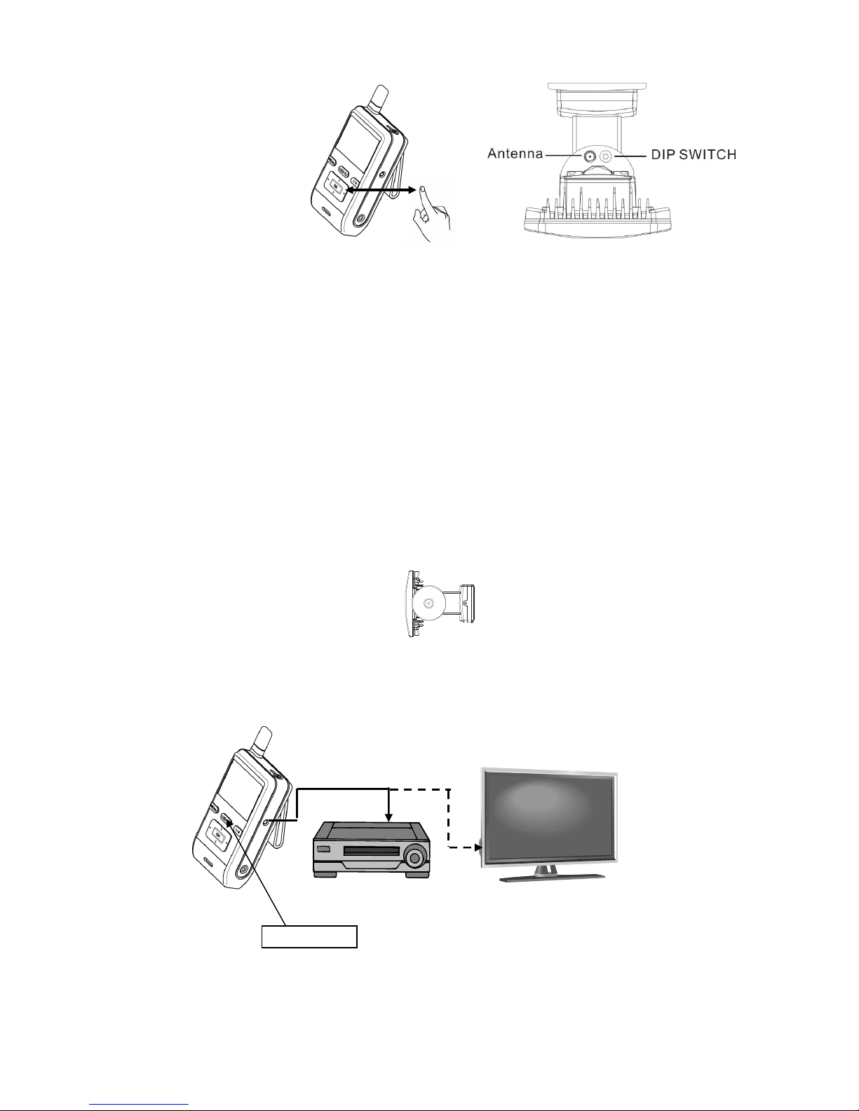
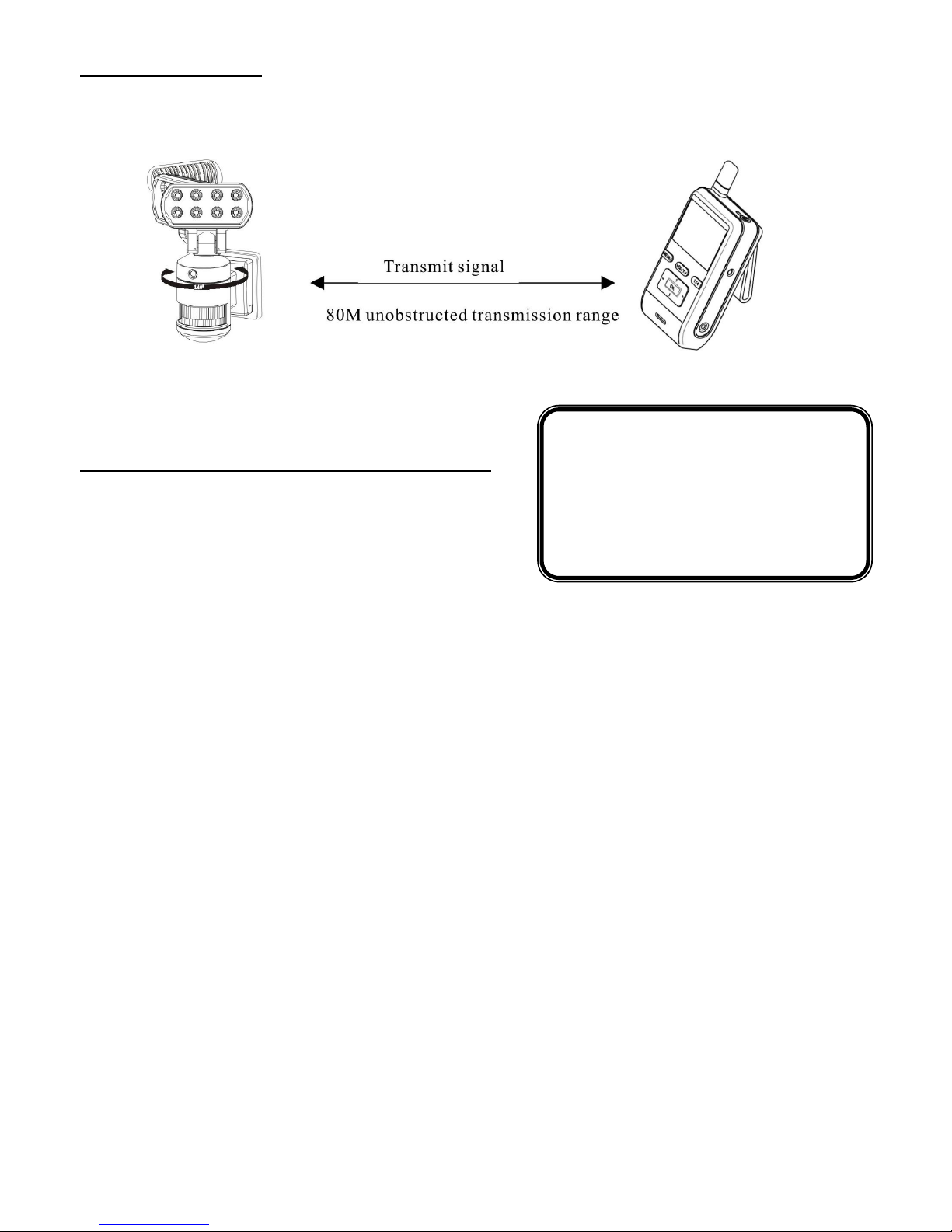
When NW22 2 detects any movement, the wireless LCD monitor is triggered for 30/60 seconds image at the same time. The
unobstructed transmission effective range is about 8 meters, but actual transmission range may vary according to
weather, location, interference and building. One wireless LCD monitor is possible to display 4 camera images.
OPERATION OF WIRELESS
HANDHELD SCREEN RECEI ER
1. LCD image display: push view button「1/4」for image display
-Single View: single CAMERA view (initial image<original default>)
display image from one camera at one time
-Quad View : 4 split view (able to connect 4 CAMERAS and
display 4 images on screen at the same time)
☆When SENSOR is triggered, the monitor will sound ”BEEP”
(“BEEP” is set “ON” condition)
No. 1 sensor light detects motions, sound”BEEP” once
No. 2 sensor light detects motions, sound”BEEP-BEEP” twice
No. 3 sensor light detects motions, sound”BEEP-BEEP-BEEP”3 times
No. 4 sensor light detects motions, sound”BEEP-BEEP-BEEP-BEEP” 4 times
☆BEEP will sound continuously for 2 times and stops if there is no further detection.
During 2 times of BEEP if this unit detects any motions, it will recount for 2 times.
☆ Push any of the buttons to stop”BEEP”.
☆When BEEP is set “OFF”, there will be no sound.
☆「View Mode」is set”MENU”(manual) , the number of camera will flash under quad-view.
2. Function settings:push “MENU “button to choose settings.
IMPORTANT
IMPORTANTIMPORTANT
IMPORTANT
This is only for connecting 1 CAMERA.
For connecting several CAMERAS, make sure to return
to quad-view after finishing setting in single view.

10
-CAMERA:
-MONITOR:
Beep:ON/OFF(original default ON) When SENSOR detects motions, monitor will
beep.
Beep Vol:High/Low(original default High) Volume adjustment for beep
Brightness:~1 ( original default 5) LCD brightness adjustment
OSD Disp:ON/OFF Date and antenna icon display set
View Mode:AUTO/MENU( original default
AUTO)
Single view and quad-view setting
(AUTO/MENU):
Under AUTO mode, single view will return to
quad-view automatically 2 seconds later;under
MENU mode, please switch from single view to
quad-view by manual.
Under MENU mode, if switch to single view,
there will no display on the screen if other sensor
lights detect motions.
Scan time:OFF/5SEC/1 SEC/15SEC
(original default OFF)
Looping function, 4 CAMERAS display single
view on the screen in order.
Pair Cam:1/2/3/4 Register CAMERA ID。(up to 4 CAMERAS)
Version:software program version
Reset:YES/NO Back to original default.
-Other:Date/Time:set time and date
CHARGE
Cam1 EV:-
2. ~+2.
Cam2 EV:-2. ~+2.
Cam3 EV:-2. ~+2.
Cam4 EV:-2. ~+2.
Set the brightness of CAMERA. Standard value is
, turn the knob to”-“side to reduce the brightness,
turn the knob to”+”side to increase the brightness.
Before attempting any setting, please power sensor
light. For multiple cameras, the brightness of each
CAMERA may be different, please adjust the
brightness to preferred value.
(Every adjustment value is .5. Original default is .)
Freq:5 / 6 Hz
Version:software program version
Reset:Yes/No Back to original default.
IMPORTANT
IMPORTANTIMPORTANT
IMPORTANT
Before registering ID, please push the
bottom button to stop sensor light
turning.

11
When connect Wireless Handheld Screen Receiver to AC ADAPTER, it will
charge batteries automatically.
Under charge, LED turns red color.
Charge time:6 hours max.
Red LED:charge
Red LED flashes:abnormal charge
※Under abnormal charge, please remove AC ADAPTER and check if
batteries are placed correctly.
REPLACE BATTERIES
Battery used:AA NI-MH 26 mAh rechargeable battery 3PCS
1. Take old batteries out.
2. Place new batteries into battery case see right side figure
-Make sure the polarity is aligned correctly
- Please replace 3 batteries together
PRODUCT WARRANTY
1 YEAR REPLACEMENT WARRANTY
Your Nightwatcher Security Light is covered for a
Period of 12 months from your
Date of Purchase.
THIS WARRANTY FORM SHOULD BE RETAINED
BY THE CUSTOMER AT ALL TIMES.
WARNING
The followin actions will result in the warranty
IMPORTANT
IMPORTANTIMPORTANT
IMPORTANT
DO NOT USE PRIMARY BATTERY!
Such as Manganese electric battery 、Alkaline
electric battery and oxy ride electric battery to
prevent hazard like leakage and crack.
LED indicator

12
The Warranty covers faulty parts or workmanship.
The warranty is only made a ailable by returning
the product to your point of purchase with your
receipt.
PURCHASED FROM:
DATE OF PURCHASE:
PRODUCT SERIAL #:
bein void:
• If the product has been operated on a supply
voltage other than that specified on the unit
• If the product shows signs of damage or defects
caused by or resulting from abuse.
• If the product ahs been disassembled or tempered
with in any way.
• If the product is not drilled, mounted and used in
accordance with the instructions.
•
Note: Warranty excludes consumable parts such as tubes,
globes and batteries.
YOUR WARRANTY FORM SHOULD BE RETAINED BY YOU AT ALL TIMES.
SHOULD YOU HAVE ANY QUESTIONS PRIOR TO RETURNING YOUR PRODUCT
FOR WARRANTY OR REPAIR PLEASE TELEPHONE OUR CUSTOMER SERVICE
HELPLINE:
CUSTOMER SERVICE: 1300 281 005
TO ENSURE A QUICK RESPONSE PLEASE HAVE THE MODEL NUMBER, SERIAL
NUMBER AND DATE OF PURCHASE AVAILABLE. A CUSTOMER SERVICE
REPRESENTATIVE WILL TAKE YOUR CALL AND ANSWER ANY QUESTIONS YOU MAY
HAVE RELATING TO THE WARRANTY POLICY OR PROCEDURE.
NEWLITE PTY LTD
E6, 2A Westall Road, Clayton,
Victoria, Australia, 3168
Phone: 13 281 5
Fax: 3 861 393
Email: [email protected]om.au
Web: www.newlitecorp.com.au
Table of contents
Other Night Watcher Floodlight manuals

Night Watcher
Night Watcher NW750 User manual

Night Watcher
Night Watcher NW520 User manual

Night Watcher
Night Watcher NW750 User manual

Night Watcher
Night Watcher NW1203x Installation instructions

Night Watcher
Night Watcher SWNW520 User manual

Night Watcher
Night Watcher NW765 User manual

Night Watcher
Night Watcher NW720 User manual

Night Watcher
Night Watcher NW1200X Installation instructions