Nightowl Stage Lighting RGB 3 IN 1 LED User manual

USER
MANUAL
LED Matrix 25X30W COB BLINDER
RGB 3 IN 1 LED
KEEP THIS MANUAL FOR FUTURE NEEDS

Warning! Confirm the voltage to select switch which can be matched the
circuit with the light. If it is different from the supply power and light, it will
damage the light! All the light must be connected the earth, not all the lights
have the switch to be selected.
Please connect the correct voltage!
Please read these instructions carefully, it includes important information about
the light’s installation, usage and maintenance of this product.
1. Before you operating
1.1 Packing list
Product name
quantity
LED Matrix Light
1 pcs
Power cable
1pcs
User manual
1pcs
1.2 Unpacking instructions
When you get this product, please take it from carton carefully to make sure whether all the accessories are in and
damaged or not
When you find that there are any parts or wrong sign with the carton, or non-operation, please inform us and to
keep the carton and shipping bill completely.
1.3 AC Power
Please check the manual book before you operate the light. The rating current of the light listed which shows the
average current-consume under the normal circumstances.
All the lights must be offered shoot-through circuit, it could not be connected dimmer circuit, although the dimmer
channels are completely for 1-100% switch.
Before the light’s working, please confirm the correct voltage.
1.4 Safety instructions
Please confirm the same voltage to the light.

The light could not be water-proof, it only allow to be used in door. Don’t expand the light in wet or rain day, to
avoid fire or damaged light.
Please confirm there is no flammable material around the light.
The light must be set up the ventilating place. The distance is≥51cm around approach material. To check the air
passage is OK at any time.
The Maximum temperature is ≤40℃(104℉).
When the lights has problems, please stop to use to contact the supplier. Don’t repair it by yourself!
Don’t connect by a dimmer.
To confirm the power wire is straight and non-damaged. Don’t pull it directly.
Don’t look at the bulb when the light is working to avoid any hurt.
2. Introduction
2.1 Features
Power Supply: AC100V-240V, 50/60Hz
Power Consumption: Max. 800W
Switch Power Supply: Built-in and auto switching
LEDs: 25pcs * 30W, RGB Tri ,
LED Lifespan: >50,000 hours
Refresh Rate >100 Hz , Beam Angle: 38°
Drive Current(mA): 500
Control Mode: DMX, Autorun and Master/Slave
DMX Channels: 8/80 CH
Built-in Auto programs, 100 built-in programs
Electronic Dimmer: 0-100% linear dimmer
Electronic Strobe: 1-20 flashes/second
Cooling: Forced Air Convection, with 4 Fans
Setting and Addressing: 4-digit LED
Housing: Cold Rolled Steel
Housing Color: Black
IP Rating: IP20
Dustproof: Tempered Glass
Environment Temp: -20°C-40°C
Light Dimensions(mm): L580*W580*H125
Packing Size(mm): L680*W680*H180
Net Weight: 15.5kg
Gross Weight: 16.5kg
2.2 Fixture linking
When you control the light’s master/slave or DMX 512 signal agreement, the lights can be connected by signal wire
which the distance is ≤500m,The maximum connect lights are 32pcs more or less, and adapt DMX light pair to
segregate the signal zoom equipment, in order to protect the light’s signal won’t be interrupted by other signal.
Moreover, it won’t affect by the signal wire’s length
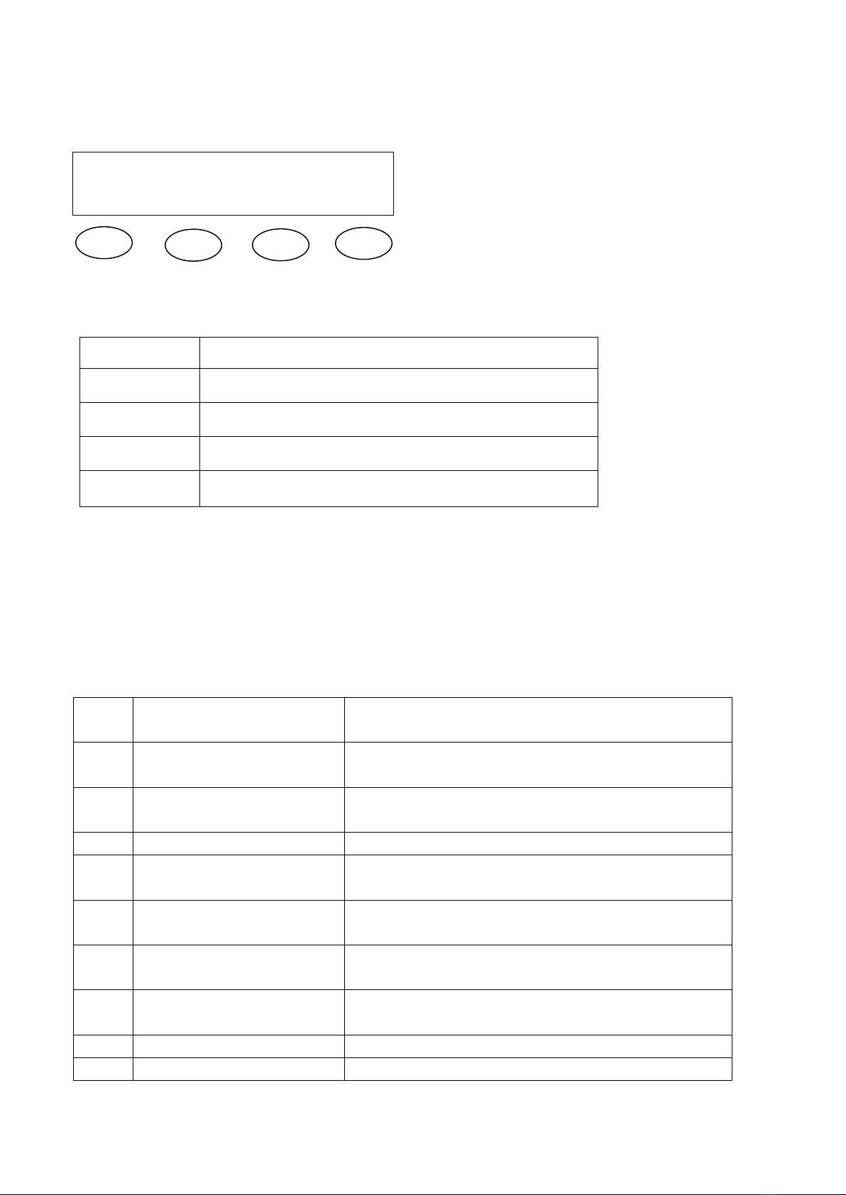
Data connect
Data cable is connected by DMX data wire, and XLR. Please use hi-quality data cable signal wire, it won’t be
interrupted by magnetic.
Characteristics of DMX data cable
2 conductors’ double tree lace and shield.
The maximum capacitance of the conductors-30 pF/ft.
The maximum capacitance of the conductor and shield -55 pF/ft.
The maximum resistance is 20 ohms/1000ft.
The nominal impedance 100-140 ohms.
DMX opt coupler segregate signal zoom equipment’s 3 pin(5 pin) XLR plug.
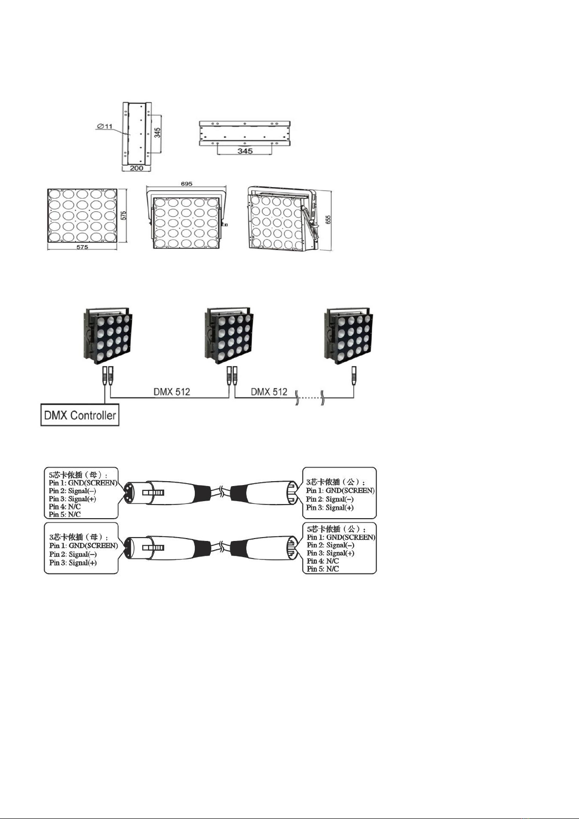
2.3 Setting up a DMX signal connect
As following pictures show, please connect the first light to the signal cable which is with XLR by DMX controller,
then, connect light in series.
The light must be set up the ventilating place. To confirm there is nothing to hinder the heat dissipation place.
When the light is hanged, please choose a safety wire.
3. Operating instructions
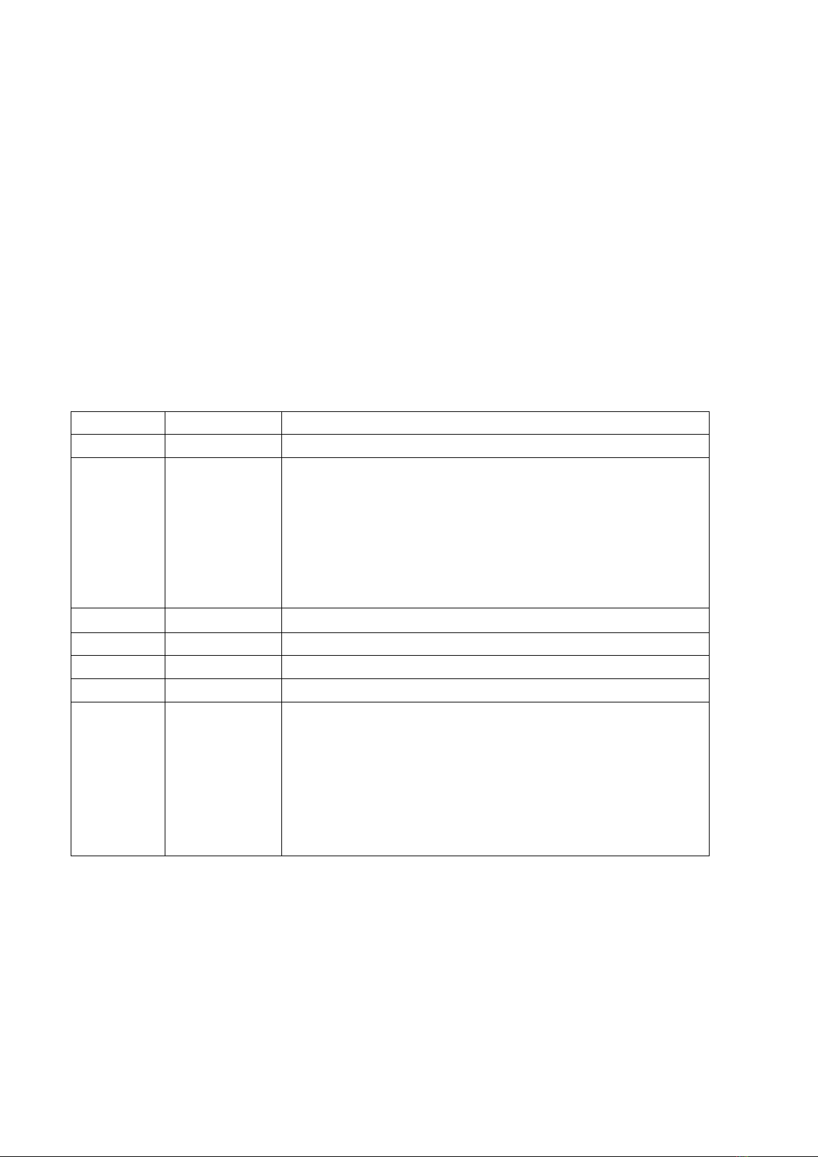
3.1 Menu configurations
Access control panel functions using the four panel buttons located directly under near the the LCD Display.
LCD display board
When a menu function is selected, the display will show immediately the first available option for the selected
menu function. To select a menu item, press<ENTER>.
Press the <MENU> button repeatedly until you reach the desired menu function. Use the <UP> and <DOWN>
buttons to navigate the menu options. Press the <ENTER> button to select the menu function currently displayed,
or to enable a menu option. To return to the previous option or menu without changing the value, press the
<MENU> button.
No alternative worth that return re-option or menu, press (MENU) button
3.2Menu function
1
A001
8 channels, address adjustable by B & C button
( 001--512)
2
H001
80 channels, address adjustable by B & C button
( 001--512)
3
CC00
Color change fast ,speed adjustable by B & C button
(01—99)
4
CP00
Gradual ,speed adjustable by B & C button (01—99)
5
DE00
Color gradually change ,speed adjustable by B & C button
(01—99)
6
FF00
Color jump to change ,speed adjustable by B & C button
(01—99)
7
BEB1
First Model: Sound activated Seven Colors Jumping to
Change
8
BEB2
Second Model: Sound activated Seven Colors Jumping to
Change
9
ID00
DMX512 ID, (00—51)
10
FROM
Slave, accept and control according to master’s signal
Button
Function
MENU
Used to access the menu or return to a previous menu
option.
DOWN
Scrolls through menu options in descending order.
UP
Scrolls through menu options in ascending order.
ENTER
Used to select and store the current menu or option within
a menu.
MENU
UP
DOWN
ENTER
3.3 User configurations
Set-up 1pcs light`s menu mode (Auto-running)
.Press the MENU, such as the picture 4.2 shows the menu function
.Use the UP/DOWN buttons to choose the right one to confirm.
Set-up Master-slave mode
Press the MENU, same as picture 4.2 shows the menu function
Master: Set any one of lights to auto、sound or strobe control mode
Slave: Set them to DMX mode and their address code to1.
Notes :Each Master-slave group can be one and only light in master, ensure lights under this group without
connection with any DMX controller.
Set-up
DMX mode
The light can connect to the DMX controller to receive its signal indication, which control by DMX controller. DMX
value is referenced by “
4.4 DMX channel values ”.
3.4 DMX channel values
8 channels
1
Dimmer
R、G、B Dimmer, Linear Dimmer, Dark to Bright
2
Strobe
R、G、B Strobe, Slow to Fast
3
Functions
0— 20 DMX 8Channel Controlling;
21—70: Color jumping to change;
71—120: Color gradually change;
121—170:color slowly change
171—220: dot running
221—240: Sound activation 1;
241--255:Sound activation 2
4
Function Speed
Function speed from slow to fast
5
R Dimmer
R, Linear Dimmer, Dark to Bright
6
G Dimmer
G, Linear Dimmer, Dark to Bright
7
B Dimmer
B, Linear Dimmer, Dark to Bright
8
DMX512 ID
ID 1 5--9
ID 2 10--14
ID 3 15--19
ID 4 20--24
........ .........
ID 51 255
If it is as same DMX Value, it can at most control 50 devices
80 channels
1
Dimmer
R、G、B Dimmer, Linear Dimmer, Dark to Bright
2
Strobe
R、G、B Strobe, Slow to Fast
3
Functions
1— 20 DMX 80Channel Controlling; 21—70: Color jumping to
change; 71—120: Color gradually change; 121—170:color
slowly change 171—220: dot running 221—240: Sound
activation 1; 241--255:Sound activation 2
4
Function Speed
Function speed from slow to fast
5
R1 Dimmer
R1, Linear Dimmer, Dark to Bright
6
G1 Dimmer
G1 Linear Dimmer, Dark to Bright
7
B1 Dimmer
B1 Linear Dimmer, Dark to Bright
8
R2 Dimmer
R2 Linear Dimmer, Dark to Bright
9
G2 Dimmer
G2 Linear Dimmer, Dark to Bright
10
B2 Dimmer
B2 Linear Dimmer, Dark to Bright
11
R3 Dimmer
R3 Linear Dimmer, Dark to Bright
…
…
…
80
DMX512 ID
ID 1 5--9
ID 2 10--14
ID 3 15--19
ID 4 20--24
........ .........
ID 51 255
If it is as same DMX Value, it can at most control 50 devices
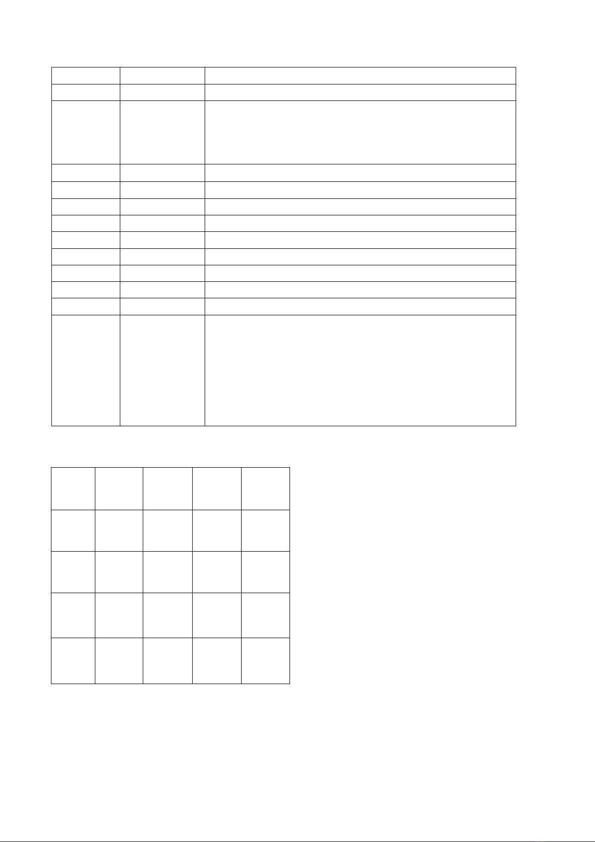
3.5 LED Rangement:
1
2
3
4
5
6
7
8
9
10
11
12
13
14
15
16
17
18
19
20
21
22
23
24
25
4. KEEPING THE PROJECTOR CLEAN
It denitely necessary to keep a projector clean for its reliable use. Cooling fans and their shield should
be cleaned every 15days. LED lamps’ lens and cover should be cleaned regularly for optimized light
output.
Cleaning frequency depends on how often a projector is used and its operational environment. A soft cloth
and typical glass cleaning products should be used in cleaning. It is recommended to clean the external
optics at least once every 20 days.
Do not use any organic solvent, e.g. alcohol, to clean t housing of the apparatus.
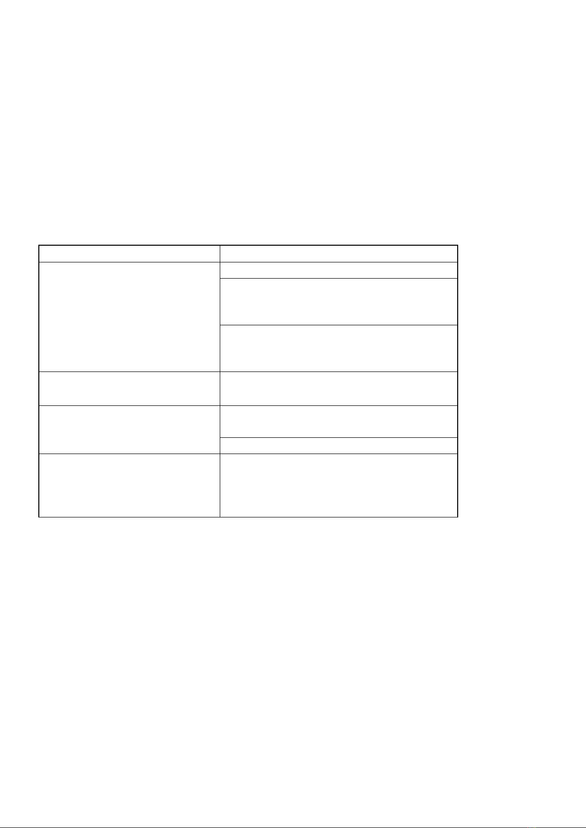
4.1 Troubleshooting
4.2 MAINTENANCE
To prolong a Projector’s life, Regular maintenance should be done for its LED optical System to ensure that the
system be in best operational condition. If the projector does not function, check the fuses on the power socket of
the projector, if burned, they should only be replaced by fuses of the same specication. Should these be damaged
call a qualied
PROBLEM
ACTION
The projector can’t be started
>Power Cable not connected well
>Power supply damaged or not
connected well, a qualied
Technician should be required
>Control board not connected well and a
qualied
Technician should be
The lamp can be started, but LED
Lamps are off and not controlled
>LED boards not connected
properly, a qualied technician is needed
A projector’s lamps are on but it
doesn’t respond to the controller
>Make sure that the projector’s start
address is correctly set
>Replace or repair the DMX cable.
The beam appears dim and
Its brightness slows sharply
>Ambient temperature too high
which result in a projector
overheating, necessary ventilating
measures needed.

5. Warrantee
One (1) Year Limited Warranty
Subject to the limitations set forth below, Nightowl Stage Lighting hereby represents and warrants that the
components of this product shall be free from defects in workmanship and materials, including implied
warranties of merchangeability or fitness for a particular purpose, subject to normal use and service, for one (1)
year the original owner from the date of purchase.
Retailer and manufacturer shall not be liable for damages based upon inconvenience, loss of use of product, loss
of time, interrupted operation or commercial loss or any other incidental or consequential damages including but
not limited to lost profits, downtime, goodwill, damage to or replacement of equipment and property, and any
costs of recovering, reprogramming, or reproducing any program or data stored in equipment that is used with
our products. This guarantee gives you specific legal rights. You may have other legal rights which vary from
country to state. Some country do not allow limitations on how long an implied warranty lasts, so the above
limitation may not apply to you.
6. Returns
Returned merchandise must be sent prepaid and in the original packing. Package must be clearly labeled with a
Return Merchandise Authorization Number (RMA #).
For repair and warrantee service contact contact DLG Stage Lighting for an RMA number and shipping instructions.
Include a phone number in case we need to speak to you in person. Our website contains all up to date contact
information.
7. Claims
Damage incurred in shipping is the responsibility of the shipper; therefore, the damage must be reported to the
carrier upon receipt of merchandise. It is the customer's responsibility to notify and submit claims with the shipper
in the event that a fixture is damaged due to shipping. Any other claim for items such as missing component/part,
damage not related to shipping, and concealed damage, must be made within seven (7) days of receiving
merchandise. We will be happy to assist you with your shipping claim should there be an issue.
Table of contents
Other Nightowl Stage Lighting Dj Equipment manuals


