NIKA NL-UHV / DX3 User manual

Nikalyte Ltd, 77 Heyford Park, Heyford Park Innovation Centre, Upper Heyford,
OX25 5HD, UK +44 (0)1869 238042. www.nikalyte.com 2
Contents
Safety Precautions ........................................................................................................ 3
Symbols:................................................................................................................... 3
Health and Safety –General Information ........................................................................ 3
Introduction ................................................................................................................. 4
Installation ................................................................................................................... 5
Operation..................................................................................................................... 5
NL-DX3 Sputter Head Targets..................................................................................... 5
Magnetron Target Installation..................................................................................... 6
Plasma Preventers .................................................................................................. 8
Start-up .................................................................................................................... 9
Striking a plasma ....................................................................................................... 9
Nanoparticle Generation ...............................................................................................10
Introduction .............................................................................................................10
Nanoparticle size variation.........................................................................................12
Indicative data .........................................................................................................13
Shut-down ...............................................................................................................16
Maintenance................................................................................................................16
Changing the Primary Orifice ..................................................................................19
Cleaning ..................................................................................................................19
Consumables ...............................................................................................................20
Troubleshooting...........................................................................................................20
Unable to strike a plasma ..........................................................................................20
The deposition rate is low or dropping........................................................................21
No Nanoparticles produced........................................................................................22
Source Materials .......................................................................................................23
Contacting us ..............................................................................................................23

Nikalyte Ltd, 77 Heyford Park, Heyford Park Innovation Centre, Upper Heyford,
OX25 5HD, UK +44 (0)1869 238042. www.nikalyte.com 3
Safety Precautions
Please read the following instructions carefully before installing the NL-DX3 and refer to them
as needed to ensure the continued safe operation.
Symbols:
= High Voltage
= Warning
= Information / Tip
Follow all warnings and instructions marked on or supplied with the product. Failure to
observe these precautions could lead to personal injury or death and/or damage to the
equipment.
Health and Safety –General Information
When connected to its power supply, the sputter source is supplied with potentially
lethal currents at very high voltages. The source should always be disconnected
from its supply during maintenance.

Nikalyte Ltd, 77 Heyford Park, Heyford Park Innovation Centre, Upper Heyford,
OX25 5HD, UK +44 (0)1869 238042. www.nikalyte.com 4
The toxicity of nanoparticles has not been determined in many cases and
consequently care should be taken when opening the vacuum system. Always use
gloves and the use of a fine-filter mask is also highly recommended as an absolute minimum.
Please note that some materials will burn if you use an IPA wipe for cleaning. Such
materials are Platinum, Hafnium and Iron. For cleaning systems which contain
these materials, use lint free wipes with a few drops of DI water and immediately drop the
used wipes into a bucket of water. This will render the materials safe.
Introduction
The NL-UHV nanoparticle source consists of a UHV compatible vacuum envelope which houses
a range of sputter sources specifically designed to work together to generate nanoparticles of
many types of materials.
The sources that are compatible with the NL-UHV include a single 1” source (NL-D1), a single
2” source (NL-D2), a single 3” source (NL-D3) and a triple 1” source (NL-DX3). This manual
covers the operation of the NL-UHV in combination with the NL-DX3.
Each individual sputter source is known as and will be referred to here as a
magnetron
.
Extreme caution is required when working with the magnetron power supplies. Do
not switch them on unless all leads are connected and shielded. All supplies, cables
and equipment must be suitably earthed.
Nanoparticles are formed when the magnetron(s) are running and sputtering material under
a range of conditions. The user can control several parameters to control the formation and
size of the nanoparticles. These parameters include gas flow (usually argon) over the
magnetron(s), a separate ‘carrier’ gas flow (usually helium), plasma power, magnetron to

Nikalyte Ltd, 77 Heyford Park, Heyford Park Innovation Centre, Upper Heyford,
OX25 5HD, UK +44 (0)1869 238042. www.nikalyte.com 5
aperture distance, and aperture size. The magnetron(s) are typically powered by 630V, dc
supplies, but in addition pulsed DC supplies can be used.
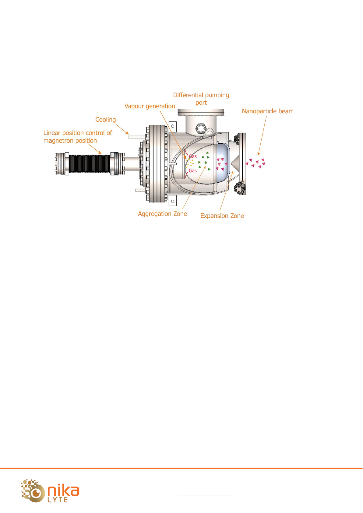
The NL-UHV produces nanoparticles by two main processes; 1) generation of atomic and
molecular species by magnetron sputtering and 2) subsequent generation of nanoparticles by
condensation in an aggregation zone. The NL-UHV consists of two zones, the Aggregation
zone and the Expansion zone with apertures between. The Expansion zone is differentially
pumped by a 300 l/s turbo pump.
Installation
For detailed information on the installation and the services required, please see the
accompanying document NL-Dxx & NL- QMS Installation.
Operation
NL-DX3 Sputter Head Targets

Nikalyte Ltd, 77 Heyford Park, Heyford Park Innovation Centre, Upper Heyford,
OX25 5HD, UK +44 (0)1869 238042. www.nikalyte.com 6
The toxicity of nanoparticles has not been determined in many cases, consequently care
should be taken when removing the NL-DX3 after use. Always use gloves. The use
of a fine-filter mask is also highly recommended. Use a fume hood if you have one.
Nanoparticles can be highly reactive. When venting a chamber for the first time
after extended use, rapid oxidation of the nanoparticles may lead to strong
exothermic heating. Take particular care when cleaning the aggregation zone.
Nanoparticle residues removed with flammable material (paper tissue for example) may heat
up and spontaneously combust.
Magnetron Target Installation
In order to fit a source target, it is necessary to remove the NL-DX3 from the NL-UHV chamber.
The NL-UHV chamber can remain connected to the main system chamber if desired.
Use the following procedure:
1. Isolate the magnetron power supplies.
2. Vent the vacuum system.
3. Disconnect the water-cooling connections to the NL-DX3.It is a good idea to cap the
water tubes on the source to prevent spillage.
4. Disconnect the magnetron power supply cables. The source has three magnetron
heads, it is important to make sure you note which wires go to which source. The
source feedthroughs are etched 1, 2 and 3.
5. Disconnect the gas connections to the source, note the orientation of the two
connections.
6. Remove the 16 cap head bolts connecting the source to the NL-UHV chamber.

Nikalyte Ltd, 77 Heyford Park, Heyford Park Innovation Centre, Upper Heyford,
OX25 5HD, UK +44 (0)1869 238042. www.nikalyte.com 7
7. Carefully remove the source from the chamber.
8. The source has 3 targets, each secured
independently via its own target ring.
To access the targets, it is easiest to
remove the Anode Cap first. Note the
orientation of the anode cap to the
assembly,
9. Loosen by about 3 turns, but don’t
remove the three Target Ring securing
screws from the head.
10. Rotate the target ring and remove it.
11. The new target will be clamped to the
top surface of the source (actually
called the cathode) by the target ring.
12. Make sure that the surface of the
cathode and the target is free from
dust, chips and has a smooth finish.
13. When refitting / replacing the target, make sure that the mating surface of the source
(known as the cathode) is clean and that there is no material on it that will prevent
the new target making a good thermal contact with the cathode. Good cooling of the
rear of the target face is very important.
14. Fit the target and replace the target ring, rotate the ring back into position and tighten
the three securing screws slowly and evenly to ensure that the target is evenly
clamped to the source.
15. Clean and refit the Anode cap to the assembly in the original orientation, referring to
the indicators on the side of the Lower Anode and Anode Cap. The Anode Cap has
been etched to identify which number magnetron pocket is which.
16. With a multimeter, check that each target is isolated from ground and the anode, and
makes contact to the relevant source vacuum feedthrough.
17. Fit a new CF100 copper gasket to the NL-UHV chamber flange.

Nikalyte Ltd, 77 Heyford Park, Heyford Park Innovation Centre, Upper Heyford,
OX25 5HD, UK +44 (0)1869 238042. www.nikalyte.com 8
18. Re-mount the source to the NL-UHV chamber
and tighten the 16 cap head bolts evenly.
19. Using a multimeter, double check that each
magnetron feedthrough is isolated from
ground.
20. Reconnect the gas connections to the source,
using new ¼” VCR gaskets.
21. Reconnect the power connections.
22. Reconnect the water pipes in the original
positions, note the connections should be as
shown.
Plasma Preventers
Plasma preventers are thin rings which fit between the target
ring and top of the cathode. They surround the target itself.
The purpose of the Plasma Preventers is to reduce the gap that
would exist between the outside of the target and the anode.
A gap in this position would cause a plasma to form in that area
which could cause etching of the surrounding surfaces.
There should be a small gap between the Plasma Preventers
and the target ring, so that the rings are free to “float” when
the target ring is clamping the target down to the cathode.
When using a 3mm thick target, two Plasma Preventer rings
should be used which reduces the gap to less than 0.5mm when
the target is fitted. If thinner targets used then the number of
plasma preventer can be reduced.

Nikalyte Ltd, 77 Heyford Park, Heyford Park Innovation Centre, Upper Heyford,
OX25 5HD, UK +44 (0)1869 238042. www.nikalyte.com 9
Start-up
Before start-up ensure that:
The Power cable(s) is (are) attached to the source.
All power supplies and the chamber are suitably earthed.
Water cooling is flowing at a minimum of 1.5 l/min to the sputter head. Lack of
water cooling to the sputter head may cause overheating and damage.
It is advisable to interlock the power supplies such that if the water and / or
vacuum fails, the supplies are disabled so no damage can be caused to the
magnetrons.
Suitable gases are connected, the gases are pure and the gas lines have been
purged.
The vacuum chamber has pumped down to a pressure of at least 1 x 10⁻⁵ mbar,
though a pressure of 1 x 10⁻⁶ mbar or better is preferable. The differential turbo
and backing pump should be run at the same time as the deposition chamber
pump.
Striking a plasma
The magnetron plasma is started by introducing gas into the source and switching on the DC
power supply.
Introduce Argon gas flow. Typically, 10 sccm of Argon is sufficient. When working with a new
target, or after the system has been vented, it is useful to reduce the gas flow after a plasma
has been struck to a value of 2 or 3 sccm for a period of 10 minutes to half an hour to allow
the target to “clean up” and the plasma voltage to settle to a stable value. This is essential
for targets that tend to oxidise quickly, for example titanium and aluminium targets.
The lower limit of gas flow required to maintain a stable plasma will be to some extent target
dependent but for most target materials a value of 2 to 3 sccm should be sufficient.

Nikalyte Ltd, 77 Heyford Park, Heyford Park Innovation Centre, Upper Heyford,
OX25 5HD, UK +44 (0)1869 238042. www.nikalyte.com 10
Switch on the high voltage supply. Before enabling the high voltage set the maximum output
voltage to 630V (following the manufacturer’s instructions for the supply) and the output
current to 100mA using the preview function on the front panel of the DC supply (if the supply
is equipped with a preview facility).
Once the HV and current values have been set, enable the high voltage. If the target is new
or the system has been vented to air there will be a period of arcing before a stable plasma
is achieved. Once the plasma has been struck (as evidenced by a stable current reading) the
voltage will normally trend downwards (or sometimes upwards and then downwards whilst
the target surface is cleaned) before stabilising at a given current and gas flow. After the
plasma has struck the power of the sputtering process can be controlled by varying the
current.
Care must be taken not to sputter through the target material as this will cause
damage to the sputter head. When developing a new process or working with a
new target material regular inspection of the target should be made to monitor
target usage. The operating voltage will drop continuously over the lifetime of a target and
so can be a useful way to monitor the target usage.
Some target materials (such as ITO) are very brittle and can crack due to rapid
changes in temperature. In such cases ramp the power up and down slowly to
prevent rapid temperature changes. It can also be helpful to use a thin copper backing plate
between the cathode and the target to reduce the thermal stress.
Nanoparticle Generation
Introduction
The operation of the NL-DX3 is straightforward and it is relatively simple to generate a
nanoparticle beam. However, the formation of nanoparticles is a complex process which
depends on gas flow, pressure, material properties, density and plasma conditions. As a
consequence, it is difficult to recommend an absolute set of parameter values which will lead
to predictable nanoparticle properties for each material type, although broad guidelines will
generally hold true.

Nikalyte Ltd, 77 Heyford Park, Heyford Park Innovation Centre, Upper Heyford,
OX25 5HD, UK +44 (0)1869 238042. www.nikalyte.com 11
Here are some practical tips which will help the user become accustomed to the parameters
which influence the formation of the nanoparticles.
The source consists of three DC magnetron heads which are enclosed within a high-pressure
Aggregation zone and a differentially pumped Expansion zone. The parameters and conditions
which control the formation and size of the nanoparticles are described below. Together with
experimental data these should act as a starting point to the user.
Each individual target should be cleaned using the low argon flow plasma (as described above)
to ensure a clean, pure surface to generate nanoparticles. This process should be repeated
when switching from one magnetron head to another to remove any cross-contaminated
sputtered material from the adjacent sources.
It is beneficial to be able to measure the nanoparticle flux, or deposition rate produced by the
NL-UHV. The most practical way to do this is to use a quartz crystal monitor (QCM) as is
common practice for sputter deposition. It is ideal to place the QCM at a distance of around
150mm from the exit aperture. Copper is an ideal material to use to characterise the source.
The NL-DX3 should be able to produce a measured deposition rate of 0.1 - 1 Angstrom per
second dependent upon the target material, distance and position in relation to the particle
beam.
It is important to note that below a critical flow value of argon there may be no
nanoparticle flux generated!
Once a deposition rate has been measured by the QCM it is useful to change some of the
parameters to see how they affect the deposition rate. If a Nikalyte NL-QMS has been placed
in line then the nanoparticle size distribution may also be measured and selected.
Note that the beam from the front of the NL-QMS is collimated at around 40mm
diameter, so the QMS should be located in the beam during measurement.

Nikalyte Ltd, 77 Heyford Park, Heyford Park Innovation Centre, Upper Heyford,
OX25 5HD, UK +44 (0)1869 238042. www.nikalyte.com 12
Nanoparticle size variation
A number of parameters can be varied to alter the size of the nanoparticles. In general, to
achieve large shifts in mean nanoparticle size, two or more parameters should be varied
together. As a general rule, for very small particles, use
low
power,
low
Ar flow,
high
He flow
and
high
aggregation length.
However, the effect of these parameters on the nanoparticle size distribution depends very
strongly on the nucleation temperature (the optimum temperature for nanoparticle formation)
of the material.
This figure shows the approximate relationship
between the various parameters and particle
size.
Ar is the discharge gas. Increasing Ar pressure
allows more rapid thermalisation and hence
more rapid particle formation but will also
sweep the particles through the aggregation
zone more rapidly thus reducing the time for
particle growth.
He is a carrier gas which sweeps the particles
out of the aggregation zone.
Power changes the density of the target
vapour and hence the particle size.
Aggregation length changes the time the
particles spend in the aggregation zone and
hence the size.
Since the NL-DX3 has three sources which can
be run independently in terms of power, but share common gas supplies there will always be
some interplay between the sources. In addition, some materials behave differently to others.
This can cause particle size to not follow these trends. You are encouraged to explore a wide
parameter space to find the optimum conditions for your process.

Nikalyte Ltd, 77 Heyford Park, Heyford Park Innovation Centre, Upper Heyford,
OX25 5HD, UK +44 (0)1869 238042. www.nikalyte.com 13
Indicative data
The NL-DX3 enables the user to sputter 3 different materials together and explore the
formation of binary, ternary and hybrid nanoparticle structures. By varying the power to each
magnetron, the user can explore different compound or alloy compositions.
The plot below shows typical mass distribution spectra for Ti, Ag and Cu deposited together
using the NL-DX3. The data was collected using the inline NL-QMS mass filter. In the plot the
gas flow (PAr), aggregation length (Lg) and the current to the Ag (IAg)and Ti (ITi) magnetrons
are fixed.
The data shows the change in the mass distribution as the current to the copper magnetron
(I_Cu) is increased. The strongest signal is observed for currents of 50mA for copper, 80mA
for silver and 250mA for titanium. The peak position is also affected by the changing currents
to the individual sputter sources. Note that for the case of alloy nanoparticle deposition the
QMS size distribution is plotted as mass rather than diameter, as the true mass of the
nanoparticles generated is dependent on the alloy fractions and is not yet known.

Nikalyte Ltd, 77 Heyford Park, Heyford Park Innovation Centre, Upper Heyford,
OX25 5HD, UK +44 (0)1869 238042. www.nikalyte.com 14
The plots below show examples of nanoparticle distributions of copper for varying process
parameters of Argon gas flow, magnetron current and aggregation length. The data was
collected by placing the Nikalyte NL-QMS mass filter in line with the NL-DX3. In all three plots
the peak position, distribution width and the peak intensity vary with gas flow, aggregation
length and current. Thus, the peak size, range of sizes and the number of nanoparticles
generated can be varied by changing the process parameters.
When comparing the real data with predicted trends, see section Nanoparticle size variation,
it is clear that the real data follows some but not all the general trends. This is normal and
reflects the complex interplay of thermodynamics, kinetics and surface chemistry that occurs
inside the aggregation zone.
You are encouraged to explore parameter space for their specific materials and use the
predicted trends as a starting point. Knowledge of the sputtering parameters of the material
is also useful to note, as heavy materials such as gold and platinum with high sputter yields
provide higher nanoparticle deposition rates than lower density materials such as aluminium.
Another important parameter to understand is the nucleation temperature of the material,
which is the plasma temperature at which the materials readily form nanoparticles. This
temperature may be calculated, and you can also experiment with varying the plasma
temperature by using different power supplies such as pulsed dc, adding helium gas or using
different coolants, such as LN2 in the aggregation zone cooling jacket.
Do not use LN2 in the NL-DX3 Source, or damage to the source will result!
The NL-UHV has an additional level of flexibility which is the ability to change the diameter of
the orifice in the front of the aggregation zone. This will affect the environment in the
aggregation zone in terms of pressure, gas flow and dynamics, and hence nanoparticle size
etc. See the section Changing the Primary Orifice. The orifice that is fitted as standard is
3mm diameter. The installation pack includes orifices of 2, 4 and 5mm diameter.

Nikalyte Ltd, 77 Heyford Park, Heyford Park Innovation Centre, Upper Heyford,
OX25 5HD, UK +44 (0)1869 238042. www.nikalyte.com 16
Shut-down
The source is switched off by either reducing the gas flow, or the output on the DC power
supply. The source may be quickly re-started by the reverse of this process. Care should be
taken if you have been using a fragile target material to reduce the magnetron power slowly
to avoid thermal shock which may fracture a delicate target.
Maintenance
The NL-DX3 source is designed to require little maintenance. The main areas which require
periodic maintenance and inspection are the target mounting areas of the source. As the
source is used, the deposited material will build up around the target, the target ring and
around the surrounding anode.
The toxicity of nanoparticles has not been determined in many cases, consequently care
should be taken when removing the NL-DX3 after use. Always use gloves. The use
of a fine-filter mask is also highly recommended. Use a fume hood if you have one.
Nanoparticles can be highly reactive. When venting a chamber for the first time
after extended use, rapid oxidation of the nanoparticles may lead to strong
exothermic heating. Take particular care when cleaning the aggregation zone.
Nanoparticle residues removed with flammable material (paper tissue for example) may heat
up and spontaneously combust.
Use the following procedure to clean the source head:
1. Isolate the magnetron power supplies.
2. Vent the vacuum system.
3. Disconnect the water-cooling connections to the NL-DX3. It is a good idea to cap the
water tubes on the source to prevent spillage.
4. Disconnect the magnetron power supply cables. The source has three magnetron
heads, it is important to make sure you note which wires go to which source. The
Source feedthroughs are etched 1, 2 and 3.

Nikalyte Ltd, 77 Heyford Park, Heyford Park Innovation Centre, Upper Heyford,
OX25 5HD, UK +44 (0)1869 238042. www.nikalyte.com 17
5. Disconnect the gas connections to the source, note the orientation of the two
connections.
6. Remove the 16 cap head bolts connecting the source to the NL-UHV Chamber.
7. Carefully remove the source from the chamber.
8. The source has 3 targets, each secured independently via its own target ring. To
access the targets, it is easiest to remove the Anode Cap first. Note the orientation of
the anode cap to the assembly.
9. Loosen by about 3 turns, but don’t remove the three Target Ring securing screws from
the target you are changing.
10. Rotate the target ring and remove it.
11. The target should then come free
from the source below. It may need a
light tap to allow it to float free.
12. When replacing the target material
with a different material it is good
practice to clean the target ring and
the anode cap before replacement.
13. After prolonged use it will be
necessary to remove and clean the
Lower Anode, which is achieved by
removing the three long cap head
screws on the top of the lower anode.
14. It is MOST IMPORTANT to ensure
that the lower cathode and anode cap
are replaced in the original orientation, there are alignment arrows on the both parts
to make this easy. Please refer to the diagram below.
15. When refitting / replacing the target, make sure that the mating surface of the source
(known as the cathode) is clean and that there is no material on it that will prevent
the new target making a good thermal contact with the cathode. Good cooling of the
rear of the target face is very important.

Nikalyte Ltd, 77 Heyford Park, Heyford Park Innovation Centre, Upper Heyford,
OX25 5HD, UK +44 (0)1869 238042. www.nikalyte.com 18
16. Refit the target and replace the target ring, rotate the ring back into position and
tighten the three securing screws slowly and evenly to ensure that the target is
evenly clamped to the source.
17. Clean and refit the Anode cap to the assembly in the original orientation, referring to
the indicators on the side of the Lower Anode and Anode cap. The Anode cap has
been etched to identify which number magnetron pocket is which.
18. With a multimeter, check that each target is isolated from ground and makes contact
to the relevant source vacuum feedthrough.
19. Fit a new CF100 copper gasket to the NL-UHV chamber flange.
20. Re-mount the source to the NL-UHV chamber and
tighten the 16 cap head bolts evenly.
21. Using a multimeter, double check that each
magnetron feedthrough is isolated from ground.
22. Reconnect the gas connections to the source,
using new ¼” VCR gaskets.
23. Reconnect the power connections.
24. Reconnect the water pipes in the original
positions, note the connections should be as
shown.

Nikalyte Ltd, 77 Heyford Park, Heyford Park Innovation Centre, Upper Heyford,
OX25 5HD, UK +44 (0)1869 238042. www.nikalyte.com 19
Changing the Primary Orifice
To change the Primary Orifice:
1. Remove the source from the NL-UHV chamber as detailed in the section Magnetron
Target Installation.
2. The Primary Orifice is then visible at the far end of the aggregation zone.
3. Clean the aggregation zone internally with reference to the warnings in the section
Cleaning.
4. Using a long Pozidrive screwdriver, remove the orifice securing screws being careful
not to drop the screws into the hole in the orifice or into the zone below the
aggregation zone.
5. The orifice will now be removable.
6. When installing the replacement orifice, again be very careful not to drop the screws.
7. Do not overtighten the securing screws.
Cleaning
The toxicity of nanoparticles has not been determined in many cases and
consequently care should be taken when removing the source after use. Always
use gloves and the use of a fine-filter mask is also highly recommended.

Nikalyte Ltd, 77 Heyford Park, Heyford Park Innovation Centre, Upper Heyford,
OX25 5HD, UK +44 (0)1869 238042. www.nikalyte.com 20
NOTE: Some nanoparticle deposits can be highly reactive. Avoid using volatile
solvents when removing the initial deposits as these can spontaneously combust.
The NL-DX3 Anode cap may require periodic cleaning from material build-up. Mostly the
material will not be strongly adherent and can be removed by wiping or gentle abrasion. It is
not necessary to regularly clean the inside of the aggregation unless there is a build-up of
flakes obscuring the apertures or you are experiencing difficulties generating or maintaining
a deposition rate of nanoparticles (see troubleshooting section). A well coated aggregation
zone is often helpful for nanoparticle formation. However if you do decide to clean the
aggregation zone the material inside will normally be powdered and can be readily removed
with a wipe Periodic visual checks to ensure the apertures are free of flakes is advised.
Sputtered material, i.e., material that has not formed nanoparticles can be harder to remove.
To remove this an abrasive pad or Dremel is often used. We do not recommend doing this
unless necessary to avoid masking or if the sputtered material is causing short circuits.
Consumables
The only consumables required in the NL-DX3 range are the sputter targets. The condition of
the targets should be inspected on a regular basis to avoid sputter damage to the cathode in
the event of the target being fully used. Typically, a sputter target will last up to 10 hours at
a sputter current of around 200mA (although this is dependent on the target material,
thickness of the target etc). After a while the user will be able to determine optimum sputter
rates for their particular process.
Troubleshooting
Unable to strike a plasma
Note that a fresh target may arc for a period lasting up to a minute as it cleans up. This is
quite normal.
Arcing can last longer than this for very old targets which have a thick oxide. In this case it is
worth persevering with cleaning at low gas flow for up to 10mins.
Table of contents