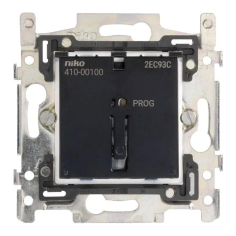
Niko 05-002-02 User manual

nv Niko sa Industriepark West 40, BE-9100 Sint-Niklaas, Belgium — tel. +32 3 778 90 00 — fax +32 3 777 71 20 — e-mail: [email protected] — www.niko.be PM005-00202R15342
05-002-02
Lees de volledige handleiding vóór installatie en ingebruikname.
1. BESCHRIJVING
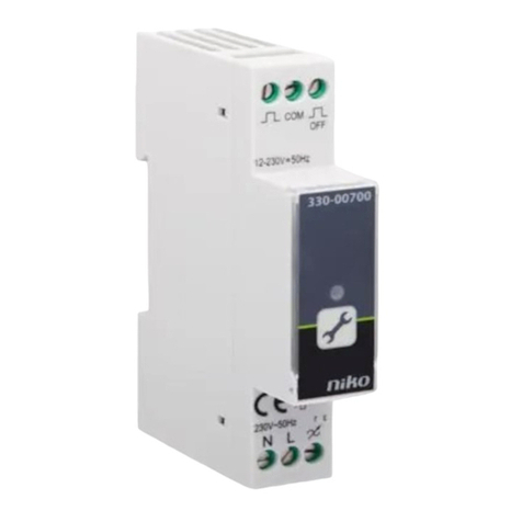
De schakelmodule schakelt en stuurt wandcontactdozen en elektrische verbruikers via contactoren. De module
dimt via modulaire Niko-dimmers. De schakelmodule werkt zowel centraal als decentraal (fig. 1 & 2) en past in
elke modulaire verdeelkast (4E breed). De schakelmodule heeft een galvanisch gescheiden voeding voor eigen
gebruik, een specifieke uitgang voor de busleiding, een detectiecircuit, diagnosefuncties, een onverliesbaar
geheugen, insteltoetsen, een microprocessor, een LED-interface, een relais en indicatoren voor alle functies.
De schakelmodule beschikt over 4 gescheiden circuits met enkelpoligerelaisuitgangscontacten.Als meer uitgangen
vereist zijn, kan u verschillende modules parallel schakelen. Hou hierbij wel rekening met de polariteit van de bus.
Verbind uitgang B1 van de ene module met uitgang B1 van de andere module. Eén van de modules neemt de
voeding voor de bus op zich, de andere schakelen automatisch de voeding uit. U kan de verschillende functies
van de busdrukknoppen met de mode-toets instellen. Na een netonderbreking worden de uitgangen met enig
tijdsverschil terug aangezet om een stroompiek te vermijden. Het geheugen is onverliesbaar, bij spanningsuitval
is geen batterij vereist. Het geheugen is steeds herprogrammeerbaar zonder de module te openen (EEPROM).
2. BIJZONDERHEDEN
Inbedrijfstellingsfunctie
Druk kort op de select-toets om de uitgangen manueel te selecteren. Druk lang (>1s.) om de uitgang tijdelijk
aan te zetten:
• als de bus nog niet geïnstalleerd is
• om de uitgangen te bedienen bij defect op de bus (kortsluiting of onderbreking)
• om uitgangscircuits te testen of te lokaliseren.
Diagnoserapportering
Bijnormalewerking(niettijdensprogrammering)iser een permanente diagnoserapportering ophet7-segmentdisplay:
• een horizontaal streepje licht op bij ontvangst van een juist Nikobus-telegram
• een grote A knippert in geval van kortsluiting of polarisatiefouten (bv. verwisseling van de buspolariteit tussen
2 modules)
• een kleine b knippert in geval van fouten van de busvoeding (circuit defect)
• een grote C knippert in geval van een geheugencommunicatiefout (bv. EEPROM-defect) of in geval van gebruik
van een verkeerd type module (bv. geheugen van een rolluikmodule in een dimcontroller).
Centrale functies met bedieningstijd (1 tot 3s., bij mode M2 en M3)
De bedieningstijd kan ingesteld worden tussen 1s. en 3s. Een eerste toepassing kan bv. om veiligheidsredenen
zijn:druk 2s. op een toets om alle lichten uit te schakelen.Een andere toepassing: op 1 toets worden verschillende
acties vastgelegd in functie van de bedieningstijd.
Stappenschakelaar (mode M13)
Voornamelijk geschikt als de belasting verdeeld moet worden door gebrek aan debiet,bv.bij watersproeisystemen
voor gazon, bloem- of groentenkwekerij, bestuurbaar verluchtingssysteem. Eveneens geschikt om het licht in
ruimtes met lichtgevoelige planten in opeenvolgende stappen te schakelen. Zo wordt het algemeen lichtniveau
niet te veel opgedreven en vermindert de impact op de sfeerverlichting.
Sferen (mode M14 en M15)
Om sferen te creëren kan u een bepaald aantal uitgangen (bv. lampen) naar eigen keuze aan- of uitschakelen.
Druk lang op de sfeertoets om de sfeer vast te leggen. Druk kort op de sfeertoets om de sfeer terug op te roepen.
U kan een sfeer altijd wijzigen door een nieuwe sfeer in te stellen en op te slaan. Druk lang op de sfeertoets om
de vorige sfeer te overschrijven. Elke busdrukknop mag als sfeertoets bepaald worden.
Met M14 kan een sfeer enkel ingeschakeld worden, elke uitgang wordt daarna individueel geschakeld.
Met M15 kan een sfeer volledig aan- of uitgeschakeld worden.
TECHNISCHE GEGEVENS
Omgevingstemperatuur: 0° tot 50°C
Voeding schakelmodule: 230V/5W
2 klemmen: per klem max. 4 x 1,5mm2of 2 x 2,5mm2
Netaansluiting: 230V/10A
2 klemmen: per klem max. 4 x 1,5mm2of 2 x 2,5mm2
Uitgangen: 230V/10A, 4 N.O.
per klem max. 4 x 1,5mm2of 2 x 2,5mm2
Busaansluiting: 9V DC (ZLVS, zeer lage veiligheidsspanning)
2 klemmen: per klem max. 2 x 1,5mm2
Onverliesbaar EEPROM-geheugen (2Kbyte)
Afmetingen (H x B x D): DIN-behuizing 4 modules breed: 88mm x 69mm x 60mm
3. WAARSCHUWINGEN VOOR INSTALLATIE
• De installatie moet worden uitgevoerd door een erkend installateur en volgens de geldende voorschriften.
•
Deze handleiding moet aan de gebruiker worden overhandigd. Het moet bij het dossier van de elektrische
installatie worden gevoegd en worden overgedragen aan eventuele nieuwe eigenaars. Bijkomende exemplaren zijn
verkrijgbaar via de website of supportdienst van Niko. Op de Niko website is altijd de meest recente handleiding
van het product terug te vinden.
• Tijdens de installatie moet rekening gehouden worden met (niet-limitatieve lijst):
- de geldende wetten, normen en reglementen.
- de stand van de techniek op het moment van de installatie.
- deze handleiding die alleen algemene bepalingen vermeldt en moet worden gelezen in het kader van elke
specifieke installatie.
- de regels van goed vakmanschap.
Dit product voldoet aan alle toepasselijke Europese richtlijnen en verordeningen. Indien van toepassing, vind je
de EG-verklaring van overeenstemming met betrekking tot dit product op www.niko.eu.
4. NIKO SUPPORT
Heb je twijfel? Of wil je het product omruilen in geval van een eventueel defect? Neem dan contact op met je
groothandel of de Niko supportdienst:
België: +32 3 778 90 80
Nederland: +31 183 64 06 60
Contactgegevens en meer informatie vind je op www.niko.eu onder de rubriek “Hulp en advies”.
5. GARANTIEBEPALINGEN
• De garantietermijn bedraagt vier jaar vanaf leveringsdatum. Als leveringsdatum geldt de factuurdatum van
aankoop van het product door de consument. Als er geen factuur voorhanden is, geldt de productiedatum.
• De consument is verplicht Niko schriftelijk te informeren over het gebrek aan overeenstemming, en dit uiterlijk
binnen de twee maanden na vaststelling.
• In geval van een gebrek aan overeenstemming heeft de consument enkel recht op een kosteloze herstelling
of vervanging van het product, wat door Niko bepaald wordt.
• Niko is niet verantwoordelijk voor een defect of schade als gevolg van een foutieve installatie, oneigenlijk of
onachtzaam gebruik, een verkeerde bediening, transformatie van het product, onderhoud in strijd met de
onderhoudsvoorschriften of een externe oorzaak zoals vochtschade of schade door overspanning.
• De dwingende bepalingen in de nationale wetgeving over de verkoop van consumptiegoederen en de bescherming
van consumenten in landenwaar Niko rechtstreeksof via zuster- ofdochtervennootschappen, filialen, distributeurs,
agenten of vaste vertegenwoordigers verkoopt, hebben voorrang op bovenstaande bepalingen.
Dit product mag u niet bij het ongesorteerd afval gooien. Breng uw afgedankt product naar een containerpark of een
erkend verzamelpunt. Net als producenten en importeurs speelt ook u een belangrijke rol in de bevordering van sortering,
recycling en hergebruik van afgedankte elektrische en elektronische apparatuur.Om de ophaling en verwerking te kunnen
financieren, heft de overheid in bepaalde gevallen een recyclingbijdrage (inbegrepen in de aankoopprijs van dit product).
Mode Functie Omschrijving Aantal bedieningsknoppen
De modes M1 tot M8 worden opgeroepen door de ”mode”-toets tijdens het programmeren minder dan 1,6s. in te drukken. De programmeermodes worden weergegeven op het 7-segmentdisplay.
M1:........aan/uit.............................................................................................boven: aan, onder: uit ................................................................................................................................................................. 2
M2:........aan (eventueel met bedieningstijd) ...................................................steeds aan (centrale functies)......................................................................................................................................................1
M3:........uit (eventueel met bedieningstijd) ..................................................... steeds uit (centrale functies) .......................................................................................................................................................1
M4:........drukknop.........................................................................................aan zolang er geduwd wordt (bv.. beldrukknop, dimmeraansturing) max.8s. ................................................................................1
M5:........impuls .............................................................................................puls aan/puls uit (bv.. impulsschakelaar of teleruptor)..................................................................................................................1
M6:........vertraagd afvallend (langere tijden, tot 2u)........................................ drukken: aan, na verloop van bepaalde tijd: uit (bv. trapautomaat)................................................................................................1
M7:........vertraagd opkomend (langere tijden, tot 2u)......................................drukken: na verloop van bepaalde tijd: aan (bv. actievertraging) ...................................................................................................1
M8:........knipperen ........................................................................................drukken: aan/uit/aan/..., uitschakelen: M3 ..................................................................................................................................1
De modes M11 tot M15 worden opgeroepen door de ”mode”-toets tijdens het programmeren langer dan 1,6s. in te drukken. De programmeermodes worden weergegeven op het 7-segmentdisplay.
M11: ......vertraagd afvallend (kortere tijden, tot 50s.) .....................................zoals M6, maar kortere tijden......................................................................................................................................................1
M12:......vertraagd opkomend (kortere tijden, tot 50s.)...................................zoals M7, maar kortere tijden ...................................................................................................................................................... 1
M13:......stappenschakelaar aan/uit...............................................................na elkaar schakelen van meerdere uitgangen via een tijdcyclus....................................................................................................2
Vrij te kiezen volgorde bij het programmeren bepaalt de uiteindelijke schakelvolgorde.
M14:......sfeer aan ......................................................................................... kort drukken: oproepen van een bepaalde sfeer...........................................................................................................................1
lang drukken: schrijft de gewijzigde sfeer in het geheugen (> 3s.)
M15:......sfeer aan/uit ....................................................................................bovenste toets kort drukken: oproepen van een bepaalde sfeer....................................................................................................2
bovenste toets lang drukken: schrijft de gewijzigde sfeer in het geheugen (> 3s.)
onderste toets —> uit
M16, 17, 18 hebben voorlopig geen functie
Tijden bij modes M6, M7 en M13: Tijden bij modes M11 en M12 (korte tijden): Tijden bij modes M2 en M3 (bedieningstijd):
0 = 10s. 0 = 0,5s. 0 = 0s.
1 = 1min. 6 = 6min. B = 30min. 1 = 1s. 6 = 6s. B = 20s. 1 = 1s.
2 = 2min. 7 = 7min. C = 45min. 2 = 2s. 7 = 7s. C = 25s. 2 = 2s.
3 = 3min. 8 = 8min. D = 60min. 3 = 3s. 8 = 8s. D = 30s. 3 = 3s.
4 = 4min. 9 = 9min. E = 90min. 4 = 4s. 9 = 9s. E = 40s. 4,...,F = 0s.
5 = 5min. A = 15min. F = 120min. 5 = 5s. A = 15s. F = 50s.

nv Niko sa Industriepark West 40, BE-9100 Sint-Niklaas, Belgium — tel. +32 3 778 90 00 — fax +32 3 777 71 20 — e-mail: [email protected] — www.niko.be PM005-00202R15342
05-002-02
LED-indicaties:
(A) 4 voor uitgangen
(B) 1 voor Nikobus
(C) 1 voor actieve voeding van de schakelmodule
(D) Programmeertoets: instellen via schroevendraaier
(E) Uitgangselectietoets: om 1 van de 4 uitgangen te kiezen
(F) Modeselectietoets: om 1 van de 14 modes te kiezen
(G) Tijdschakelaar: om tijd in te stellen
(H) Busaansluiting
(I) Display: weergave van de ingestelde mode
Geluidssignaal: korte signalen: programmeermode
lang signaal: herkenning sensor
dubbel kort signaal: wissen
AB
H
G
F
I
EC
VERBRUIKERS, bv. lichtpunten
Max.
10A
BUSDRUKKNOPPEN
en INTERFACES
IR
RF
10A
230V~
L
N
16A
Max.
10A
Max.
10A
Max.
10A
VERBRUIKERS
BEVEILIGING
230 V~
BUSDRUKKNOPPEN
MODULE 1 MODULE 2 MODULE 3
VERDEELKAST
VERBRUIKERS
BEVEILIGING
230 V~
BUSDRUKKNOPPEN
MODULE 4 MODULE 3
VERDEELKAST 2
VERBRUIKERS
BEVEILIGING
BUSDRUKKNOPPEN
MODULE 2 MODULE 1
VERDEELKAST 1
fig.1
fig.2
D

nv Niko sa Industriepark West 40, BE-9100 Sint-Niklaas, Belgium — tel. +32 3 778 90 00 — fax +32 3 777 71 20 — e-mail: [email protected] — www.niko.be PM005-00202R15342
05-002-02
Lisez entièrement le mode d’emploi avant toute installation et mise en service.
1. DESCRIPTION
Le module de commande commute et agit sur des prises et appareils électriques au moyen de relais. La variation
s’effectue par des variateurs modulaires Niko. Le module de commande fonctionne aussi bien de façon centralisée
que décentralisée (voir fig. 1 & 2) et peut être installé dans n’importe quelle armoire de distribution (4 modules
de large). Il présente une alimentation interne à séparation galvanique et possède une sortie spécifique pour
le câble-bus, un circuit de détection, des fonctions de diagnostic, une mémoire imperdable, des touches de
programmation, un microprocesseur, une interface pour LED de signalisation, des relais et des lampes-témoins
pour chaque fonction.
Le module de commande dispose de 4 circuits séparés avec sorties monophasées sur relais. Si l’on désire
disposer de plus de sorties, on peut relier plusieurs modules en parallèle tout en respectant la polarité du bus.
Il y a donc lieu de relier correctement les bornes B1 et B2 de chaque module entre elles. Un des modules se
charge alors de l’alimentation du bus, tandis que les autres déconnectent automatiquement leur alimentation.
C’est avec la touche ‘mode’ que l’on peut attribuer les différentes fonctions aux boutons-poussoirs. Les sorties
actives sont réenclenchées les unes après les autres après une coupure de courant afin d’éviter toute surcharge
intempestive. La mémoire est du type imperdable, même hors tension. Elle est reprogrammable sans devoir
ouvrir le module (EEPROM).
2. PARTICULARITES
Fonction de mise en marche
Enfoncez brièvement la touche ‘select’ pour sélectionner manuellement les sorties.Enfoncez longuement (>1s.)
cette touche pour activer temporairement la sortie:
• lorsque le bus n’est pas encore raccordé
• pour commander les sorties lors d’un défaut sur le bus (court-circuit ou coupure)
• pour tester des circuits de sortie ou les localiser.
Rapport de diagnostic
Pendant le fonctionnement normal (donc pas pendant la programmation) un rapport de diagnostic s’effectue
continuellement sur l’écran à 7 segments:
• un trait horizontal apparaît lors de la réception d’un télégramme Nikobus correct.
• la lettre ‘A’ clignote lors d’un court-circuit ou d’une faute de polarité (p.ex. mauvaise polarité entre 2 modules).
• la lettre ‘b’ clignote lors d’une faute d’alimentation du bus (défectuosité du circuit d’alimentation du bus).
• la lettre ‘C’ clignote lors d’une faute de mémorisation (p.ex. défectuosité de l’EEPROM) ou lors de l’utilisation
d’un module incorrect (p.ex. lorsque une EEPROM d’un module volet est placée dans un dimcontroller).
Fonctions centralisées avec temps de réaction (1 à 3s. en mode M2 et M3)
Vous pouvez régler le temps de réaction entre 1 et 3s. Ceci peut s’avérer utile pour plus de sécurité: enfoncez la
manette pendant 2s. afin d’éteindre toutes les lumières. Une autre application de cette fonction est l’attribution
de plusieurs actions sur un bouton-poussoir en fonction des temps de réaction.
Interrupteur pas-à-pas (mode M13)
Convient particulièrement pour environnements où la charge doit être répartie par défaut de débit. Il en est
ainsi des systèmes d’arrosage pour pelouses, pour horticultures ou cultures maraîchères et systèmes d’aération
pilotée. Convient également pour l’éclairage en plusieurs étapes de plantes photosensibles afin de ne pas trop
augmenter le niveau lumineux ambiant et réduire l’impact possible sur l’éclairage d’ambiance.
Ambiance (mode M14 et M15)
Pour créer des ambiances lumineuses, vous pouvez en/déclencher à votre choix un certain nombre de sorties
(p.ex.lampes). Pour sauvegarder une ambiance lumineuse,enfoncez longuement la touche d’ambiance. Enfoncez
brièvement cette touche pour appeler l’ambiance. Pour modifier une ambiance lumineuse,réglez et sauvegardez
une nouvelle ambiance. Enfoncez longuement la touche d’ambiance pour effacer l’ancienne ambiance.
Chaque bouton-poussoir peut être défini comme touche d’ambiance lumineuse.
Le mode M14 permet uniquement d’enclencher une ambiance lumineuse. Chaque sortie est alors commandée
individuellement.
Le mode M15 permet la commande ON/OFF complète d’une ambiance lumineuse.
3. CARACTERISTIQUES TECHNIQUES
Température ambiante de fonctionnement: 0° à 50°C
Alimentation du module de commande: 230V/5W
2 bornes: par borne max. 4 x 1,5mm2ou 2 x 2,5mm2
Alimentation réseau: 230V/10A
2 bornes: par borne max. 4 x 1,5mm2ou 2 x 2,5mm2
Sorties: 230V/10A, 4 x N.O.
par borne max. 4 x 1,5mm2ou 2 x 2,5mm2
Raccordement du câble-bus: 9V DC (TBTS)
2 bornes: par borne max. 2 x 1,5mm2
Mémoire imperdable EEPROM (2Kbyte)
Dimensions (H x I x P): armature DIN largeur de 4 modules: 88 x 69 x 60mm
4. MISES EN GARDE CONCERNANT L‘INSTALLATION
• L’installation doit être effectuée par un installateur agréé et dans le respect des prescriptions en vigueur.
• Ce mode d’emploi doit être remis à l’utilisateur. Il doit être joint au dossier de l’installation électrique et être
remis aux nouveaux propriétaires éventuels. Des exemplaires supplémentaires peuvent être obtenus sur le
site web ou auprès du service support de Niko.
• Il y a lieu de tenir compte des points suivants pendant l’installation (liste non limitative):
- les lois, les normes et les réglementations en vigueur.
- l’état de la technique au moment de l’installation.
- ce mode d’emploi qui stipule uniquement des dispositions générales et doit être lu dans le cadre de toute
installation spécifique.
- les règles de l’art.
Ce produit est conforme à l’ensemble des directives et règlements européens applicables. Le cas échéant,
vous trouverez la déclaration CE de conformité relative à ce produit sur le site www.niko.eu.
5. SUPPORT DE NIKO
En cas de doute ou si vous voulez échanger le produit en cas de défaut éventuel, veuillez prendre contact
avec votre grossiste ou avec le service support de Niko:
• Belgique: +32 3 778 90 80
• France: +33 820 20 66 25
Vous trouverez les coordonnées et de plus amples informations sur le site www.niko.eu, sous la rubrique “Aide
et conseils”.
6. DISPOSITIONS DE GARANTIE
•
Le délai degarantie est de quatre ans à partirde la date delivraison.La date dela facture d’achat parle consommateur
est considérée comme la date de livraison. En l’absence de facture, la date de fabrication est valable.
• Le consommateur est tenu de prévenir Niko par écrit de tout défaut de conformité, dans un délai maximum de
deux mois après constatation.
•
En cas de défaut de conformité, le consommateur peut uniquement prétendre à la réparation gratuite ou au
remplacement gratuit du produit, selon l’avis de Niko.
• Niko ne peut être tenu pour responsable d’un défaut ou de dégâts résultant d’une installation fautive, d’une utilisation
impropre ou négligente, d’une commande erronée, d’une transformation du produit, d’un entretien contraire aux
consignes d’entretien ou d’une cause externe telle que de l’humidité ou une surtension.
• Les dispositions contraignantes de la législation nationale ayant trait à la vente de biens de consommation et à
la protection des consommateurs des différents pays où Niko procède à la vente directe ou par l’intermédiaire
d’entreprises sœurs, de filiales, de succursales, de distributeurs, d’agents ou de représentants fixes, prévalent sur
les dispositions susmentionnées.
Ce produit ne peut pas être jeté avec les déchets non triés.Apportez vos équipements obsolètes électriques et électroniques
à un point de collecte agréé. Tout comme les producteurs et importateurs, vous jouez un rôle important dans le triage, le
recyclage et la réutilisation des appareils électriques et électroniques. Afin de pouvoir financer la collecte et le traitement
écologique, les autorités imposent dans certains cas une cotisation de recyclage (comprise dans le prix d’achat de ce produit).
EMBALLAGES
CARTONS ET PAPIER
À TRIER
Modes Fonction Description Nombre de boutons de commande
Enfoncez pendant la programmation <1,6s. la touche ‘mode‘ pour appeler les modes M1 à M8. Les modes programmation sont affichés sur l’écran à 7 segments.
M1:........ON/OFF...........................................................................................manette supérieure: ON; manette inférieure: OFF........................................................................................................................2
M2:........ON (avec ou sans temps de réaction)...............................................toujours ON (fonctions centralisées) ............................................................................................................................................ 1
M3:........OFF (avec ou sans temps de réaction) ..............................................toujours OFF (fonctions centralisées)...........................................................................................................................................1
M4:........bouton-poussoir ..............................................................................ON aussi longtemps que l’on enfonce la manette (bouton de sonnerie, commande de variateur) max.8s.......................................1
M5:........télérupteur (inverseur)......................................................................ON et OFF avec la même manette (p.ex. télérupteur) ...................................................................................................................1
M6:........extinction temporisée (temps longs jusqu’à 2h).................................manette enfoncée: ON et extinction après temps écoulé (p.ex. minuterie).....................................................................................1
M7:........allumage temporisé (temps longs jusqu’à 2h)....................................manette enfoncée: après temps écoulé ON (p.ex. retard à l’allumage).......................................................................................... 1
M8:........clignoteur ........................................................................................manette enfoncée: ON/OFF/ON/..., extinction: M3.......................................................................................................................1
Enfoncez pendant la programmation >1,6s. la touche ‘mode‘ pour appeler les modes M11 à M15. Les modes programmation sont affichés sur l’écran à 7 segments.
M11: ......extinction temporisée (temps courts jusqu’à 50s.) ............................comme M6, mais temps plus courts............................................................................................................................................ 1
M12:......allumage temporisé (temps courts jusqu’à 50s.)..............................comme M7, mais temps plus courts............................................................................................................................................ 1
M13: interrupteur pas-à-pas ON/OFF enclenchement séquentiel de plusieurs sorties par cycle temporisé. ............................................................................................2
Le libre choix des séquences lors de la programmation définit l’ordre de déroulement des séquences.
M14:......ambiance lumineuse ON ..................................................................action brève sur la manette: appel d’ambiance lumineuse............................................................................................................1
action longue sur la manette: mémorisation de la nouvelle ambiance (> 3s.)
M15:......ambiance lumineuse ON/OFF...........................................................action brève sur la manette supérieure: appel d’une ambiance lumineuse.................................................................................... 2
action longue sur la manette supérieure: mémorisation de la nouvelle ambiance (> 3s.)
manette inférieure —> OFF
M16, 17, 18: n’ont pas de fonctions
Pour les modes M6, M7 et M13: Pour les modes M11 et M12 (temps courts): Pour les modes M2 et M3 (temps de réaction):
0 = 10s. 0 = 0,5s. 0 = 0s.
1 = 1min. 6 = 6min. B = 30min. 1 = 1s. 6 = 6s. B = 20s. 1 = 1s.
2 = 2min. 7 = 7min. C = 45min. 2 = 2s. 7 = 7s. C = 25s. 2 = 2s.
3 = 3min. 8 = 8min. D = 60min. 3 = 3s. 8 = 8s. D = 30s. 3 = 3s.
4 = 4min. 9 = 9min. E = 90min. 4 = 4s. 9 = 9s. E = 40s. 4,...,F = 0s.
5 = 5min. A = 15min. F = 120min. 5 = 5s. A = 15s. F = 50s.

nv Niko sa Industriepark West 40, BE-9100 Sint-Niklaas, Belgium — tel. +32 3 778 90 00 — fax +32 3 777 71 20 — e-mail: [email protected] — www.niko.be PM005-00202R15342
05-002-02
Indications LED:
(A) 4 pour sorties
(B) 1 pour Nikobus
(C) 1 pour l’activation de l’alimentation du module
(D) Touche de programmation: à activer par tournevis
(E) Touche de sélection des sorties: pour choisir une des 4 sorties
(F) Touche de sélection du mode: pour choisir un des 14 modes
(G) Temporisateur à molette: pour la sélection des temps
(H) Raccordement du bus
(I) Ecran: affichage du mode activé
Signal acoustique: signaux courts: programmation mode
signal long: reconnaissance du senseur
signal court double: effacer
AB
H
G
F
I
EC
D
APPAREILS ELECTRIQUES, p.ex. points lumineux
Max.
10A
BOUTONS-POUSSOIRS
et INTERFACES
IR
RF
10A
230V~
L
N
16A
Max.
10A
Max.
10A
Max.
10A
APPAREILS ELECTRIQUES
PROTECTION
230 V~
BOUTONS-POUSSOIRS NIKOBUS
MODULE 4 MODULE 3
ARMOIRE DE DISTRIBUTION 2
APPAREILS ELECTRIQUES
PROTECTION
BOUTONS-POUSSOIRS NIKOBUS
MODULE 2 MODULE 1
ARMOIRE DE DISTRIBUTION 1
fig.2
APPAREILS ELECTRIQUES
PROTECTION
230 V~
BOUTONS-POUSSOIRS NIKOBUS
MODULE 1 MODULE 2 MODULE 3
ARMOIRE DE DISTRIBUTION
fig.1

nv Niko sa Industriepark West 40, BE-9100 Sint-Niklaas, Belgium — tel. +32 3 778 90 00 — fax +32 3 777 71 20 — e-mail: [email protected] — www.niko.be PM005-00202R15342
05-002-02
Lesen Sie vor der Anlage und der Inbetriebnahme diese Anleitung komplett durch.
1. BESCHREIBUNG
Das REG-Schaltmodul schaltet elektrischeVerbraucher über die eingebauten Relais und dimmt mit den bekannten
Niko REG-Dimmern die unterschiedlichsten Leuchtmittel.
Das REG-Schaltmodul arbeitet zentral, wie auch dezentral (Zeichnung 1 & 2). Es ist 4TE breit und passt in viele
handelsübliche Verteilerkästen (bei denen Platz 13+14 ausbrechbar sind oder doppeltbreitem Verteilerschrank
mit 25TE Breite wobei der Mittelsteg entfernt wird.) Für die interne Stromversorgung besitzt das Schaltmodul
ein eingebautes, galvanisch getrenntes Netzteil, einen Busanschluss, eine Netzteilüberwachung, einen
spannungsausfallsicherenSpeicher (steckbares EEPROM),Programmiertasten,einenMikroprozessor,einenStatus-
LED-Ausgang,2 separate 230V-Eingänge, Relais undAnzeige-LEDs für alle Funktionen. Das Schaltmodul verfügt
über 4 Diagnosemeldungen und über vorverdrahtete getrennte Stromkreise mit einpoligen Ausgangskontakten.
Werden mehr Ausgänge benötigt so können mehrere Module parallel geschaltet werden. Jeweils ein Modul
übernimmt dann die Spannungsversorgung für den Bus - die anderen Module schalten in diesem Fall ihre
Busversorgung automatisch ab. Die Funktionszuordnung der Relaisausgangskontakte bzw. der Bustaster kann
gemäß der Tabelle “MODI” eingestellt werden. Nach einer Netzunterbrechung werden die Ausgänge die aktiv
waren mit einer unterschiedlichen kleinen Zeitverzögerung wieder zugeschaltet um Stromspitzen zu vermeiden.
Der EEPROM-Speicher ist reprogrammierbar und spannungsausfallsicher, d.h. es wird keine Pufferbatterie
benötigt. Das Speichermodul kann ohne öffnen des Schaltmoduls gewechselt werden.
2. BESONDERHEITEN
Inbetriebnahmefunktion
Drücken Sie die Select-Taste kurz, um alle Ausgänge manuell zu bedienen. Drücken Sie dieselbe Taste lang
(>1s.), um den Ausgang zeitweilig einzuschalten:
• wenn der Bus noch nicht installiert ist
• für die Bedienung der Ausgänge bei defektem Bus (Kurzschluss oder Unterbrechung)
• zum Testen und Lokalisieren der Ausgangsstromkreise.
Diagnosemeldungen
Im normalen Betrieb (nicht während der Programmierung) zeigt das 7-Segment-Display andauernd
Diagnosemeldungen:
• ein horizontaler Strich leuchtet auf beim Empfang eines korrekten Nikobus-Telegramms
•
ein großes A blinkt bei Kurzschluss oder Buspolaritätsfehlern (z.B. Wechsel der Buspolarität zwischen 2 Modulen)
• ein kleines b blinkt bei Fehlern in der Busversorgung (Defekt im Busversorgungsstromkreis)
• ein großes C blinkt bei Speicherkommunikationsfehlern (z.B. EEPROM-Defekt) oder bei Verwendung eines
falschen Modultyps (z.B. Einstecken eines Rollladenmodulspeichers in ein Schaltmodul).
Zentrale Funktionen mit Bedienungszeit (1 bis 3s., für Mode M2 und M3)
Die Bedienungszeit eines Tasters kann variabel zwischen 1s. und 3s. eingestellt werden. Eine typische,
sicherheitsrelevante Anwendung ist: Drücken Sie 2s. auf einen Zentraltaster, um alle Lichter auszuschalten.
Eine andereAnwendungsmöglichkeit: auf einemTaster werden - abhängig von der Bedienungszeit – verschiedene
Aktionen festgelegt.
Schieberegister (Mode M13)
Ein Schieberegister ist z.B. geeignet zur Durchflussmengenverteilung bei z.B. Wasserberieselunganlagen für
Rasen,Blumen- oder Gemüsegärtnereien, oder zur Lüftungssteuerung.Eine andere Anwendungs-möglichkeit ist
die schrittweise,zeitgesteuerte Beleuchtungssteuerung für Lagerhallen oder für die Pflanzenzucht mit Kunstlicht.
Lichtszenen (Mode M14 und M15)
Lichtszenen einstellen bedeutet, dass eine bestimmte Anzahl Ausgänge (z.B. Lampen) von dem Endkunden
nach Belieben „ein” oder „aus” eingestellt werden.Diese Situation (Lichtszene) kann dann durch einen längeren
Druck auf den „Szenetaster” abgespeichert werden und kann durch einen kürzeren Druck auf den „Szenetaster”
wieder aufgerufen werden. Der Endkunde kann diese „Lichtszene” auch immer ändern indem er mit einem
längeren Druck auf den „Szenetaster” eine neue Situation abspeichert und so die alte „Lichtszene” überschreibt.
Jeder Bustaster kann als „Szenetaster” verwendet werden.
Mit M14 kann eine Lichtszene nur eingeschaltet werden,jeder Ausgang kann dann individuell geschaltet werden.
Mit M15 kann eine Lichtszene komplett ein- oder ausgeschaltet werden.
3. TECHNISCHE DATEN
Umgebungstemperatur: 0° bis 50°C
Netzteil REG-Schaltmodul: 230V/5W
2 Klemmen: pro Klemme max. 4 x 1,5mm2oder 2 x 2,5mm2
Netzanschluss: 230V/10A
2 Klemmen: pro Klemme max. 4 x 1,5mm2oder 2 x 2,5mm2
Ausgänge: 230V/10A, 4 x Öffner
pro Klemme max. 4 x 1,5mm2oder 2 x 2,5mm2
Busanschluss: 9V DC Schutzkleinspannung (SELV)
2 Klemmen: pro Klemme max. 2 x 1,5mm2
Spannungsausfallsicherer Speicher:
steckbares EEPROM (2Kbyte)
Maße: REG-Gehäuse 4TE breit: (H 88 x W 69 x T 60mm)
4. WARNHINWEISE FÜR DIE INSTALLATION
•
Die Installation darf ausschließlich von einer Elektrofachkraft unter Berücksichtigung der geltenden Vorschriften
ausgeführt werden.
• Diese Gebrauchsanleitung muss dem Benutzer ausgehändigt werden. Die Gebrauchsanleitung ist den Unterlagen
der elektrischenAnlage beizufügen und muss auch eventuellen neuen Besitzern ausgehändigt werden. Zusätzliche
Exemplare erhalten Sie über die Internetseiten von Niko oder über den Kundendienst von Niko.
• Beachten und berücksichtigen Sie bei der Installation unter anderem folgende Punkte:
- die gültigen Gesetze, Normen und Richtlinien.
- den Stand der Technik zum Zeitpunkt der Installation.
-
die in dieser Gebrauchsanleitung aufgeführtenAnweisungen, wobei diese Gebrauchsanleitung nur allgemein
gültige Bestimmungen enthält, die für jede Anlage spezifisch angewendet werden müssen.
- die allgemein anerkannten Regeln fachmännischer Arbeit.
Dieses Produkt erfüllt alle anwendbaren europäischen Richtlinien und Verordnungen. Die für dieses Produkt
zutreffende EG-Konformitätserklärung erhalten Sie gegebenenfalls unter www.niko.eu.
5. NIKO UNTERSTÜTZUNG
Bei Zweifel oder falls Sie bei einem eventuellen Defekt des Produkts noch Fragen bezüglich des Umtausches
haben, dann nehmen Sie bitte Kontakt auf mit dem Kundendienst von Niko (Belgien: +32 3 778 90 80) oder
wenden Sie sich an Ihren Großhändler. Kontaktdaten und weitere Informationen erhalten Sie im Internet unter
www.niko.eu in der Rubrik “Unterstützung und Beratung”.
GARANTIEBEDINGUNGEN
•
Der Garantiezeitraum beträgt vier Jahre ab Lieferdatum.Als Lieferdatum gilt das Rechnungsdatum zum Zeitpunkt
des Kaufs durch den Endverbraucher. Falls keine Rechnung mehr vorhanden ist, gilt das Produktionsdatum.
• Der Endverbraucher ist verpflichtet, Niko schriftlich über einen Produktmangel innerhalb von zwei Monaten
nach dessen Feststellung zu informieren.
• Im Falle eines Mangels hat der Endverbraucher nur Recht auf kostenlose Reparatur oder Ersatz des Produkts.
Eine Entscheidung darüber obliegt allein Niko.
•
Niko ist nicht fürMängel oder Schädenverantwortlich,die durch fehlerhafteInstallation,nicht bestimmungsgemäßen
oder unsachgemäßen Gebrauch, durch falsche Bedienung, Anpassen/Ändern des Produktes, infolge von
unsachgemäßer Wartung entgegen den Wartungsvorschriften oder die sich aus äußeren Umständen, wie
beispielsweise infolge Feuchtigkeit oder Überspannung, ergeben.
•
Zwingende Vorschriften der nationalen Gesetzgebung bezüglich des Verkaufs von Konsumgütern und zum
Verbraucherschutz haben vor den obigen BestimmungenVorrang in den Ländern, in denen Niko direkt oder über
seine Neben- oder Tochtergesellschaften, Filialen, Vertriebsstellen, Agenten oder über feste Vertreter verkauft.
Dieses Produkt darf nicht mit dem normalen Haus- bzw.Restmüll entsorgt werden. Das zu entsorgende Gerät muss zu einer
Mülldeponie oder einer Sondermüllsammelstelle gebracht werden. Neben den Herstellern und Importeuren haben auch
Sie als Verbraucher eine Verantwortung bei der Mülltrennung, dem Recycling und derWiederverwertung von elektrischen
und elektronischen Geräten die entsorgt werden sollen. Um die Entsorgung und Verarbeitung finanzieren zu können, hat
die Regierung in bestimmten Fällen einen Recycling-Beitrag festgelegt, der im Kaufpreis dieses Produktes enthalten ist.
Mode Funktion Beschreibung benötigte Tastpunkte
Die Modi M1 bis M8 werden durch kurzes Drücken (< 1,6 Sek.) auf die “Mode”-Taste aufgerufen. Das 7-Segment-Display zeigt die Programmiermodi an.
M1:........an/aus............................................................................................. oben: an, unten: aus ................................................................................................................................................................... 2
M2:........an (eventuell mit Bedienungszeit) ....................................................Zentral-EIN.................................................................................................................................................................................1
M3:........aus (eventuell mit Bedienungszeit)................................................... Zentral-AUS................................................................................................................................................................................1
M4:........Taster..............................................................................................an, solange er gedrückt wird (z.B. Klingeltaster, Dimmeransteuerung) max.8 Sek. .......................................................................1
M5:........Impuls .............................................................................................Impuls an/Impuls aus (z.B. Impuls-Schalter (ELTAKO)).................................................................................................................1
M6:........Ausschaltverzögerung (längere Zeiten, bis 2 Stunden)......................drücken: an, nach eingestellter Zeit: aus (z.B. Treppenhausschalter)............................................................................................1
M7:........Einschaltverzögerung (längere Zeiten, bis 2 Stunden) .......................drücken: nach eingestellter Zeit: an (z.B. Verzögerungsschaltung)................................................................................................1
M8:........Blinklicht..........................................................................................drücken: an/aus/an/..., ausschalten: M3......................................................................................................................................1
Die Modi M11 bis M15 werden aktiviert, indem man die „Mode”-Taste während der Programmierung länger als 1,6 Sek. drückt. Das 7-Segment-Display zeigt die Programmiermodi an.
M11: ......Ausschaltverzögerung (kürzere Zeiten, bis 50 Sek.)..........................wie M6, aber kürzere Zeit ...........................................................................................................................................................1
M12:......Einschaltverzögerung (kürzere Zeiten, bis 50 Sek.)...........................wie M7, aber kürzere Zeit............................................................................................................................................................1
M13:......Schieberegister ein / aus..................................................................nacheinander schalten mehrerer Ausgänge nach einem Zeitzyklus. .............................................................................................2
Die gewünschte Reihenfolge ist beim Programmieren frei zu wählen und bestimmt den Ablauf der Schaltungen.
M14:......Lichtszene ein..................................................................................kurz drücken : Aufrufen einer bestimmten Lichtszene..................................................................................................................1
lang drücken: Schreibt die geänderte Lichtszene in den Speicher (> 3 Sek.)
M15:......Lichtszene ein / aus .........................................................................oberen Taster kurz drücken : Aufrufen einer bestimmten Lichtszene ............................................................................................2
oberen Taster lang drücken: Schreibt die geänderte Lichtszene in den Speicher (> 3 Sek.)
unteren Taster —> Lichtszene aus
M16, 17, 18 haben vorläufig keine Funktion
Bei Mode M6, M7 und M13: Bei Mode M11 und M12 (kürzere Zeit): Bei Mode M2 und M3 (kürzere Zeit):
0 = 10s. 0 = 0,5s. 0 = 0s.
1 = 1min. 6 = 6min. B = 30min. 1 = 1s. 6 = 6s. B = 20s. 1 = 1s.
2 = 2min. 7 = 7min. C = 45min. 2 = 2s. 7 = 7s. C = 25s. 2 = 2s.
3 = 3min. 8 = 8min. D = 60min. 3 = 3s. 8 = 8s. D = 30s. 3 = 3s.
4 = 4min. 9 = 9min. E = 90min. 4 = 4s. 9 = 9s. E = 40s. 4,...,F = 0s.
5 = 5min. A = 15min. F = 120min. 5 = 5s. A = 15s. F = 50s.

nv Niko sa Industriepark West 40, BE-9100 Sint-Niklaas, Belgium — tel. +32 3 778 90 00 — fax +32 3 777 71 20 — e-mail: [email protected] — www.niko.be PM005-00202R15342
05-002-02
VERBRAUCHER
ABSICHERUNG
230 V~
BUSTASTER
MODUL 1 MODUL 2 MODUL 3
VERTEILERKASTEN
LED-Anzeigen:
(A) 4 für Ausgänge
(B) 1 für Nikobus
(C) 1 zur Aktivierung des Dimcontrollers
(D) Programmiertaster: betätigen z.B. mit Schraubendreher
(E) Ausgangswahltaster: um einen der 4 Ausgänge zu wählen
(F) Modewahltaster: um einen der 14 Modi zu wählen
(G) Zeitschalter: um Zeitverzögerung einzustellen
(H) Anschluss Nikobus
(I) Display: um den aktivierten Modus anzuzeigen
Programmiersignal: kurze Signale: Programmiermodus
langes Signal: Sensorerkennung
kurzes Doppelsignal: Speicher vollständig gelöscht
AB
H
G
F
I
EC
Zeichnung 1
VERBRAUCHER
ABSICHERUNG
230 V~
BUSTASTER
MODUL 4 MODUL 3
VERTEILERKASTEN 2
VERBRAUCHER
ABSICHERUNG
BUSTASTER
MODUL 2 MODUL 1
VERTEILERKASTEN 1
D
Zeichnung 2
VERBRAUCHER, z.B. Leuchten
Max.
10A
BUSTASTER
und INTERFACES
IR
RF
10A
230V~
L
N
16A
Max.
10A
Max.
10A
Max.
10A

nv Niko sa Industriepark West 40, BE-9100 Sint-Niklaas, Belgium — tel. +32 3 778 90 00 — fax +32 3 777 71 20 — e-mail: [email protected] — www.niko.be PM005-00202R15342
05-002-02
Read the complete manual before carrying out the installation and activating the system.
1. DESCRIPTION
The switching unit controls wall outlets and other electrical devices by means of relays.The unit provides a means
of dimming using Niko DIN-rail dimmers. The switching unit operates both in a centralised and a decentralised
installation (fig.1 & 2) and fits into any DIN-rail distribution board (4U wide). The unit has its own galvanically
isolated power supply, a special output for the bus cable, a detection circuit, diagnostic functions, an EEPROM
memory,programming keys,a microprocessor,outputsfor status LEDs,relays and indicator lamps for each function.
The switching unit has 4 separate circuits with 1-pole relay output contacts. If more outputs are required, you
can connect several modules in parallel. In this case, take into account the bus polarity. Connect output B1 of
the first module to output B1 of the second module. One of these modules takes over the supply for the bus,
while the power supply of the others is switched off automatically.You can set the different functions of the push
buttons by means of the mode-key. After a power cut, the outputs are activated with some time delay in order
to avoid a current peak. The memory is non-volatile. In case of a a power failure, a battery is not required. The
memory can always be reprogrammed without opening the unit (EEPROM).
2. PARTICULARS
Startup function
Press the select-key briefly in order to select the outputs manually. Press long (>1s.) to temporarily switch on
the output:
• if the bus is not yet installed
• to control the outputs in case of a bus fault (short circuit or interruption)
• to test or localize output circuits.
Diagnostic functions
During normal operation (not during programming), there is a continuous diagnosis reporting on the 7-segment
display:
• a horizontal dash lights in case a correct Nikobus telegram is received
• a capital A blinks in case of short circuit or polarization errors (e.g. change in bus polarity between 2 modules)
• a small b blinks in case of bus power supply errors (circuit defect)
• a capital C blinks in case of a memory communication error (e.g. EEPROM defect) or in case a wrong module
type is used (e.g. shutter control module memory located in a dim controller).
Central functions with operating time (1 to 3s. for modes M2 and M3)
The operating time can be set between 1s. and 3s. One application may be for safety reasons: press a key for
2s. in order to switch off all lights. Another application: different actions are assigned to one key in function of
the operating time.
Sequencer (mode M13)
Especially suitable for applications for which the load needs to be distributed due to supply restrictions, e.g. lawn
sprinkler systems, nursery or greengrocery installations, controlled ventilation systems.Also suitable to switch in
sequences in rooms with light-sensitive plants in order to not turn on the light at full brightness at once.
Light atmospheres (mode M14 and M15)
In order to create light atmospheres, you can switch a specified number of outputs (e.g.lamps) on or off. Press
the light atmopshere key long to program the light atmosphere. Press this key briefly in order to retrieve the light
atmosphere. You can always modify the light atmosphere by programming and retrieving a new atmosphere.
Press the light atmosphere key long in order to overwrite the previous atmosphere.
Each bus push button can be defined as light atmosphere key.
M14 can only switch on a light atmosphere, afterwards every output is switched individually.
M15 can switch a light atmosphere completely on or off.
3. TECHNICAL DATA
Ambient operating temperature: 0° to 50°C
Power supply (control circuit): 230V/5W
2 terminals: 4 x 1,5mm2or 2 x 2,5mm2max. per terminal
Power supply: 230V/10A
2 terminals: 4 x 1,5mm2or 2 x 2,5mm2max. per terminal
Outputs: 230V/10A, 4 x N.O.
4 x 1,5mm2or 2 x 2,5mm2max. per terminal
Bus connection: 9V DC (SELV, safety extra low voltage)
2 terminals: 2 x 1,5mm2max. per terminal
Non-volatible EEPROM-memory (2 Kbyte)
Dimensions (H x W x L): DIN-rail enclosure (4 modules): 88 x 69 x 60mm
4. WARNINGS REGARDING INSTALLATION
• The installation should be carried out by a registered installer and in compliance with the statutory regulations.
• This user manual should be presented to the user. It should be included in the electrical installation file, and
it should be passed on to any new owners. Additional copies are available on the Niko website or via the
Niko support service.
• During installation, the following should be taken into account (non-exhaustive list):
- the statutory laws, standards and regulations.
- the technology currently available at the time of installation.
- this user manual, which only states general regulations and should therefore be read within the scope of
each specific installation.
- the rules of proper workmanship.
This product complies with all of the relevant European guidelines and regulations. If applicable, you can find
the EC declaration of conformity regarding this product at www.niko.eu.
5. NIKO SUPPORT
In case of doubt or for the specific exchange procedure in case of a possible defect, contact the Niko support
service in Belgium at +32 3 778 90 80 or your wholesaler/installer. Contact details and more information can
be found at www.niko.eu under the “Help and advice” section.
6. GUARANTEE PROVISIONS
• The period of guarantee is four years from the date of delivery.The delivery date is the invoice date of purchase of
the product by the consumer. If there is no invoice, the date of production applies.
•
Theconsumer is obligedtoinform Niko inwritingabout the non-conformity,withintwo months afterstating the defect.
• In case of a non-conformity, the consumer only has the right to a product repair or replacement free of charge,
which shall be decided by Niko.
• Niko shall not be held liable for a defect or damage resulting from incorrect installation, improper or careless use,
incorrect operation,transformation of the product,maintenance that does not adhere tothe maintenance instructions
or an external cause, such as damage due to moisture or overvoltage.
• The compulsory regulations of the national legislation concerning the sale of consumer goods and the protection
of the consumer in the countries where Niko sells, directly or via sister companies, subsidiaries, chain stores,
distributors,agentsor permanent sales representatives,take priorityover the above-mentioned rules andregulations.
Do not dump this product with the unsorted waste. Bring it to a recognised waste collection point.Together with produc-
ers and importers, you have an important role to play in the advancement of sorting, recycling and reusing discarded
electrical and electronic appliances. In order to finance the waste collection and processing, the government levies a
recycling contribution in some cases (included in the purchase price of this product).
Modes Function Description Number of control keys
Press the mode-key <1,6s. during programming in order to retrieve modes M1 to M8. The programming modes are shown on the 7-segment display.
M1:........on/off ..............................................................................................top: on, bottom:off......................................................................................................................................................................2
M2:........on (if necessary with operating time)................................................always on (centralized functions).................................................................................................................................................1
M3:........off (if necessary with operating time)................................................always off (centralized functions).................................................................................................................................................1
M4:........push button .....................................................................................on for as long as the key is pressed (e.g. bell push button, dim control) max. 8s........................................................................... 1
M5:........toggle..............................................................................................ON/OFF (e.g. toggle switch or teleruptor) .................................................................................................................................... 1
M6:........delayed off (longer times, up to 2h.)..................................................press: on, after time delay: off (e.g. staircase timer).....................................................................................................................1
M7:........delayed on (longer times, up to 2h.)..................................................press: after time delay: on (e.g. operating delay).......................................................................................................................... 1
M8:........blinking............................................................................................press: on/off/on/…, switch off: M3 .............................................................................................................................................1
Press the mode-key >1,6s. during programming in order to retrieve modes M11 to M15. The programming modes are shown on the 7-segment display.
M11: ......delayed off (shorter times, up to 50s.) ..............................................as M6, but shorter times.............................................................................................................................................................1
M12:......delayed on (shorter times, up to 50s.)...............................................as M7, but shorter times .............................................................................................................................................................1
M13:......sequencer on/off..............................................................................switching several outputs in sequences via a time cycle. ............................................................................................................. 2
Free to choose order when programming determines final switching order.
M14:......light atmosphere on..........................................................................press short: retrieve a certain light atmosphere...........................................................................................................................1
press long: save the modified light atmosphere in the memory (>3s.)
M15:......light atmosphere on/off ....................................................................press top key briefly: retrieve a certain light atmosphere..............................................................................................................2
press top key long: save the modified light atmosphere in the memory (>3s.)
bottom button —> off
For the time being no function has been assigned to M16, 17, 18.
Time selection modes M6, M7 and M13: Time selection modes M11 and M12 (short times): Time selection modes M2 and M3 (operating time):
0 = 10s. 0 = 0,5s. 0 = 0s.
1 = 1min. 6 = 6min. B = 30min. 1 = 1s. 6 = 6s. B = 20s. 1 = 1s.
2 = 2min. 7 = 7min. C = 45min. 2 = 2s. 7 = 7s. C = 25s. 2 = 2s.
3 = 3min. 8 = 8min. D = 60min. 3 = 3s. 8 = 8s. D = 30s. 3 = 3s.
4 = 4min. 9 = 9min. E = 90min. 4 = 4s. 9 = 9s. E = 40s. 4,...,F = 0s.
5 = 5min. A = 15min. F = 120min. 5 = 5s. A = 15s. F = 50s.

nv Niko sa Industriepark West 40, BE-9100 Sint-Niklaas, Belgium — tel. +32 3 778 90 00 — fax +32 3 777 71 20 — e-mail: [email protected] — www.niko.be PM005-00202R15342
05-002-02
LED indications:
(A) 4 for outputs
(B) 1 for Nikobus
(C) 1 for power supply of the switching unit
(D) Programming key: set by using a screwdriver
(E) Output selection key: to choose 1 of the 4 outputs
(F) Mode selection key: to choose 1 of the 14 modes
(G) Time switch: to set the time
(H) Bus connection
(I) Display of set mode
Audio signal: short signals: programming mode
long signal: recognizing sensor
double short signal: delete
AB
H
G
F
I
EC
LOADS
FUSES
230 V~
NIKOBUS PUSH BUTTONS
MODULE 1 MODULE 2 MODULE 3
DISTRIBUTION BOARD
LOADS
FUSES
230 V~
NIKOBUS PUSH BUTTONS
MODULE 4 MODULE 3
DISTRIBUTION BOARD 2
LOADS
FUSES
NIKOBUS PUSH BUTTONS
MODULE 2 MODULE 1
DISTRIBUTION BOARD 1
D
OUTPUTS, e.g. light points
Max.
10A
NIKOBUS PUSH BUTTONS
and INTERFACES
IR
RF
10A
230V~
L
N
16A
Max.
10A
Max.
10A
Max.
10A
fig.1
fig.2

nv Niko sa Industriepark West 40, BE-9100 Sint-Niklaas, Belgium — tel. +32 3 778 90 00 — fax +32 3 777 71 20 — e-mail: [email protected] — www.niko.be PM005-00202R15342
05-002-02
Pred vykonaním inštalácie a aktivácie systému si prečítajte celý návod.
1. OPIS
Prepínacia jednotka ovláda zásuvky a iné elektrické zariadenia prostredníctvom relé.Jednotka umožňuje stmievanie
pomocou stmievačov na DIN lištách.Prepínacia jednotka funguje v centralizovaných a decentralizovaných inštaláciách
(obr. 1 a 2) a pasuje do všetkých rozvádzačov s DIN lištami (šírka 4U).Táto jednotka má svoje vlastné galvanicky
oddelené napájanie, špeciálny výstup pre zbernicový kábel,detekčný okruh,diagnostické funkcie,pamäť EEPROM,
programovacie tlačidlá, mikroprocesor, výstupy pre stavové LED, relé a pre každú funkciu má indikačné svetlo.
Prepínacia jednotka má 4 samostatné obvody s jednopólovými reléovými výstupnými kontaktmi. Ak potrebujete
viac výstupov,tak môžete paralelne pripojiť niekoľko modulov.V takomto prípade berte do úvahy polaritu zbernice.
Pripojte výstup B1 prvého modulu na výstup B1 druhého modulu. Jeden z týchto modulov bude napájať zbernicu,
zatiaľ čo zvyšné napájanie sa automaticky vypne. Prostredníctvom tlačidla pre režim môžete tlačidlám nastaviť
odlišné funkcie. Po výpadku napájania sa výstupy oneskorene aktivujú, aby sa zabránilo špičke prúdu. Pamäť
je energeticky nezávislá. V prípade výpadku prúdu nie je potrebná žiadna batéria. Pamäť je možné kedykoľvek
preprogramovať bez toho, aby bolo potrebné otvoriť jednotku (EEPROM).
2. PODROBNOSTI
Funkcia zapínania
Krátko stlačte tlačidlovýberu,aby ste mohlimanuálnevybrať výstupy.Dlhéstlačenie (>1sek.) dočasne vypne výstup:
• ak ešte nie je nainštalovaná zbernica
• pre ovládanie výstupov v prípade chyby zbernice (skrat alebo prerušenie)
• pre otestovanie a zistenie polohy výstupných obvodov.
Diagnostické funkcie
Počas bežnej prevádzky (nie počas programovania) prebieha neustála diagnostika, ktorá sa zobrazuje na
segmentovom displeji:
• vodorovná čiarka v prípade, že bol prijatý správny Nikobus telegram.
• veľké tlačené „A“ bliká v prípade skratu alebo chýb polarizácie (napr. zmena polarity zbernice medzi 2 modulmi)
• malé tlačené „b“ bliká v prípade chyby napájania zbernice (chyba obvodu)
•
veľké tlačené „C“ bliká v prípade chyby komunikácie s pamäťou (napr. chyba EEPROM), alebo v prípade
použitia nesprávneho typu modulu (napr. ak sa pamäť riadiaceho modulu sťahovacích roliet nachádza v
ovládači stmievania).
Hlavné funkcie počas doby prevádzky (1 až 3sek. v režimoch M2 a M3)
Dobu prevádzky je možné nastaviť v rozpätí od 1 do 3 sekúnd. Jedna aplikácia by z bezpečnostných dôvodov
mohla byť: stlačte tlačidlo 2s.,aby ste vypli všetky svetlá. Ďalšia aplikácia: jednému tlačidlu, fungujúcemu počas
doby prevádzky, môžu byť priradené odlišné funkcie.
Radič (režim M13)
Obzvlášť vhodné pre aplikácie, pre ktoré je treba rozložiť záťaž kvôli obmedzeniam napájania,napr.postrekovacie
systémy, inštalácie v jasliach a v zelovococh, systémy riadenej ventilácie.Takisto vhodné pre zapínacie sekvencie
v miestnostiach s rastlinami citlivými na svetlo, aby sa svetlo nezapínalo s najvyšším jasom.
Svetelné scény (režim M14 a M15)
Pre vytvorenie svetelných scén zapnite alebo vypnite určitý počet výstupov (napr. lámp). Dlho stlačte tlačidlo
svetelných scén pre nastavenie svetelnej scény. Krátko stlačte tlačidlo pre obnovenie pôvodnej scény. Svetelnú
scénu môžete kedykoľvek upravovať prestavením a obnovením novej scény. Dlho stlačte tlačidlo svetelnej scény
pre prepísanie predošlej scény.
Každé tlačidlo je možné zadefinovať ako tlačidlo svetelnej scény.
M14 dokáže svetelnú scénu len zapnúť. Potom je treba všetky výstupy samostatne vypnúť.
M15 dokáže svetelnú scénu kompletne vypnúť alebo zapnúť.
3. TECHNICKÉ ÚDAJE
Prevádzková teplota: 0° až 50°C
Napájanie (riadiaci obvod): 230V/5W
2 svorky: 4 x 1,5mm2 alebo 2 x 2,5mm2, max. pre jednu svorku
Napájanie: 230V/10A
2 svorky: 4 x 1,5mm2 alebo 2 x 2,5mm2, max. pre jednu svorku
Výstupy 230V/10A, 4 x N.O.
4 x 1,5mm2 alebo 2 x 2,5mm2, max. pre jednu svorku
Pripojenie zbernice: 9V DC (SELV, bezpečné nízke napätie)
2 svorky: 2 x 1,5mm2, max. pre jednu svorku
Energeticky nezávislá EEPROM-pamäť (2 Kbyte)
Dimenzie (V x Š x D): Kryt na DIN lišty (4 moduly): 88 x 69 x 60mm
4. PRÁVNE UPOZORNENIA
• Inštaláciu musí vykonať kvalifikovaný odborník v súlade s platnými predpismi.
• Tento návod musí byť odovzdaný užívateľovi. Musí byť súčasťou dokumentácie o elektrickej inštalácii a musí
byť odovzdaný každému novému užívateľovi. Ďalšie kópie návodu sú dostupné na web stránke Niko alebo cez
služby zákazníkom. Najnovší návod na inštaláciu tohto výrobku je k dispozícii na internetových stránkach Niko.
• Počas inštalácie je potrebné brať do úvahy nasledovné (neobmedzuje sa iba na nasledovný zoznam):
- aktuálne zákony, normy a vyhlášky.
- aktuálny stav technológie v čase inštalácie.
-
tentonávod,ktorý obsahuje iba všeobecné pravidlá, je potrebné použiť sohľadomnašpecifiká každej inštalácie.
- pravidlá správnej inštalácie.
Tento výrobok spĺňa všetky relevantné Európske predpisy a nariadenia. V prípade potreby nájdete príslušné ES
vyhlásenie o zhode na www.niko.eu.
5. NIKO TECHNICKÁ PODPORA
Ak máte otázky, obráťte sa na zastúpenie firmy Niko (Slovenská republika: +421 2 63 825 155) alebo váš
veľkoobchod. Ďalšie informácie a kontakty nájdete na stránke www.niko.eu v sekcii “Pomoc a podpora”.
6. ZÁRUČNÉ PODMIENKY
• Záručná doba je štyri roky od dátumu dodávky. Za dátum dodávky sa považuje dátum fakturácie alebo vydania
iného daňového dokladu zákazníkovi. Ak takýto doklad nie je k dispozícii, platí dátum výroby.
• Zákazník je povinný písomnou formou informovať Niko o poruche do dvoch mesiacov od jej objavenia.
•
Vprípade poruchy výrobku má zákazníknárokna bezplatnú opravu alebo výmenu(nazáklade posúdenia firmy Niko).
• Niko nenesie zodpovednosť za poruchu alebo poškodenie spôsobené nesprávnou inštaláciou, nesprávnym
alebo nedbalým použitím, prepravou výrobku, nesprávnou údržbou, alebo vonkajšími vplyvmi ako sú zvýšená
vlhkosť či prepätie.
• Záväzné zákony národnej legislatívy, týkajúce sa predaja tovaru a ochrany zákazníka platné v krajinách, kde
sa predávajú výrobky Niko, priamo alebo cez sesterské či dcérske spoločnosti, reťazce, distribútorov, agentov
alebo stálych predajných zástupcov, sú nadriadené vyššie uvedeným pravidlám a nariadeniam.
Vyradený výrobok nevhadzujte do netriedeného odpadu. Prineste ho do oficiálnej zberne odpadu. Spoločne s výrob-
cami a importérmi máte dôležitú úlohu v rozvoji triedenia, recyklácie a opätovného použitia vyradených elektrických a
elektronických prístrojov.
Režimy Funkcia Opis Počet ovládacích tlačidiel
Počas programovania stlačte ovládacie tlačidlo kratšie ako 1,6 sek., aby ste obnovili režimy M1 až M8. Režimy programovania sú zobrazené na segmentovom displeji.
M1: zap./vyp. hore: zap., dole: vyp....................................................................................................................................................................2
M2: zap. (v prípade potreby s dobou prevádzky), vždy zap. (centralizované funkcie) 1
M3: vyp. (v prípade potreby s dobou prevádzky), vždy vyp. (centralizované funkcie) 1
M4: stlačte tlačidlo zapnuté pokiaľ je stlačené tlačidlo (napr. tlačidlo zvončeka, ovládanie stmievania) max. 8s. .........................................................1
M5: prepínač Zap./Vyp. (napr. prepínač alebo teleruptor)..................................................................................................................................1
M6: oneskorené vyp. (pre dlhšiu dobu, až 2 hod.) stlačte: zap., s časovým oneskorením: Vyp. (napr. časovač schodiska) ........................................................................................1
M7: oneskorené zap. (pre dlhšiu dobu, až 2 hod.) stlačte: s časovým oneskorením: zap. (napr. prevádzkové oneskorenie) ....................................................................................... 1
M8: bliká stlačte: zap./vyp./zap...., vypnite: M3..........................................................................................................................................1
Stlačte počas programovania ovládacie tlačidlo dlhšie ako 1,6 sek., aby ste obnovili režimy od M11 do M15. Režimy programovania sú zobrazené na 7-člennom displeji.
M11: oneskorené vyp. (pre kratšiu dobu, do 50s.) ako M6, ale kratšie časy 1
M12: oneskorené zap. (pre kratšiu dobu, do 50s.) ako M7, ale pre kratšie časy 1
M13: prepínač zap./vyp. prepínanie medzi viacerými výstupmi v sekvenciách prostredníctvom časového cyklu. ................................................................. 2
Môžete si vybrať kedy programovanie určí konečné poradie prepínania.
M14: zap. svetelná atmosféra krátko stlačte: obnoví istú svetelnú atmosféru..............................................................................................................................1
dlho stlačte: uloží upravenú svetelnú atmosféru do pamäte (>3s.)
M15: zap./vyp. svetelnej atmosféry krátko stlačte horné tlačidlo: obnoví určitú svetelnú atmosféru..................................................................................................... 2
dlho stlačte horné tlačidlo: uloží upravenú svetelnú atmosféru do pamäte (>3s.)
spodné tlačidlo —> vyp.
For the time being no function has been assigned to M16, 17, 18.
Režimy výberu času pre M6, M7 a M13: Režimy výberu času pre M11 a M12 (krátke časy): Režimy výberu času pre M2 a M3 (doba prevádzky):
0 = 10s. 0 = 0,5s. 0 = 0s.
1 = 1min. 6 = 6min. B = 30min. 1 = 1s. 6 = 6s. B = 20s. 1 = 1s.
2 = 2min. 7 = 7min. C = 45min. 2 = 2s. 7 = 7s. C = 25s. 2 = 2s.
3 = 3min. 8 = 8min. D = 60min. 3 = 3s. 8 = 8s. D = 30s. 3 = 3s.
4 = 4min. 9 = 9min. E = 90min. 4 = 4s. 9 = 9s. E = 40s. 4,...,F = 0s.
5 = 5min. A = 15min. F = 120min. 5 = 5s. A = 15s. F = 50s.

nv Niko sa Industriepark West 40, BE-9100 Sint-Niklaas, Belgium — tel. +32 3 778 90 00 — fax +32 3 777 71 20 — e-mail: [email protected] — www.niko.be PM005-00202R15342
05-002-02
LED indikácie:
(A) 4 pre výstupy
(B) 1 pre Nikobus
(C) 1 pre napájanie z prepínacej jednotky
(D) Programovacie tlačidlo: nastavíte pomocou skrutkovača
(E) Tlačidlo výberu výstupu: vyberie 1 zo 4 výstupov
(F) Tlačidlo výberu režimu: vyberie 1 zo 14 režimov
(G) Časový spínač: pre nastavenie času
(H) Pripojenie zbernice
(I) Zobrazenie nastaveného režimu
Audio signály:
krátke signály: režim programovania
dlhý signál: rozpoznávanie senzora
dvakrát krátky signál: zmazať
AB
H
G
F
I
EC
ZAŤAŽENIE
POISTKY
230 V~
NIKOBUS TLAČIDLÁ
MODUL 1 MODUL 2 MODUL 3
ROZVÁDAČ
ZAŤAŽENIE
POISTKY
230 V~
NIKOBUS TLAČIDLÁ
MODUL 4 MODUL 3
ROZVÁDAČ 2
ZAŤAŽENIE
POISTKY
NIKOBUS TLAČIDLÁ
MODUL 2 MODUL 1
ROZVÁDAČ 1
D
VÝSTUPY, napr. svetelné body
Max.
10A
NIKOBUS TLAČIDLÁ
a ROZHRANIA
IR
RF
10A
230V~
L
N
16A
Max.
10A
Max.
10A
Max.
10A
Obr.1
Obr.2
Table of contents
Languages:
Other Niko Switch manuals

Niko
Niko 410-000 Series User manual

Niko
Niko 05-000-02 User manual

Niko
Niko 10-825 User manual

Niko
Niko 05-060-01 User manual

Niko
Niko 09-013 User manual

Niko
Niko 410-00 0 Series User manual

Niko
Niko 410-00001 User manual

Niko
Niko 05-081-01 User manual

Niko
Niko 72-504 User manual

Niko
Niko 350-10033 User manual