Nikon D800E User manual

Nikon
DIGITAL CAMERA
User's Manual

[] AF-Assist Illumination
AF-assist illumination is available with lenses with focal lengths of 24-
200 mm. It can not however be used to assist the focus operation with
the following lenses:
• AF-S VR Nikkor 200mm f/2G IF-ED • AF-S NIKKOR 200-400mm f/4G ED
• AF-S NIKKOR200mm f/2G EDVR II VRII
• AF-S VRZoom-Nikkor 200-400mm
f/4G IF-ED
At ranges under 0.7 m (2 ft 4 in.), the following lenses may block the AF-
assist illuminator and interfere with autofocus when lighting is poor:
• AF-S NIKKOR 16-35mm f/4G EDVR
• AF-S Zoom-Nikkor 17-35mm
f/2.8D IF-ED
• AF-S DXZoom-Nikkor 17-55mm
f/2.8G IF-ED
• AF-S DX NIKKOR 18-200mm f/3.5-
5.6G EDVR II
• AF-S NIKKOR 24-70mm f/2.8G ED
• AF-SVR Zoom-Nikkor 24-120mm
f/3.5-5.6G IF-ED
• AF-SZoom Nikkor ED28-70mm
f/2.8D (IF)
• AF Micro-Nikkor 200mm f/4D IF-ED
At ranges under 1.1 m (3 ft 7 in.), the following lenses may block the AF-
assist illuminator and interfere with autofocus when lighting is poor:
• AF-S NIKKOR24-120mm f/4G ED • AF-S DX Zoom-Nikkor 55-200mm
VR f/4-5.6G ED
• AF-S NIKKOR28-300mm f/3.5-5.6G
EDVR
At ranges under 1.5 m (4 ft 11 in.), the following lenses may block the AF-
assist illuminator and interfere with autofocus when lighting is poor:
• AF-S NIKKOR 14-24mm f/2.8G ED
• AF-SVR Zoom-Nikkor ED70-
200mm f2.8G (IF)
• AF-S NIKKOR70-200mm f/2.8G ED
VR II
• AF Zoom-Nikkor 70-300mm f/4-
5.6G
• AF Zoom-Nikkor 80-200mm f/2.8D
ED
• AF-S Zoom-Nikkor 80-200mm
f/2.8D IF-ED
At ranges under 2.3 m (7 ft 7 in.), the following lenses may block the AF-
assist illuminator and interfere with autofocus when lighting is poor:
• AF VR Zoom-Nikkor 80-400mm f/4.5-5.6D ED
377

[] Calculating Angle of View
The D800 can be used with Nikon lenses for 3Smm (135) format cameras.
If Auto DX crop is on (_ 79) and a 3Smm format lens is attached, the
angle of view will be the same as a frame of 3Smm film (35.9 x 24.0 mm);
if a DX lens is attached, the angle of view will automatically be adjusted
to 23.4 x 15.6 mm (DX format).
To choose an angle of view different from that of the current lens, turn
Auto DX crop offand select from FX (36x24), 1.2x (30x20),
DX (24x 16), and 5 : 4 (30x 24). If a 35mm format lens is attached, the
angle of view could be reduced by 1.5 x by selecting DX (24x 16) or by
1.2 x by selecting 1.2x (30x20), to expose a smaller area, or the aspect
ratio could be changed by selecting 5 : 4 (30x24).
FX (36x24) picture size (35.9 x 24.0 mm,
equivalent to 35mm format camera)
1.2x (30x20) picture size
(30.0 x 19.9 mm)
DX i24x 16) pictu re size
(23.4 x 15.6 mm, equivalent to DX
format camera)
5 : 4 (30x24) picture size
(30.0 x 24.0 mm)
Picture diagonal
Angle of view (FX (36 x24);
35mm format)
Angle of view (1.2x (30 x20))
i
/...................................Ang!e °! view (DX (24 >(!6); D)( format)
Angle of view (5 :4 (30 x24))
I ............................................................................................................................................................................
378

[] Calculating Angle of View (Continued)
The DX (24x 16) angle of view is about 1.5 times smaller than the 35mm
format angle of view, while the 1.2x (30x20) angle of view isabout 1.2
times smaller and the 5:4 (30x24) angle of view isabout 1.1 times
smaller. To calculate the focal length of lenses in 35mm format when
DX (24x16) isselected, multiply the focal length of the lens by about
1.5, by about 1.2 when is 1.2x (30x20) selected, or by about 1.1 when
5 : 4 (30x24) is selected (for example, the effective focal length of a
50mm lens in 35ram format would be 75 mm when DX (24x 16) is
selected, 60 mm when 1.2x (30x20) isselected, or 55 mm when
5 : 4 (30x24) is selected).
379

The camera supports the Nikon Creative Lighting System (CLS)and
can be used with CLS-compatible flash units. Optional flash units
can be attached directly to the camera accessory shoe asdescribed
below. The accessory shoe is equipped with a safety lock for flash
units with a locking pin.
1 Remove the accessory shoe cover.
2
_,,_Y/i// \\ \\---_
Mount the flash unit on the
accessory shoe.
See the manual provided with the flash
unit for details. The built-in flash will not
fire when an optional flash unit is
attached.
[] The Sync Terminal
A sync cable can be connected to the sync
terminal as required. Do not connect another
flash unit via a sync cable when performing rear-
curtain sync flash photography with aflash unit
mounted on the camera accessory shoe.
380

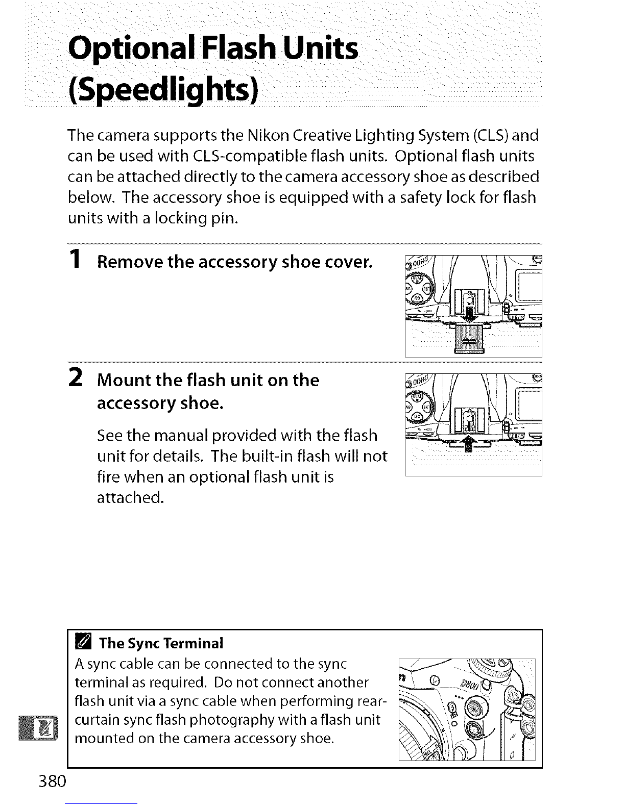
The Nikon Creative Lighting System (CLS)
Nikon's advanced Creative Lighting System (CLS) offers improved
communication between the camera and compatible flash units
for improved flash photography.
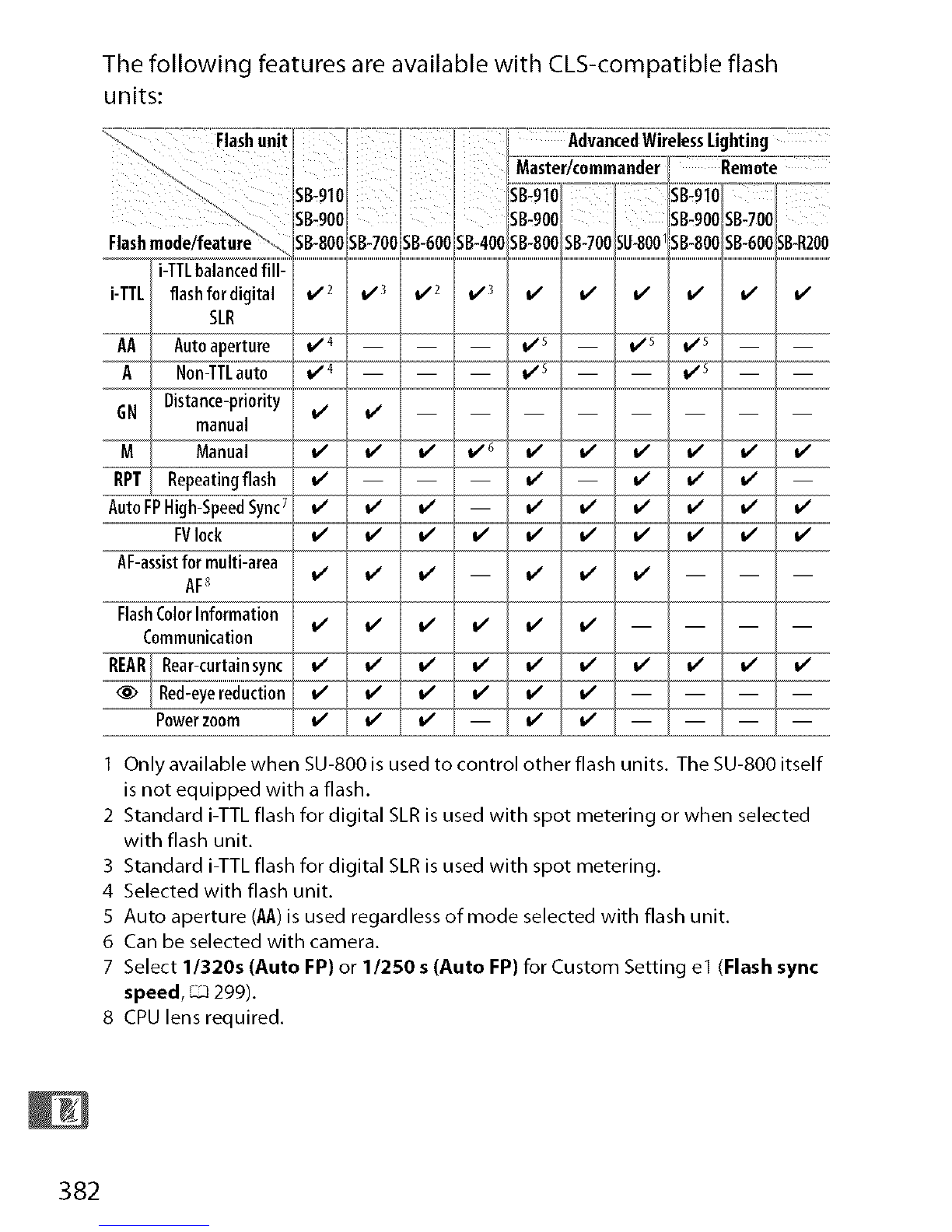
II CLS-CompatibleFlashUnits
The camera can be used with the following CLS-compatible flash
units:
• TheSB-910,SB-900,SB-800,SB-700,SB-600,SB-400,andSB-R200:
I Ira color filter is attached to the SB-910, SB-900, or SB-700 when AUTOor
(flash) is selected for white balance, the camera will automatically detect the
filter and adjust white balance appropriately.
2 Wireless flash control is not available with the SB-400.
3 Controlled remotely with built-in flash in commander mode or using optional
SB-91 O,SB-900, SB-800, or SB-700 flash unit or SU-800 wireless Speedlight
commander.
4 m/ft, 20 °C (68 °F), SB-910, SB-900, SB-800, SB-700, and SB-600 at 35 mm zoom
head position; SB-91 O,SB-900, and SB-700 with standard illumination.
•SU-800WirelessSpeedlightCommander:When mounted on a CLS-
compatible camera, the SU-800 can be used asa commander for
remote SB-91O,SB-900, SB-800, SB-700, SB-600, or SB-R200 flash
units in up to three groups. The SU-800 itself is not equipped
with a flash.
[] Guide Number
To calculate the range of the flash at full power, divide the Guide
Number by the aperture. For example, at ISO I O0the SB-800 has a Guide
Number of 38 m or 125 ft (35ram zoom head position); its range at an
aperture of f/5.6 is 38+5.6 or about 6.8 meters (or in feet,
125 +5.6=approximately 23 ft 7 in.). For each twofold increase in ISO
sensitivity, multiply the Guide Number by the square root of two
(approximately 1.4).
381

The following features are available with CLS-compatible flash
units:
' _,,, NsB-91ol i_B:_3_°_!IT'°7°lSi3:93oT-:7=_[°=:-_
UsB-9oo sB-9oo U LsB-9°°lsBa°°
as,
i-TTL flashf0rdigitalSLR_"_ _"' _2 _ .................
AA Autoaperture 1,15
i
A Non-TTLauto _s
GN Distance-priority E
manual v v
MManual v_
RPT Repeatingflash
Auto FPHigh-SpeedSync7_ _ _ _ V _ _ ]
FVlock v_v_
AF-assistfor multi-area _ _
AF8 v v ,#
FlashColorInformation
Communication v v v_v_v_
R_R Rear-curtainsyncv__ _ _ _
Red-eyereduction v______ l/
Powerzoom v..........._ .............................
IOnly available when SU-800 is used to control other flash units. The SU-800 itself
is not equipped with a flash.
2 Standard i-TTL flash for digital SLR is used with spot metering or when selected
with flash unit.
3 Standard i-TTL flash for digital SLR is used with spot metering.
4 Selected with flash unit.
5 Auto aperture (AA)is used regardless of mode selected with flash unit.
6 Can be selected with camera.
7 Select 1/3205 (Auto FP) or 1/250 s (Auto FP) for Custom Setting el (Flash sync
speed, _299).
8 CPU lens required.
382

[] Other Flash Units
The following flash units can be used in non-TTL auto and manual
modes.
m _ m
v' v' v' v'
v' v' v' v'
IFlash mode isautomatically set to TTL and shutter-release is disabled. Set flash
unit to A(non-TTL auto flash).
2 Autofocus isavailable with AF-SVRMicro-Nikkor 105mm f/2.8G IF-EDand AF-S
Micro NIKKOR60mm f/2.8G EDlenses only.
3 Available when camera isused to select flash mode.
[] Auto Aperture/Non-TTL Auto
Unless the focal length and maximum aperture are specified using the
Non-CPU lens data option in the setup menu (_ 213), choosing auto
aperture (AA)when a non-CPU lens is attached automatically selects non-
TTL auto (A).
383

_I_ Notes on Optional Flash Units
Refer to the flash unit manual for detailed instructions. If the unit
supports CLS, refer to the section on CLS-compatible digital SLR
cameras. The D800 is not included in the "digital SLR" category in the
SB-8ODX, SB-28DX, and SB-5ODX manuals.
i-TTL flash control can be used at ISO sensitivities between 1O0and 6400.
At values over 6400, the desired results may not be achieved at some
ranges or aperture settings. If the flash-ready indicator blinks for about
three seconds after a photograph is taken, the flash has fired at full
power and the photograph may be underexposed. View the
photograph in the monitor; if it is underexposed, adjust aperture, ISO
sensitivity, or the distance to the subject and try again.
When an SC-series 17, 28, or 29 sync cable is used for off-camera flash
photography, correct exposure may not be achieved in i-TTL mode. We
recommend that you select standard i-TTL flash control. Take a test shot
and view the results in the monitor.
In i-TTL, use the flash panel or bounce adapter provided with the flash
unit. Do not use other panels such as diffusion panels, as this may
produce incorrect exposure.
384

The SB-910, SB-900, SB-800, SB-700, SB-600, and SB-400 provide red-eye
reduction, while the SB-910, SB-900, SB-800, SB-700, SB-600, and SU-800
3rovide AF-assist illumination with the following restrictions:
•$B-910and $B-900:AF-assist
illumination is available with 17-
135 mm AF lenses, however,
autofocus is available only with
the focus points shown at right.
•SB-800,$B-600,andSU-800:AF-assist
illumination is available with 24-
105 mm AF lenses, however,
autofocus is available only with
the focus points shown at right.
•$B-700:AF-assist illumination is
available with 24-135 mm AF
lenses, however, autofocus is
available only with the focus
points shown at right.
17-19mm 20-105mm 106-135mm
_L D o w !!; _!]i]i: ¸¸¸
24-34mm 35-49mm 50-105mm
24-27mm 28-135mm
In exposure mode P,the maximum aperture (minimum f-number) is
limited according to ISOsensitivity, asshown below:
_=,::::::::::::::::::::,_o__:::::::::_i°m_u_m_a_ri_°_°_s_°e_u°__i__?o_°_,=__ ::::::::::::::__o___o:::_o_:
Ifthe maximum aperture of the lens is smaller than given above, the
maximum value for aperture will be the maximum aperture of the lens.
385

[] Flash Control Mode
The information display shows the flash control mode for optional flash
units as follows:
Autoaperture(AA)
Non,TTLautoflash(A)
Distance-prioritymanual
(GN)
Flashsync AutoFP(_-_300)
Manual _I'_ _I'_'_FMP
Repeatingflash ;_•p
lighting
_1_ Use Only Nikon Flash Accessories
Use onlyNikon flash units. Negative voltages or voltages over 250 V
applied to the accessory shoe could not only prevent normal operation,
but damage the sync circuitry of the camera or flash. Before using a
Nikon flash unit not listed in this section, contact a Nikon-authorized
service representative for more information.
386

Atthetimeof
theD800. writing,thefollowingaccessorieswereavailablefor
• RechargeableLi-ionBatteryEH-EL15(L:_19, 21): Additional
EN-EL15 batteries are available from local retailers and
Nikon service representatives. These batteries can be
recharged using an MH-25 battery charger.
•BatteryChargerMH-25(L_ 19): The MH-25 can be used to
recharge EN-EL15 batteries.
• Multi-Power BatteryPackMB-D12:The MB-D12 is equipped
with a shutter-release button, AF-OHbutton, multi selector,
and main- and sub-command dials for improved
operation when taking photographs in portrait (tall)
orientation. When attaching the MB-D12, remove the
Powersources camera MB-D12 contact cover. A BL-5 battery-chamber
cover and an MH-26 battery charger are required when
using EN-EL18 batteries.
•PowerConnectorEP-SB,ACAdapterEH-Sb:These accessories can
be used to power the camera for extended periods (EH-Sa
and EH-5 AC adapters can also be used). A power
connector EP-SB isrequired to connect the camera to the
EH-Sb, EH-Sa, or EH-5; see page 391 for details. Note that
when the camera is used with an MB-D12, the EP-SB must
be inserted into the MB-D12, not the camera. Do not
attempt to use the camera with power connectors
inserted into both the camera and MB-D12.
WirelessTransmitterWT-4:Connects the camera to wireless and
Ethernet networks. The photographs on the camera
memory card can be viewed by computers on the same
WirelessLAN network or copied to a corn puter for long-term storage. The
camera can also be controlled from any computer on the
adapters network using Camera Control Pro 2 (available separately).
(_-_J245) Note that the WT-4 requires an inde pendent power source
in the form of an optional EH-6b AC adapter or EN-EL3e
battery. See the WT-4 manual for details. Always use the
latest version of the WT-4 software.
387

iii i
iiii iii_
i/i i iii iiiii
ii ii ii ii_
iiiiiii i:(iii iiiii •
iililiiiii! ii/i iiii
_i i_ii I _.
Viewflnder
eyepiece
accessories
RubberEyecupDK-19:The DK-19 makes the image in the
viewfinder easier to see, preventing eye fatigue.
Diopter-AdjustmentViewfinderLensDK-17C:To accommodate
individual differences in vision, viewfinder lenses are
available with diopters of-3, -2, O,+1, and +2 m 1. Use
diopter adjustment lenses only if the desired focus can
not be achieved with the built-in diopter adjustment
control (-3 to +1 m 1). Test diopter adjustment lenses
before purchase to ensure that the desired focus can be
achieved. The DK-17C is equipped with a safety lock.
MagnifyingEyepieceDK-17M:The DK-17M magnifies the view
through the viewfinder by approximately 1.2 x for greater
precision when framing. The DK-17M is equipped with a
safety lock.
EyepieceMagnifierD6-2:The DG-2 magnifies the scene at the
center of the viewfinder for more accurate focus. DK-18
eyepiece adapter (available separately) required.
EyepieceAdapterDK-18:The DK-18 is used when attaching
the DG-2 magnifier or DR-3 right-angle viewing
attachment to the D800.
AntifogFinderEyepieceDK-14/AntifogFinderEyepieceDK-17A:
These viewfinder eyepieces prevent fogging in humid or
cold conditions. The DK-17A is equipped with a safety
lock.
Right-AngleViewingAttachmentDR-S/Right-AngleViewing
Attachment DR-4:The DR-5 and DR-4 attach to the
viewfinder eyepiece at a right angle, allowing the image in
the viewfinder to be viewed from above when the camera
is in the horizontal shooting position. The DR-5 supports
diopter adjustment and can also magnify the view
through the viewfinder by 2 x for greater precision when
framing (note that the edges of the frame will not be
visible when the view is magnified).
388

interfere with autofocus or the electronic rangefinder.
• The D800 can not be used with linear polarizing filters.
Use the C-PL or C-PLII circular polarizing filter instead.
• Use NC filters to protect the lens.
• To prevent ghosting, use of a filter is not recommended
Filters when the subject is framed against a bright light, or when
a bright light source is in the frame.
• Center-weighted metering is recommended with filters
with exposure factors (filter factors) over 1x (Y44, Y48,
Y52, O56, R60, X0, Xl, C-PL, ND2S, ND4, ND4S, ND8, ND8S,
ND400, A2, A12, B2, B8, B12). See the filter manual for
details.
_°_Z'::_ PCCardAdapterEC-ADI'The EC-AD1 PCcard adapter allows
PCcard Type I CompactFlash memory cards to be inserted in
adapters PCMCIA card slots.
• CaptureHX2: A complete photo editing package with such
advanced editing features as selection control points and
an auto retouch brush.
•CameraControlPro2: Control the camera remotely' from a
computer and save photographs directly to the computer
hard disk.
Software Note:Usethe latest versions of Nikon software; see the websites
listed on page xx for the latest information on supported
perating systems. At default settings, Nikon Message Center 2
will periodically check for updates to Nikon software and
firmware while you are logged in to an account on the
computer and the computer isconnected to the Internet. A
message isautomatically displayed when an update isfound.
_-_ _-_ii BodyCapBF-1B/BodyCapBF-1A:The body cap keeps the mirror,
Bodycaps viewfinder screen, and low-pass filter free of dust when a
lens is not in place.
_--_°_i_ _ StereoMicrophoneME-1(_ 65): Connect the ME-1 to the
Microphones camera microphone jack to record stereo sound while
reducing the noise caused by lens vibration being recorded
with movies during autofocus.
389

for remote control and automatic photography. The
terminal is provided with a cap, which protects the contacts
when the terminal is not in use. The following accessories
can be used (all lengths are approximate):
• RemoteCordMC-22:Remote shutter release with blue, yellow,
and black terminals for connection to a remote shutter-
triggering device, allowing control via sound or electronic
signals (length 1 m/3 ft 3 in.).
•RemoteCordMC-30:Remote shutter release; can be used to
reduce camera shake (length 80 cm/2 ft 7 in.).
•RemoteCordMC-36:Remote shutter release; can be used for
interval timer photography or to reduce camera shake or
keep the shutter open during a time exposure (length
Remote 85 cm/2 ft 9 in.).
terminal •ExtensionCordMC-21:Can be connected to ML-3 or MC-series
accessories 20, 22, 23, 25, 30, or 36. 0nly one MC-21 can be used ata
time (length 3 m/9 ft 10 in.).
•ConnectingCordMC-23:Connects two cameras for
simultaneous operation (length 40 cm/1 ft 4 in.).
•AdapterCordMC-25:Ten-pin to two-pin adapter cord for
connection to devices with two-pin terminals, including
theMW2rad ocontrolset,MT2intervalometer,andMk2
modulite control set (length 20 cm/8 in.).
•GPSUnit GP-1(_ 215): Record latitude, longitude, altitude,
and UTCtime with pictures.
•GPSAdapterCordMC-35(_ 216): Connects GPS devices to
D800 via PC cable supplied by manufacturer of GPS device
(length 35 cm/1 ft 2 in.).
•ModuliteRemoteControl SetML-3:Allows infrared remote
control at ranges of up to 8 m (26 ft 3 in.).
390

Attaching a Power Connector and AC
Adapter
Turn the camera off before attaching an optional power connector
and AC adapter.
Ready the camera.
Open the battery-chamber ((1_)and
power connector (_2_)covers.
2Insert the EP-5B power connector.
Be sure to insert the connector in the
orientation shown, using the connector
to keep the orange battery latch pressed
to one side. The latch locks the connector
in place when the connector is fully
inserted.
3Close the battery-chamber cover.
Position the power connector cable so
that it passes through the power
connector slot and close the battery-
chamber cover.
391

4, Connect the AC adapter.
Connect the AC adapter power cable to the AC socket on AC
adapter (_3_)and the EP-SB power cable to the DC socket (_4_).
When the camera is powered by the AC adapter and power
connector, the battery level display in the monitor turns off.
392

Storaqe
When the camera will not be used for an extended period, remove
the battery and store it in acool, dry area with the terminal cover in
place. To prevent mold or mildew, store the camera in a dry, well-
ventilated area. Do not store your camera with naphtha or
camphor moth balls or in locations that:
• are poorly ventilated or subject to humidities of over 60%
• are next to equipment that produces strong electromagnetic
fields, such as televisions or radios
• are exposed to temperatures above 50 °C (122 °F) or below
-10 °C (14 °F)
Cleaning
Use a blower to remove dust and lint, then wipe gently with a
soft, dry cloth. After using the camera at the beach or seaside,
Camera wipe off sand or salt with a cloth lightly dampened in distilled
water and dry thoroughly. Important: Dust or other foreign
matter inside the camera may cause damage not covered under
warranty.
These glass elements are easily damaged. Remove dust and
lint with a blower. If using an aerosol blower, keep the can
mirror,and vertical to prevent the discharge of liquid. To remove
viewfinder fingerprints and other stains, apply a small amount of lens
cleaner to a soft cloth and clean with care.
Remove dust and lint with a blower. When removing
f ngerpr nts and other sta ns wipe the surface lightly with a
Monitor soft cloth or chamois leather. Do not apply pressure, as this
could result in damage or malfunction.
Do not use alcohol thinner, or other volatile chemicals.
393

The Low-Pass Filter
The image sensor that acts as the camera's picture element is fitted
with a low-pass filter to prevent moire. If you suspect that dirt or
dust on the filter is appearing in photographs, you can clean the
filter using the Clean image sensor option in the setup menu. The
filter can be cleaned at any time using the Clean now option, or
cleaning can be performed automatically when the camera is
turned on or off.
II "CleanNow"
1 Place the camera base down.
Image sensor cleaning is most effective
when the camera is placed base down as
shown at right.
2Select Clean image
sensor in the setup
menu.
PressMENUto display the
menus. Highlight Clean
image sensor in the setup
menu and press I_. T
MENUbutton
394

3Select Clean now.
Highlight Clean now and
press _. The camera will
check the image sensor
and then begin cleaning.
This process takes about
ten seconds; during this
time, buS-_ is displayed in
the control panel and other
operations can not be
performed. Do not remove
or disconnect the power
source until cleaning is
complete and bu 5-_ is no
longer displayed.
Q button
395
Other manuals for D800E
3
This manual suits for next models
1
Other Nikon Digital Camera manuals

Nikon
Nikon COOLPIX P100 User manual

Nikon
Nikon D850 Quick start guide

Nikon
Nikon Coolpix S640 User manual

Nikon
Nikon CoolPix S560 User guide

Nikon
Nikon D500 Quick start guide

Nikon
Nikon COOLPIX P71 00 User manual

Nikon
Nikon COOLPIX 3700 Operating instructions

Nikon
Nikon COOLPIX L810 User manual

Nikon
Nikon D700 User manual

Nikon
Nikon COOLPIX A User manual