Nikon V-14 User manual

Nikon/PROFILE PROJECTOR
MODEL V-14
------
INSTRUCTIONS
NIPPON KOGAKU KlIK.

CONTENTS
NOMENCLATURE 2
OPTICAL SySTEM 3
§1. FUNCTION OF EACH PART
1.
2.
3.
4.
5.
6.
7.
8.
9.
10.
11.
12.
13.
14.
15.
16.
17.
~8.
19.
20.
USING
1.
§2.
Viewing screen 4
Screen lock 4
Chart clips 4
Hood 4
Turret lens mount 4
Projection lenses 5
Anti·glare shield 5
Stage mount 5
Change·over knob for contour illumination 5
Contour illuminator 6
Surface illuminator 6
Surface illuminator support 6
Focusing wheel 7
Cabinet 7
Power socket 7
Fuse 7
Main switch 8
Contour illuminator switch 8
Surface illuminator switch 8
Dial gage eyelet ' 8
Illumination 9
(1) Contour illumination 9
Detection of the correct position of lamp 9
Changing·over the condenser 10
(2) Surface illumination 10
Oblique illumination 10
Vertical illumination : 10
2. Projection 11
(1) Correct positioning 11
(2) Sharp focusing 11
(3) Centering 12
3. Measurement 13
(1) Placing a scale on the screen 13
(2) Comparing with standard length 14
(3) Comparing with master chart 14
(4) Measuring angle by rotating the screen 15
(5) Tracing screen images 16
(6) Photographing screen image 16
CAUTION IN HANDLING
1. Screen 17
2. Projection lens 17
3. Mirrors 17
4. Half·reflecting mirror 17
5. Dark image 18
6. Lamp bulb 18
7. Others 18
8. If something wrong or disorder is found 18
TECHNICAL DATA 19
SPECIAL ACCESSORIES 22
-1~

NOMENCLATURE
Turret lens mount
Switches
Projection lenses
MI crometer stage type 0
Surf ace ill umi nator support
Stage mount
Screen lock
Screen
Chart clip
FOCUSI ng wheel
Dial gage mount
Antiglare shield
Cabi net
Surf ace ill umi nator
Condenser change-over knob
Cooling fan
Contour illuminator
Fuse
Power cord
Fig. 2
2
Fig. 1

OPTICAL SYSTEM
Half-reflecting mirror
Stage gloss
Dust-tight glass
- 3 -
Screen
Projection lens
Heat absorbing filter
Condenser lens
Heat absorbing filter
lamp
Fig. 3

The viewing screen is interchangeable with
Protractor or Photographing Screen, both
available on order. Onto the metal frame
of the screen, not only the chart clips but
the reading scale, available on order, can
be attached.
§1.
1. Viewing screen
FUNCTION OF EACH PART
(Fig. 4)
Fig. 4
The screen is fastened to the instrument
with the lock on the top and is released
by turning the lock counterclockwise (Fig.
5a) to the position as shown in Fig. 5b.
2. Screen lock
3. Chart clips
(Fig. 5)
(Fig. 4)
",\\\
~
aFig. 5 b
The chart clips serve to firmly hold a sheet of paper or plastic to be used as a master
chart on the screen.
Pull the clip head, and the clip will be released and can be turned.
It is detached from the screen by unscrewing its milled part.
4. Hood (Fig. 4)
In case extraneous light obstracts the observation of the screen image, pull the hood
forward. The hood can be pushed backward when not in use.
Three projection lenses, mounted on the turret,
are changed over one after another by turning
the turret. Rotate the turret holding two of
the three knobs with both hands so that the
lens to be used faces toward the user, where
it click-stops exactly in the optical axis.
5. Turret lens mount (Fig. 6)
Fig. 6
- 4 -

6. Projection lenses (Fig. 7)
(Available on order')
To screw in or out the lens from the turret,
hold its milled part.
To exchange the lens, do not forget to lower
the stage beforehand.
The projection lens with a built-in half-reflecting
mirror has the lower end rotating around the
optical axis, so that the mirror can be faced
toward the surface illuminator.
Fig. 7
7. Anti.glare shield (Fig. 2)
The shield can be swung freely around the vertical and horizontal axis.
It serves for preventing glare caused by scattering light from the surface of specimen.
The shield can be detached from the instrument by rotating the black knurled part.
8. Stage mount (Fig. 8)
Release beforehand the knurled screw on the right-hand bottom of the stage to be
mounted.
Place the stage over the central protrusion on the mount.
Fasten the stage to the mount by means of the knurled screw.
The micrometer stage should be fastened in such a position that the crosswise travelling
directions coincide with the cross lines engraved on the screen.
Be careful enough in handling the stage to keep its high accuracy.
As to the specifications of the stages, refer to the tables on p. 20.
9. Change·over knob for contour illumination (Fig. 8)
Releasing the milled knob by turning counter-
clockwise, move it downward, and the conver-
gence of illuminating light will be changed
continuously. For projection 100x or higher,
fasten the knob in the position 100 x .
- 5 -
Fig. 8

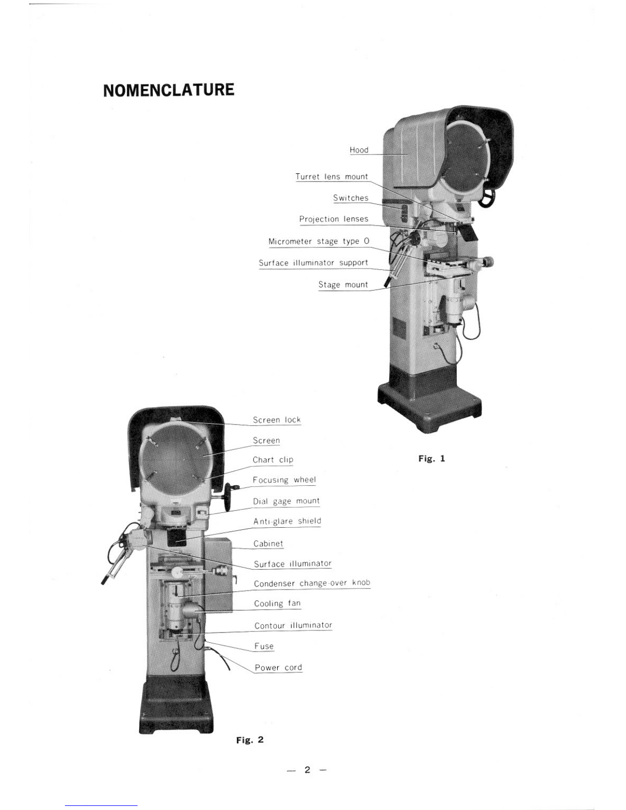
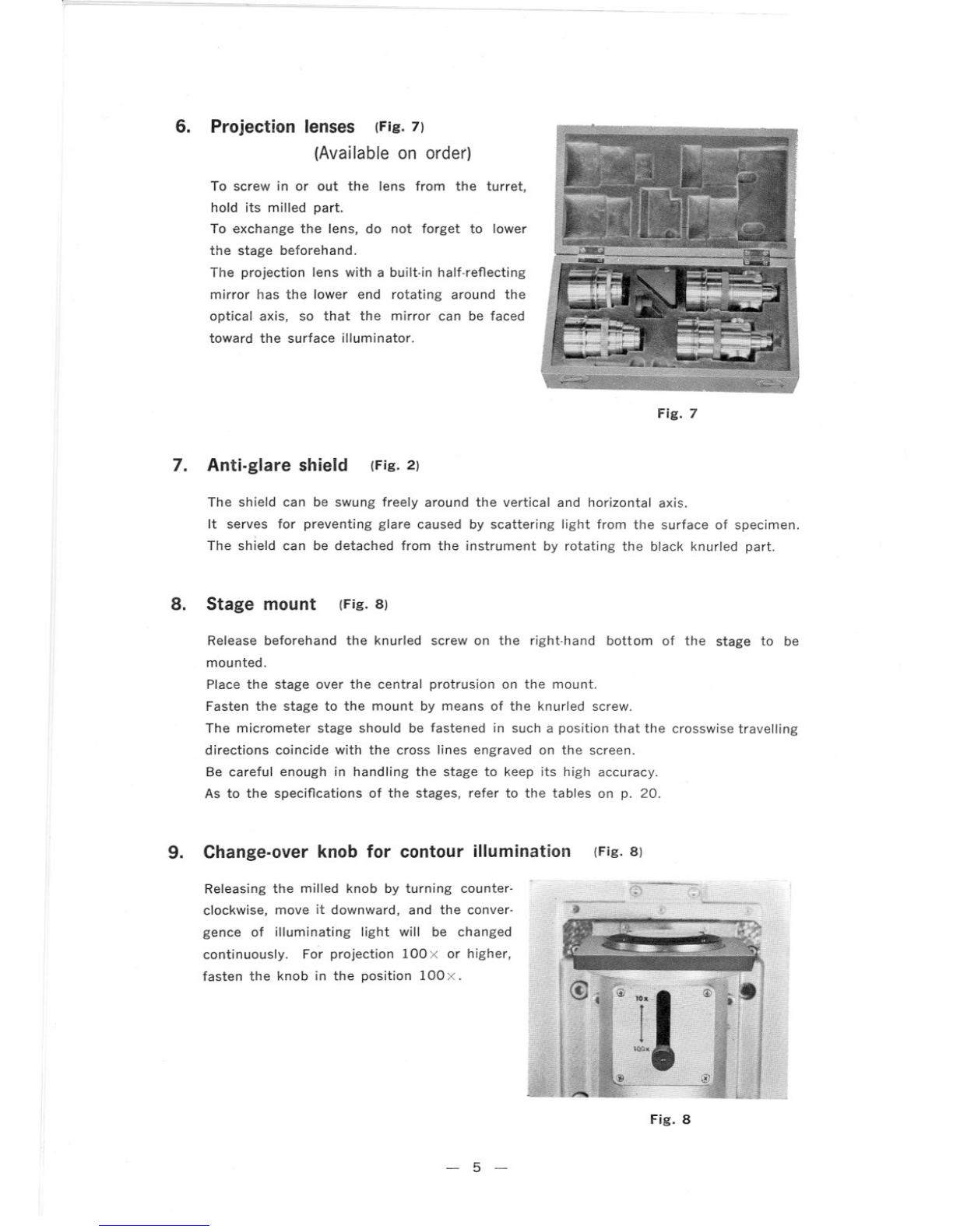
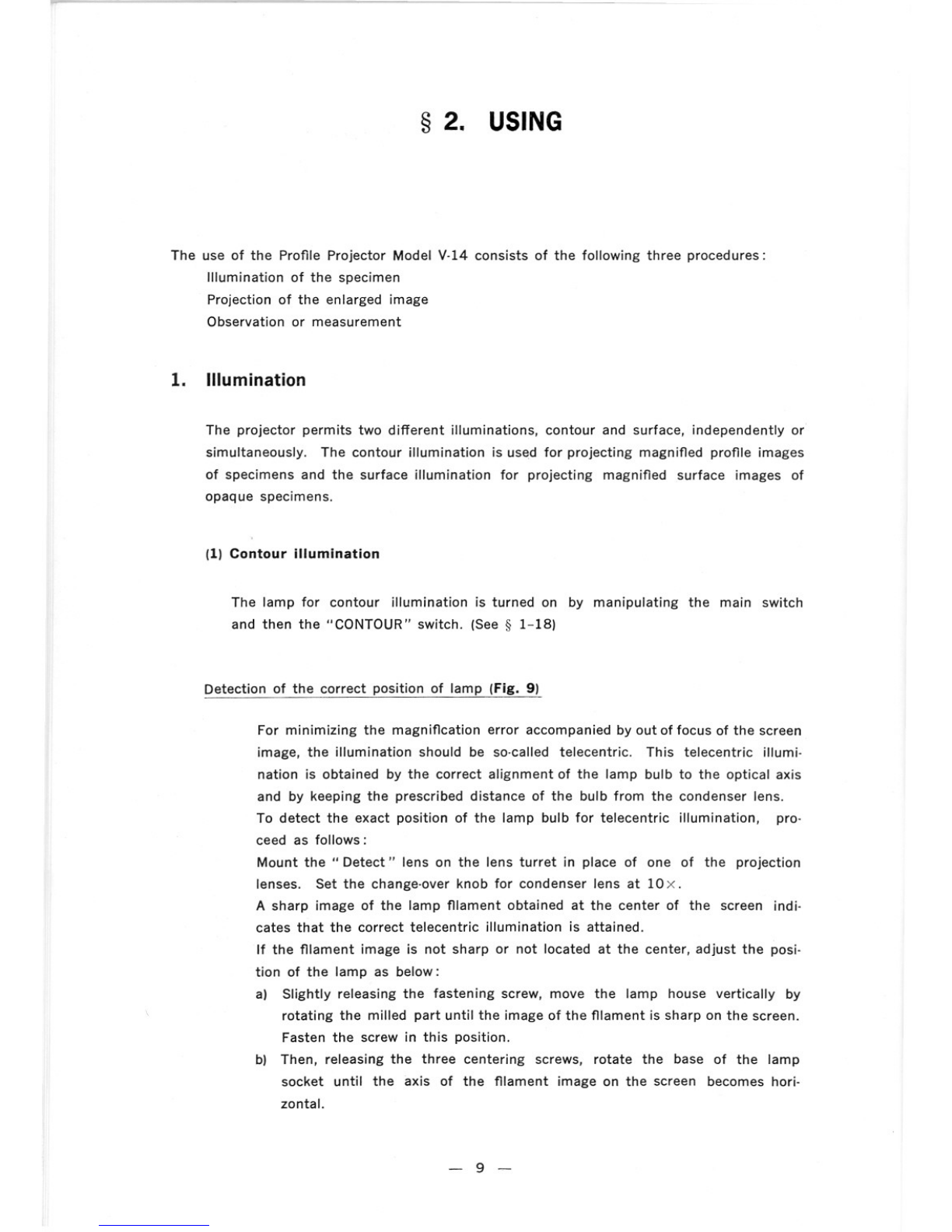
10. Contour illuminator (Fig. 9)
To take out the lamp house, slightly release
the fastening sCrew, turning clockwise (viewed
from above) the knurled part, pull out the lamp
house downward.
For replacement, insert the lamp house with
the top end of the groove faced toward the
side opposite to the fastening screw. Push in
the house by turning counterclockwise. Lock
it in position with the fastening screw.
Three screws are provided for centering the
lamp. These screws being released, the lamp
can be rotated by turning the base of the
lamp socket.
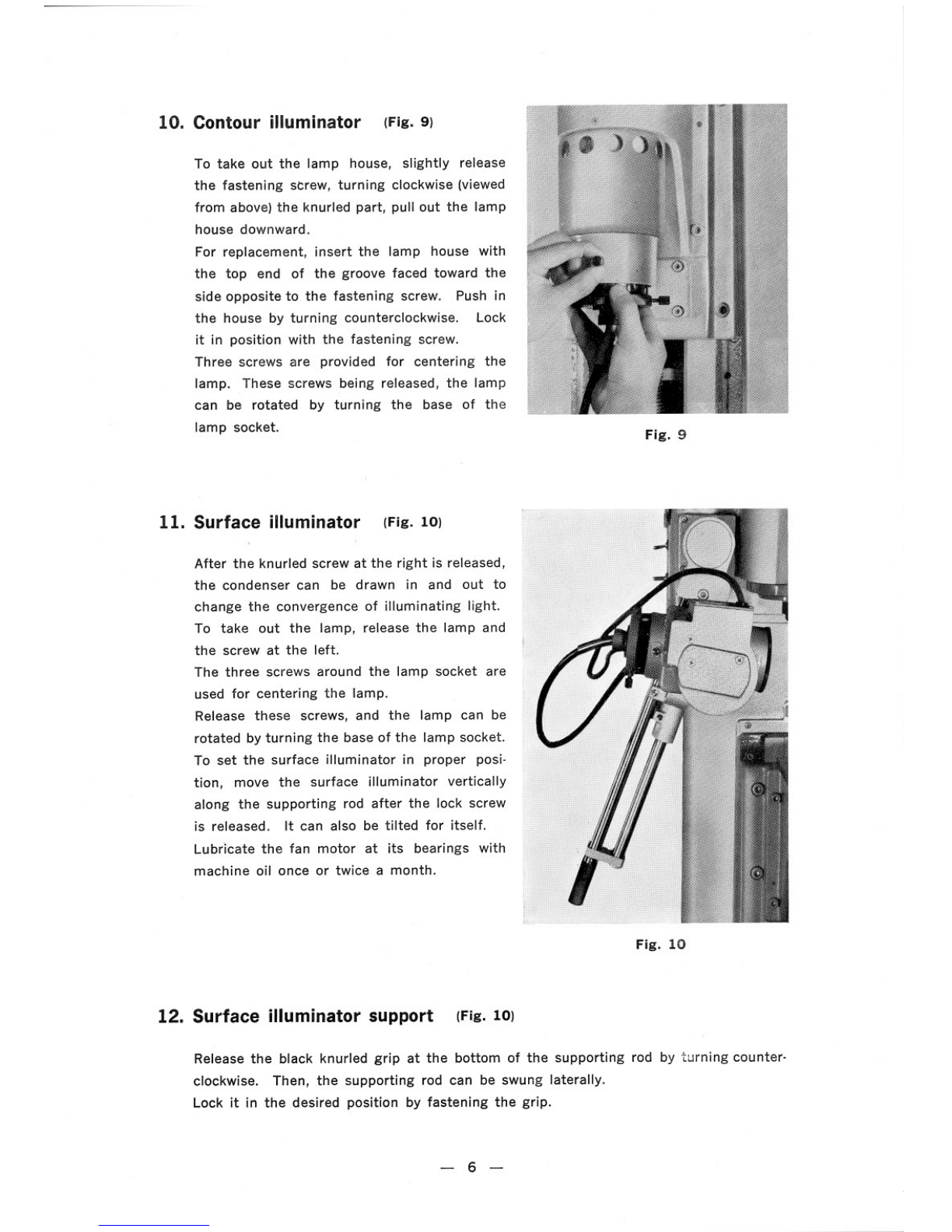
11. Surface illuminator (Fig. 10)
After the knurled screw at the right is released,
the condenser can be drawn in and out to
change the convergence of illuminating light.
To take out the lamp, release the lamp and
the screw at the left.
The three screws around the lamp socket are
used for centering the lamp.
Release these screws, and the lamp can be
rotated by turning the base of the lamp socket.
To set the surface illuminator in proper posi-
tion, move the surface illuminator vertically
along the supporting rod after the lock screw
is released. It can also be tilted for itself.
Lubricate the fan motor at its bearings with
machine oil once or twice a month.
12. Surface illuminator support (Fig. 10)
Fig. 9
Fig. 10
Release the black knurled grip at the bottom of the supporting rod by turning counter-
clockwise. Then, the supporting rod can be swung laterally.
Lock it in the desired position by fastening the grip.
- 6 -

13. Focusing wheel (Fig. 14)
Turning of the wheel moves the stage vertically in a range of about 180mm.
One rotation of the wheel moves the stage about 2 mm.
The wheel is provided with a device which stops the movement of the stage when this
comes to the top and bottom limit. Beyond these limits the wheel cannot be turned.
Operate the wheel gently at the neighborhood of these limits.
(After the instrument is installed, the removal of the red·colored bolts (Fig. 29) is
necessary.)
14. Cabinet (Fig. 11)
(Available on order)
The accessory cabinet can be attached to
either side of the instrument by means of 4
bolts supplied with the instrument. Move the
inside shelves to the bottom, and the lens case
can be stored in the cabinet.
Fig. 11
16. Fuse (Fig. 12)
To replace the fuse, take out the fuse cover
by turning in the direction of the arrow.
The socket accepts the power cord plug.
Fasten it with the nut outside of the plug.
The sockets for illuminators and for the cooling
fans are manipulated likewise.
(Fig. 12)
15. Power socket
Fig. 12
- 7 -

18. Contour .illuminator switch (Fig. 13)
Switch on the" MAIN switch", and the electric
current will flow to the primary circuit of the
built-in transformer. After using the projector,
never forget to switch off.
Turning" CONTOUR" switch to H or L, lights
the lamp for Contour illuminator and at the
same time the cooling fan starts running.
In the H position the brightness will be increas-
ed and in the L position it will be decreased,
the life of the lamp bulb being elongated about
three times by using at this position.
Fig. 13
(Fig. 13)17. Main switch
19. Surface illuminator switch (Fig. 13)
The left-hand "SURFACE" switch is manipulated in the same way as the right-hand
"CONTOUR ".
The larger socket below the switch panel is for power supply for the surface illuminator
and the smaller one for the cooling fan.
20. Dial gage eyelet (Fig. 14)
A dial gage attached to the eyelet on the
projector body, using the supporting rod which
is available on order, permits height or depth
measurement.
Move the projector stage vertically to take
reading of the dial gage at each sharply
focused position. The inner diameter of the
dial gage mounting hole is 6.5mm with coun-
terbore diameter 18mm.
In place of the dial gage eyelet, the right-
hand surface illuminator can be attached for
both-side oblique illuminations along with the
left-hand illuminator. For power supply to the
right-hand illuminator and for its cooling fan,
use the power socket and cooling fan socket
for the" Contour Illuminator" respectively.
Fig. 14
- 8 -

§2. USING
The use of the Profile Projector Model V-14 consists of the following three procedures:
Illumination of the specimen
Projection of the enlarged image
Observation or measurement
1. Illumination
The projector permits two different illuminations, contour and surface, independently or
simultaneously. The contour illumination is used for projecting magnified profile images
of specimens and the surface illumination for projecting magnified surface images of
opaque specimens.
(1) Contour illumination
The lamp for contour illumination is turned on by manipulating the main switch
and then the "CONTOUR" switch. (See §1-18)
Detection of the correct position of lamp (Fig. 9)
For minimizing the magnification error accompanied by out of focus of the screen
image, the illumination should be so-called telecentric. This telecentric illumi·
nation is obtained by the correct alignment of the lamp bulb to the optical axis
and by keeping the prescribed distance of the bulb from the condenser lens.
To detect the exact position of the lamp bulb for telecentric illumination, pro-
ceed as follows:
Mount the" Detect" lens on the lens turret in place of one of the projection
lenses. Set the change-over knob for condenser lens at 10 x.
A sharp image of the lamp flIament obtained at the center of the screen indio
cates that the correct telecentric illumination is attained.
If the filament image is not sharp or not located at the center, adjust the posi·
tion of the lamp as below:
a) Slightly releasing the fastening screw, move the lamp house vertically by
rotating the milled part until the image of the flIament is sharp on the screen.
Fasten the screw in this position.
bl Then, releasing the three centering screws, rotate the base of the lamp
socket until the axis of the flIament image on the screen becomes hori·
zontal.
- 9 -

c) Then, manipulate the three centering screws so that the filament image
comes to the center of the screen.
The above adjustment once exactly established, holds good for other projec-
tion lenses and will not be necessary so long as the lamp bulb is not
replaced.
Detach the" Detect" lens from the turret and replace it with another pro-
jection lens.
Changing-over the condenser (Fig. 8)
With the change-over knob positioned at the top, the largest illuminated field
will be obtained. As it is lowered, the illuminated area will be smaller.
Fasten the knob in the position where uniform brightness throughout the entire
area of the screen is attained for each magnification.
(2) Surface illumination
Two surface illuminations, oblique and
vertical, are possible.
To turn on the surface illuminator lamp,
switch on the "MAl N " and then "SU R-
FACE" (See ~ 1-19). As to the mani-
pulation of the surface illuminator and
its support. (See ~ 1-12) Fig. 15
Oblique illumination (Fig. 15)
For this illumination, throw the light of
the surface illuminator from above slant-
wise onto the specimen surface being
observed. Unevenness of the surface will
be seen in relief, so that the illumination
is suitable for inspecting scratches on a
smooth surface, for examining patterns,
cloth, paper, etc.
The best result will be attained when the
brightest image is obtained by adjusting
the position and inclination of the surface
illuminator and the convergence of light.
In this type of illumination, light supplied
by the surface illuminator is thrown from
above vertically down to the surface to
be observed.
- 10 -
,
Fig. 16
Fig. 17

For this purpose, the use of a half-reflecting mirror is necessary on the projection
lens. Such an illumination is suited for inspecting smooth shiny surfaces, engraved
graduation, pattern, etc.
Slip on the half-reflecting mirror to the projection lens 10 X or 20 X. When using
the projection lens 50X or 100x, bring the built-in half-reflecting mirror to an angle
of 45 degrees by turning the small outside knob counterclockwise as far as it will go,
For the other types of illuminations, turn the knob in the reverse direction to bring
the mirror away out of the light path.
Important points for the correct surface illumination are as follows:
1. Face the half-reflecting mirror correctly toward the surface illuminator, other-
wise the brightness on the projected image will not be obtained equal at the
top and the bottom.
2. Throw the light exactly toward the center of the window glass, or the image
will show a brightness difference at the right and the left.
3. Supply the light to a full extent to avoid darkness or brightness difference at
the center and at the periphery of the screen.
Depending upon whether the oblique or vertical illumination is used, the position
and inclination of the surface illuminator and the convergence of the light should be
differently adjusted. Even in the same type of illumination, the most suitable lighting
conditions are not the same according to the magnification chosen. Therefore, it is
necessary, every time the type of illumination or magnification is changed, to adjust
the conditions so that the best illuminating effect, that is, the most and uniform
brightness is attained throughout the entire area of the screen.
(1) Correct positioning
In projecting the image, the procedures are
to be taken in the following order:
Fig. 18
(Fig. 18)
The surface or section of specimen to be
projected should be placed at a right angle
to the optical axis of the projection lens.
In case the specimen has a flat top surface
parallel to its flat bottom, it only needs to
place the specimen on the stage without
any flxture, because the surface of the
stage is exactly at a right angle
to the optical axis of the lens.
However, for specimens of cylin-
drical form, such as pin, shaft,
screw, etc., it is necessary to
employ a fixture, such as V-block
and center support (Fig. 19),
which holds them in position.
(2) Sharp focusing
Focusing is performed by rais-
2. Projection
Fig. 19
- 11 -

ing and lowering the stage by means of the focusing wheel. If sharpness is not
obtained over the entire screen image, make the surface or section of the specimen
to be. projected exactly at a right angle to the optical axis of lens. Insufficient
focusing will result in magnification error. This error may come out more serious
in the reflecting illumination.
Be careful in focusing not to thrust the specimen against the lens or the half-refiecting
mirror while viewing the screen image.
To avoid this, raise the stage so far that the clearance between specimen and lens
front be slightly less than the free working distance (see below) of the lens being
used. Then, looking the image on the screen, lower the stage slowly until the image
becomes plainly sharp.
Free Working Distances of Projection Lenses (mm)
Magnifi- Dia. of
A
B
D1D2
cation object field m
10 X 35.67628268180
20X 17.838810080
*
20X 17.86617210150
31.25 X 11.324245850--- Nikonl
*31.25X
11.34343116100 r"""'"
50X
7.115154233 ~ ~'Ji---r
*
50X 7.14444135118
62.5 X 5.611112722
0, J\~---LA
100X
3.5771613
*
100X 3.514143028
-t 0' '=f:-1-
*
200X 1.7882019
_/~,. _ B
*
300X 1.1882121
*
400X 0.8661212
*
500 X 0.7661212
Fig. 20
* 1000 X 0.3551111
In this table, the free working distance of each lens means a clearance between
the focal plane and the lens front (A) or the bottom end of half-refiecting mirror
(Bl. when the lens is critically focused to the specimen surface.
D1: Maximum diameter of a cylindrical specimen, the generatrix of which is pro-
jected at the center of the screen.
D2: Maximum diameter of a cylindrical specimen, the generatrix of which is pro-
jected at the edge of the screen.
*Long working distance type
(3) Centering
At lower magnifications, the portion of the image to be examined can easily be
brought to the center by moving the specimen by hand.
At a highe~ magnification, the use of the micrometer stage (Fig. 21), available on
order, in place of the regular stage will be convenient in positioning the specimen
exactly in the center.
It is a general principle in
higher magnifications to
bring the image to the
center, first using a lower
magnification lens and
then changing over to a
higher magnification lens.
Fig. 21
- 12-

3. Measurement
The Profile Projector permits the user not only to conveniently examine or inspect minute
details of the specimen by its enlarged image projected on the screen, but also to easily
and accurately determine or measure the dimensions of the specimen, because the instru·
ment has been designed to give the projected image with a high accuracy of magnifi·
cation throughout the entire screen area.
It is also noteworthy that from the nature of its measuring method, the Profile Projector
has great advantages in measuring the following types of specimen:
1. Too minute or small to be held in the end·to·end length measuring apparatus
2. Liable to deformation or damage under the measuring pressure
3. Such an irregular shape that the measurement is difficult or troublesome by means
of other instruments
The measuring methods with the Profile Projector should be various according to the
measured, accuracy of measurement required, etc. Several basic methods will be described
below:
(1) Placing a scale on the screen (Fig. 22)
Dimensions of the screen image can be measured using a scale on the screen sur·
face.
In this case, for reading of the scale, a magnifying glass may be used.
However, the use of a high power magnifying glass is not advisable, because diffi·
culty in determining the image contour will occur, due to the ground glass grains
of the screen coming in sight, and eye strain may not be avoided in prolonged work.
It is recommended to use a glass scale available on order (one type with one
division: 0.5 mm and the other: 0.1 mm), since the graduation viewed through the
glass can be brought into direct with the image on the screen, so that any measuring
error caused by parallax is avoided.
the
Fig. 22
- 13-

(2) Comparing with standard length
When inspection is to be repeated for a lot of specimens, it is convenient to draw
two fiducial lines on the screen glass with the interval corresponding to the standard
as shown in (Fig. 23), for example.
Measure a difference of the image from the standard using a scale, or more simply,
a screw micrometer equipped on the micrometer stage available on order, where the
difference is obtained not in the magnified but in the actual value directly.
Fiducial lines
Difference
Fig. 23
(3) Comparing with master chart
Inspection of a specimen of complicated shape as shown in (Fig. 24) can easily and
accurately be made by superposing the projected image on the master chart.
Needless to say that the chart should be drawn exactly at a prescribed magnification
and be held firmly on the screen adhesive.
When the line or figure representing the tolerance is given on the master chart
along with the fiducial one, it facilitates rapid inspection.
Fig. 24
- 14-

For master charts, translucent paper or plastic sheet will be used. However, if more
accurate work is required, paper adhered to transparent glass plate is recommended,
which can be brought into close contact with the screen surface only by using the
chart clips.
Plastic sheet can be handled more conveniently than glass, because of its light
weight and unbreakable property. But it is more liable to be scratched and has
greater thermal expansion and undergoes some dimensional change by age.
(4) Measuring angle by rotating the screen (Fig. 25,26)
The angle can be measured also by rotating the protractor screen available on
order.
First, bring one of the cross lines engraved on the screen into coincidence with
a side of the angle to be measured, the apex being in contact with the center of
the cross lines, and take reading of the angle on the protractor. Then, by rotating
the screen, bring the same line up to the other side of the angle and read the
protractor.
The difference between the two readings will give the angle to be measured.
Fig. 25 Fig. 26
In measuring a fairly large angle, it may be efficient to take the difference from the
right angle of the cross lines.
More rapid and convenient angle measurement will be performed by using the micro-
meter stage, in which it need not make the center of the cross lines coincide with
the apex of the angle to be measured.
It is noteworthy that, in bringing a side of the angle to the cross lines, a better
result will be obtained, if a slight clearance is made therebetween, by which the
coincidence error may be avoided.
- 15 -

(5) Tracing screen images
Comparison of two similarly shaped specimens is conveniently parformed byoverlay-
ing the screen image of one specimen traced on translucent paper upon the pro-
jected image of the other on the screen, or by placing both traced images of speci-
mens upon the other. If necessary, the traced images on the paper can be kept
for later use.
As paper is breakable and liable to expansion and contraction, it is not suitable for
accurate work and for use after a long period.
Sheet of plastic in place of paper may be better, though more expensive.
Plastic sheet with a mat surface on which fiducial lines or figures can be drawn
directly is available and also used as a master chart as described previously.
Fig. 27
focusing glass and a plate holder in which
When using the photographing screen, no
To take photograph, make the room
dark, hold a sheet of photosensitive
plate, film, paper, etc. on the screen
and give an appropriate exposure by
switching on and off the illuminator of
the projector.
There is a photographing screen,
available on order which is mounted
on the instrument in place of the
normal screen. It is provided with a
plate, film or paper is put beforehand.
dark room will be necessary.
No correct exposure time can be given here, because they vary with the surface of
specimen, type of illumination, magnification, voltage of the lamp being used, etc.
The surest way to determine the correct exposure is to expose a test plate in steps
of time and giving the best result. If the exposure time is too short to be controlled
in such a case where a high sensitive material is used, it will be better to decrease
the intensity of the lamp, or it will be convenient also to put in and out a piece of
cardboard underneath the projection 'lens, instead of switching on and off the lamp.
For accurate measurement, photographic plate is preferably used to paper as the
former is less liable to expansion or shrinkage.
The photograph of projected image
taken as a permanent record has an
advantage that it permits examination
and measurement at a later time.
(6) Photographing screen image (Fig. 27)
- 16 -

CAUTION IN HANDLING
The Profile Projector, being a high precision instrument, should be handled carefully enough
to maintain its accuracy. The place for setting up the instrument should be free as far as
possible from vibration, dirt, high temperature and moisture.
1. Screen
Grease or finger marks on the screen which will make the image undiscernible can be
washed out, using warm water with soap. For washing, do not detach the glass sepa-
rately, but with its metal frame, to avoid damage. Dry and then attach it to the
instrument.
2. Projection lens
Never attempt to disassemble the lens. Avoid rough handling and touching the lens sur-
faces with fingers or other things to prevent their anti-refiection coat from being
scratched.
3. Mirrors
Do not touch the mirrors built in the instrument to avoid changing of the position and
inclination which causes inaccurate magnification.
They have aluminium-plated surfaces which are liable to be scratched if touched or
rubbed. If need arises to take dirt or cloudiness off their surfaces, contact the maker
or his agent.
4. Half-reflecting mirror
The half-reflecting mirror built-in or to be attached to the projection lens for vertical
illumination is coated with an extremely thin metallic layer which is also liable to
be scratched. Take the same caution as for the mirrors above mentioned. Little dust
or dirt left on their surfaces will not affect the image quality. To take dirt off their
surfaces, use a soft feather. If not sufficient, use a wad of cotton soaked with ether
and sweep over them carefully to wash off the dirt or dust. Do not rub them.
- 17-

5. Dark image
7. Others
Should the lamp fail, check the lamp fila-
ment and the fuse.
Insufficient contact of the cord plug or of
the socket may cause failing of the lamp.
To detach the lamp bulb from the socket,
turn the bulb counterclockwise while depress-
ing. For attaching, reverse this procedure.
Be careful of the two differently sized notches
on the bayonet.
The vertical movement of the stage is locked
by two red-colored bolts.
Therefore, before manipulating the focusing
wheel, remove the bolts using a hexagonal
wrench. (Fig. 29)
For transportation, move the instrument
gently to avoid vibration and shock al5 far as
possible.
For installation, set up the stage surface
horizontal.
Fig. 28
(Fig. 28)
If the screen image is too dark, check the
lamp bulb after taking out.
If the glass surface of the bulb becomes
blackened, change the bulb with spare. Dust
on the surface also may c;:ausedarkness.
If darkness arises in the contour illumination,
check the stage glass and window glass
below.
Darkness in the surface illumination may be
caused by dirt on the glass elements in the
surface illuminator. Wipe off the dust with
a soft feather and linen soaked with alcohol.
6. Lamp bulb
Fig. 29
8. If something wrong or disorder is found
Contact the agent or the maker immediately without disassembling the instrument in
any way. For any other difficulties or troubles, we are always ready to furnish infor-
mation.
- 18-

TECHNICAL DATA
Screens
Effective diameter of screen: 356mm
Provided with cross lines engraved on fine grain ground glass
Equipped with 4 detachable chart clips
Glass scale, available on order, can be attached
Interchangeable with Protractor or Photographing Screen
Projection lenses (Available on order)
Magnification Diameter of Remarks
object field lOx
35.6mm
Half·reflecting mirror attached
20x
l7.8mm II
20x-L
II II
31.25x
11.3mm
Half-reflecting mirror built-in
31.25x-L
II II
50x
7.lmm II
50x-L
II II
62.5x
5.6mm II
lOOx
3.5mm II
lOOx-L
II II
200x-L
1.7mm II
300x-L
l.lmm II
400x-L
O.8mm II
500x-L
O.7mm II
lOOOx-L
O.3mm II
The lenses with" L" are specially designed types with longer free ·distances.
The above lenses are used commonly for contour and surface illumination including
vertical and oblique.
Turret lens mount
Accepts three lenses (screw mount)
Provided with 2 dust-tight caps
- 19 -
Table of contents
Other Nikon Projector manuals