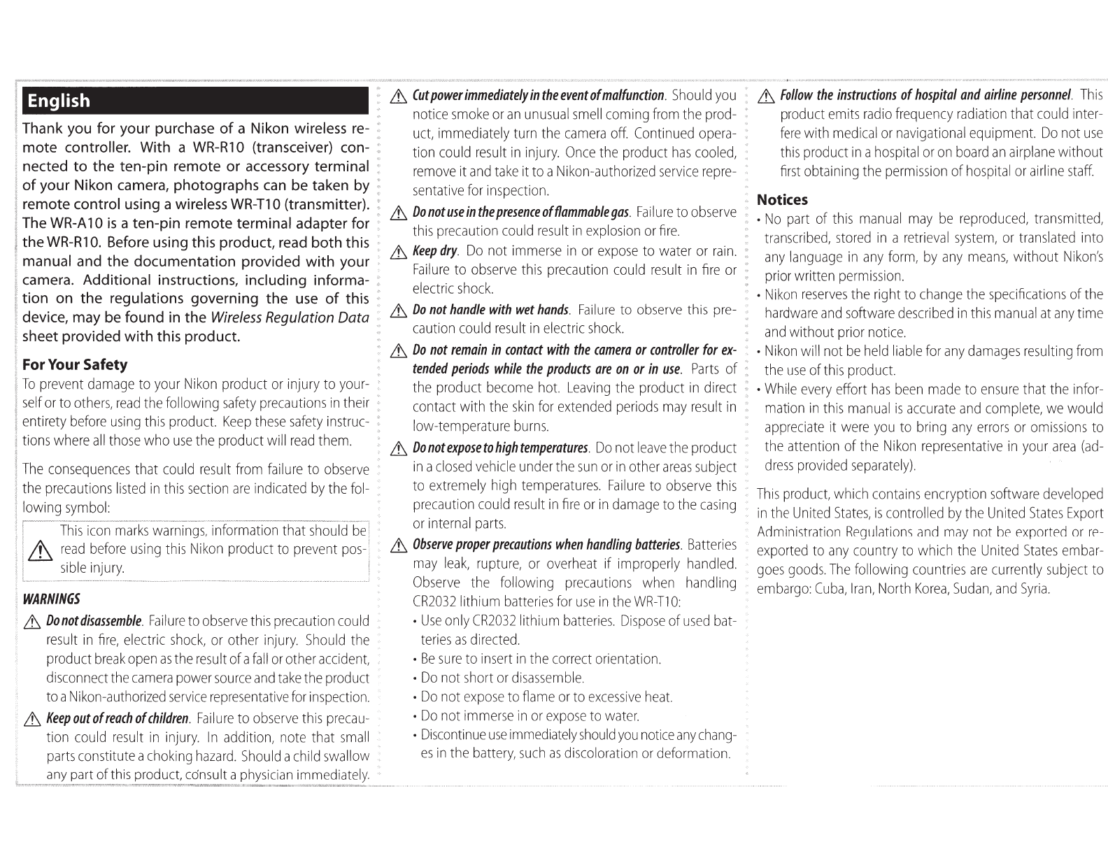
SURRiied Accessories
The
product
is
sold
in
the
sets
below.
This
manual
as-
sumes
you
have
a
WR-R1
0,
WR-T1
0,
and
WR-A
10.
O
Case
0
Warranty
WR-R
10 0
Strap
for
WR-R1
0 0
Strap
for
WR-T1
0
~::A~h
o
CR2032
3vlithium battery'
0
User's
Manual
(this
manual)
WR-R
10 0
Case
0
Warranty
0
Strap
for
WR-R1
0 0
User's
Manual
(this
manual)
0
Strap
for
WR-T1
0 0
Warranty
WR-T10
O
CR2032
3Vlithium battery*
O
User's
Manual
(this
manual)
WR-A10
0
User's
Manual
(this
manual)
*Remove
insulating
sheet
from
WR-T10
before
first
use.
Parts
of
the
Controller
(Figure 1
),
_____
_
G)
Red
LED
®Channel
selector
@Green
LED
@
Pairing
button
®
Strap
eyelet
®Shutter-release button 0
Fn
button
@
Strap
eyelet
®
Red
LED
@)Channel
selector
@
Pairing
button
~Hi~Jg
@
Release
button
@Mounting
mark
····
B
The
WR-Rl
0
Strap
. Attach the
WR-R1
0 to the camera strap
as
shown
in
Figure 2 to prevent the
WR-R1
0 being lost or dropped.
·····
····
B
Replacing
CR2032
3V
Lithium
Batteries
{Figure
3)
·····
Replace
the battery when the
LED
for the
WR-T1
0 starts
····
to dim. Insert a fingernail behind the battery-chamber
latch and open the battery chamber (G)).
Ensure
that
·····
the battery
is
inserted
in
the correct orientation (@)).
Using
the
WR-R1 0 (Transceiver),
______
_
Cameras
with
accessory
terminals
(Figure
4-a):
Connect the
WR-R1
0
as
shown
by
the
marks
on
the
camera
(_.)
and
WR-R1
0
('~).
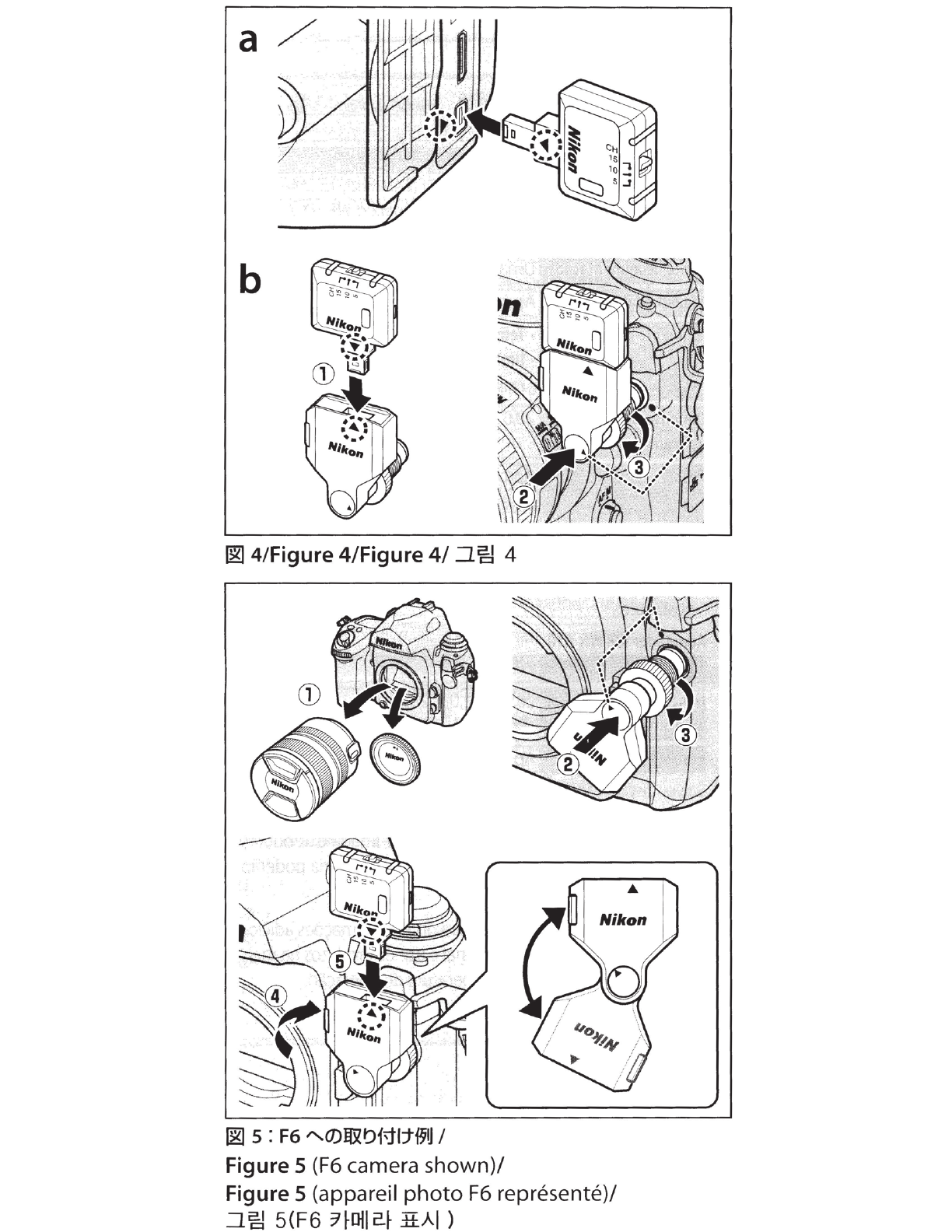
Digital
cameras
with
ten-pin
remote
terminals
(Figure
4-b):
Attach the
WR-A
10
WR
adapter
(G))
as
shown
by
the
marks
on
the adapter
(_.)
and
WR-R1
0
(T)
and
connect the
assembly
to the ten-pin remote terminal
(@),keeping the mounting mark
on
the
WR-A
10
(G))
aligned with
thee
mark
on
the terminal. Tighten the
WR-A
10 locking
screw
(@)).
Film
cameras
with
ten-pin
remote
terminals
(Figure
5):
If the
terminal
is
on
the front ofthe camera, remove the
lens
or
camera body
cap
(G)).
Attach
the
WR-A
10,
keep-
ing
the mounting
mark
(G)) aligned with the mark
on
the terminal
(@).
After
tightening the
WR-A
10
lock-
ing
screw(@)), rotate the
WR-A
10
(@)and
attach the
WR-R1
0
(@)as
shown
by
the
marks
on
the adapter
(_.)and
WR-R1
0
(T).
Note:
Be
sure
the connectors
are
in
the correct orienta-
tion; do not
use
force or insert the connectors at
an
an-
gle. Note that the
WR-R1
0
can
not
be
used
with certain
accessories. Using force or inserting connectors at
an
angle could damage the camera or accessory.
To
remove
the
WR-R10,
reverse
the above
steps.
To
re-
move the
WR-A
10,
press
the
release
button
(Figure
1-@)
while
sliding
the
adapter
from
the
WR-R1
0.
B
The
Fn
Button
When a
WR-R1
0
is
mounted on the cameras below, the
·
Fn
button on the
WR-T1
0 performs the function current-
ly
assigned to the
camera
Fn
button.
See
the camera
manual for details.
·
04
· D800/800E
Using
the
WR-T1 0 (Transmitter),
______
_
The
shutter-release button
on
the
WR-T1
0 performs
the
same
functions
as
the
camera
shutter-release
button whether
pressed
halfway
or
all
the
way
down.
See
the
camera
manual
for
details.
B
Channel
Selection
and
Pairing
Ifthe camera
fails
to respond to the shutter-release but-
ton on the
WR-T1
0,
re-establish the link between the
WR-T1
0 and the receiver
by
matching channels and
pairing the devices
as
described below.
1
Set
the
units
to
the
same
channel.
Set
the channel selectors on
both units
to
the
same
channel
(5,
1
0,
or
15).
Devices on differ-
ent channels
can
not
be
paired,
while paired devices
can
only
be
used
together when both
are
set
to the same channel.
2
Pair
the
devices.
After turning the camera on,
place the
two
devices
close
together and
press
the pairing
buttons
on
both units simultane-
ously.
Keep
the buttons
pressed
until the
red
and green
LEOs
on the
WR-R1
0 flash on
and
off
in
sequence, indicating that pairing
is
complete.
To
erase
pairing data, turn the camera on and keep the
WR-R1
0 pairing button
pressed
for about 3 seconds until
the green
LED
flashes rapidly, and then quickly
press
the
pairing button twice before the green
LED
stops flash-
ing. The green and
red
LEOs
will both flash twice simul-
taneously to show that
all
pairing data
has
been
erased.