nilan Comfort 250L-350L User manual

USER MANUAL
Comfort 250L-350L / Comfort 250L-350L Polar
Gateway
CTS400 BY NILAN
Version 1.00 - 02.05.2022
B75 Comfort 250L-350L GB

2
General information
Safety ............................................................................................................................................................................................................3
Power supply .........................................................................................................................................................................................3
Introduction ..................................................................................................................................................................................................3
Documentation ......................................................................................................................................................................................3
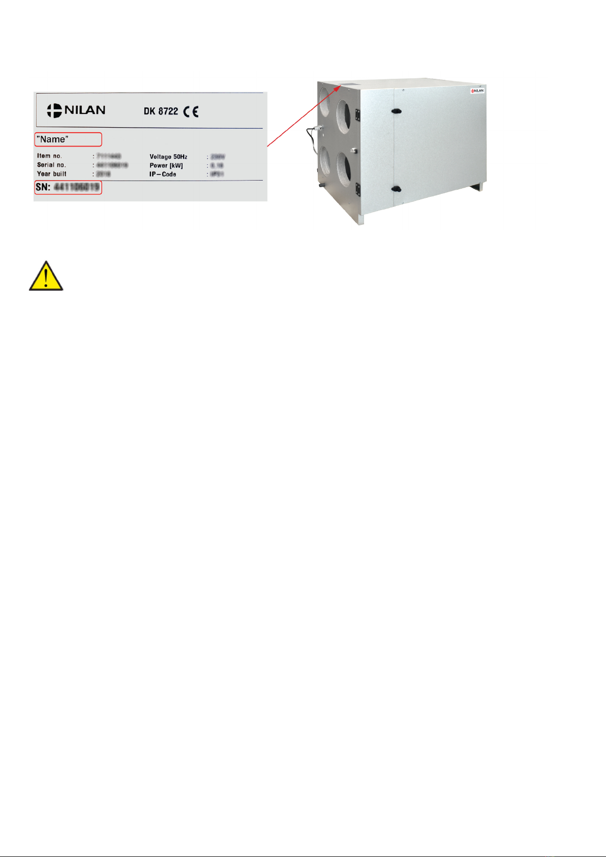
Data plate ...............................................................................................................................................................................................4
App option
Nilan User App ..............................................................................................................................................................................................5
Introduction ...........................................................................................................................................................................................5
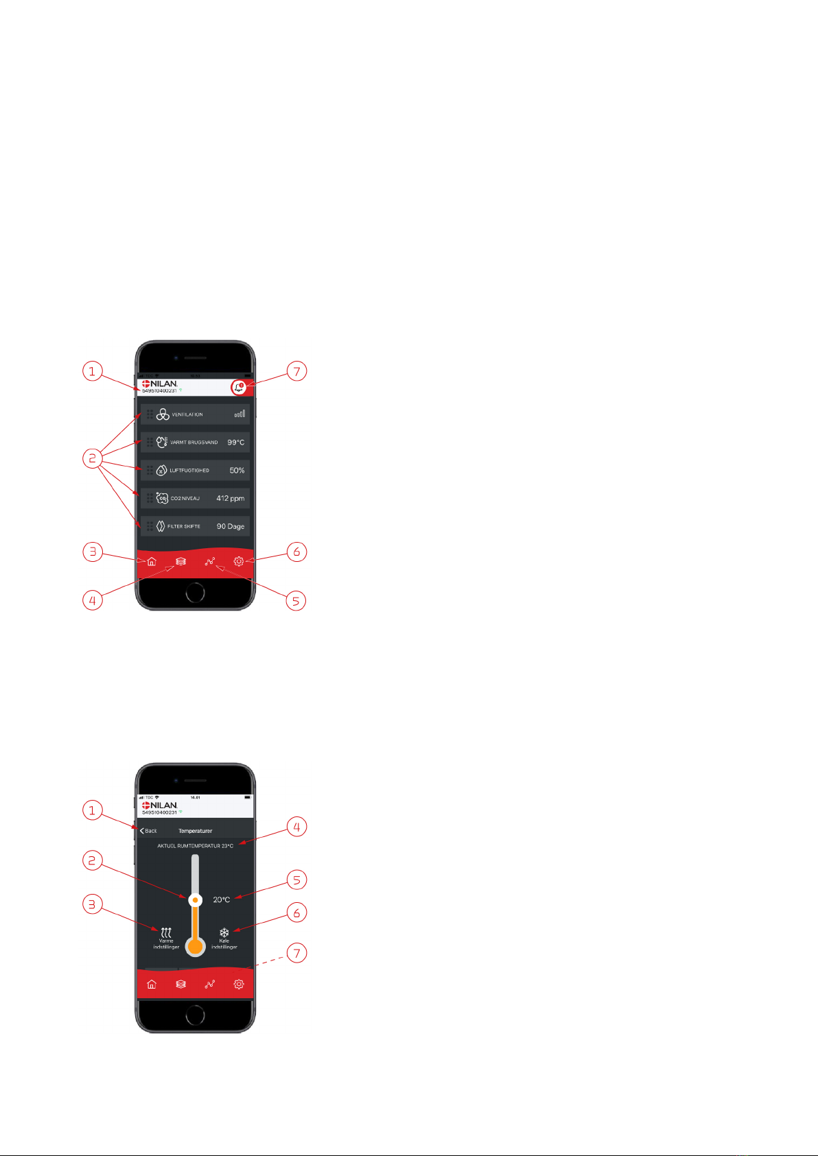
Explanation of main screen items ......................................................................................................................................................5
Temperature ..........................................................................................................................................................................................5
Ventilation ..............................................................................................................................................................................................6
Domestic hot water ..............................................................................................................................................................................6
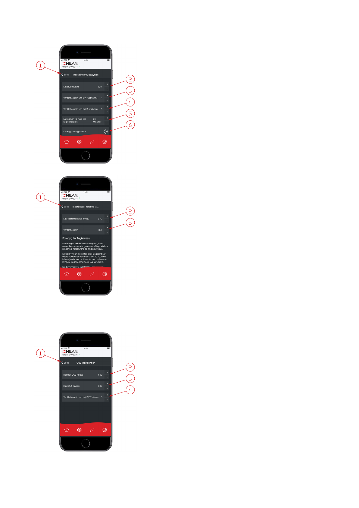
Air humidity ...........................................................................................................................................................................................7
CO2 settings ...........................................................................................................................................................................................7
Filter replacement ................................................................................................................................................................................8
Show data ...............................................................................................................................................................................................8
Trend curve ............................................................................................................................................................................................8
Control panel
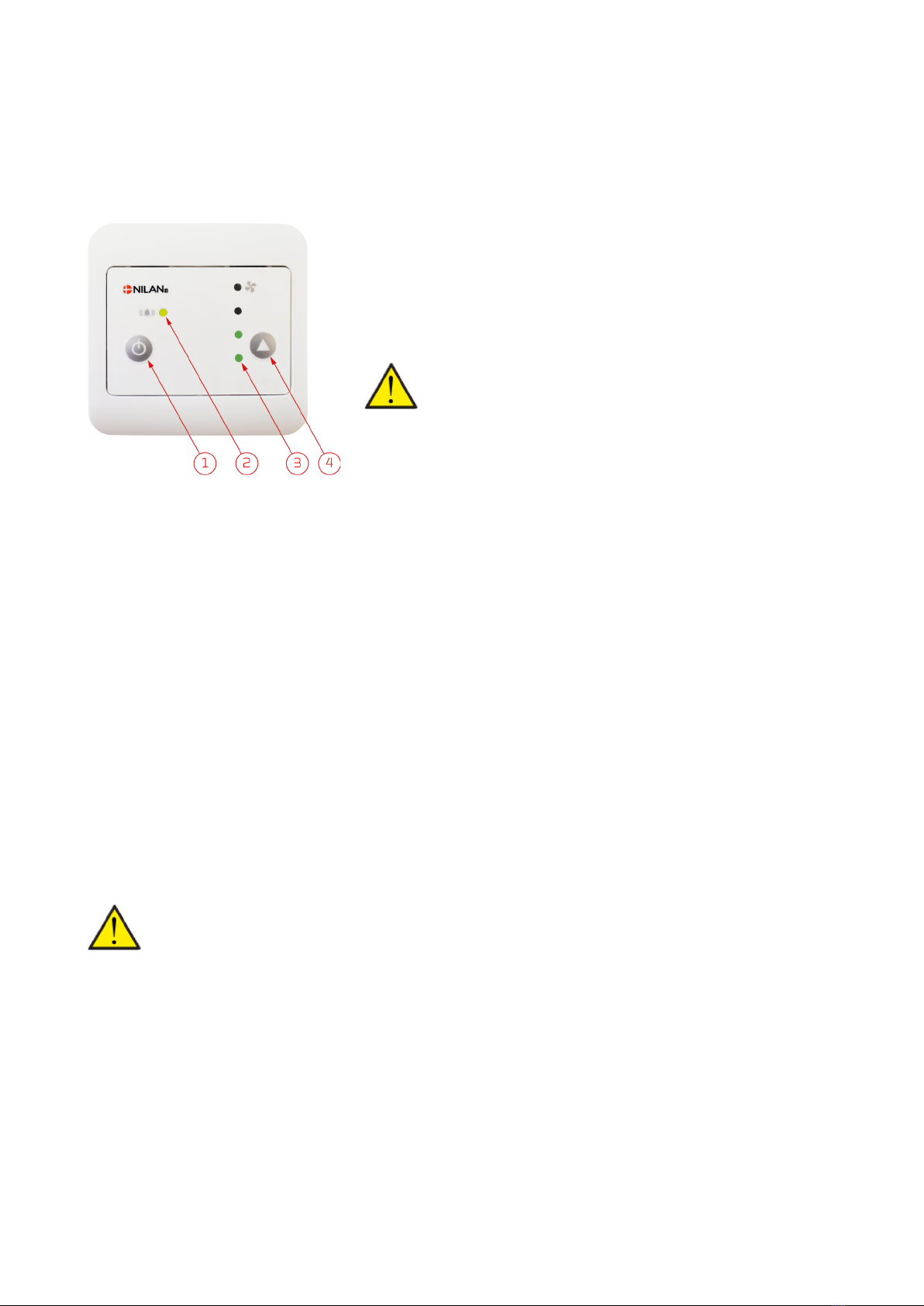
Control panel functions ..............................................................................................................................................................................9
Functional overview .............................................................................................................................................................................9
Fan speed level ......................................................................................................................................................................................9
Warnings and alarms ......................................................................................................................................................................... 10
Damper test ........................................................................................................................................................................................ 11
Control panel locked .......................................................................................................................................................................... 11
Service and maintenance
Generally ............................................................................................................................................................................................. 12
Regular maintenance ............................................................................................................................................................................... 12
Filters ................................................................................................................................................................................................... 12
Illustration of filter change ............................................................................................................................................................... 13
Annual maintenance ................................................................................................................................................................................ 14
General cleaning ................................................................................................................................................................................. 14
Water trap ........................................................................................................................................................................................... 14
Heat exchanger .................................................................................................................................................................................. 15
Check air intake and discharge ........................................................................................................................................................ 15
Check ventilation ducts .................................................................................................................................................................... 15
Product data
EU/EC Declaration of Conformity ................................................................................................................................................... 16
Ecodesign data Comfort 250L ......................................................................................................................................................... 17
Ecodesign data Comfort 350L ......................................................................................................................................................... 18
............................................................................................................................................................................................................... 18
Disposal
The environment - part of the solution ................................................................................................................................................ 19
Ventilation unit ................................................................................................................................................................................... 19

3
General information
Safety
Power supply
Introduction
Documentation
The following documents will be supplied with the unit:
• Quick guide
• Wiring diagram
In the Quick guide you will find important information regarding installation and start-up of the unit. If you require further information
regarding, for instance, installation of accessories or additional settings in the software, or if you need an extended user manual, the
following documents can be downloaded from the Nilan website:
• Installation instructions
• Software instructions
• User Manual
• Wiring diagram
The instructions can be downloaded from www.nilan.dk.
If you have questions regarding installation and operation of the unit after having read the instructions, please contact your nearest
Nilan dealer. A list of Nilan dealers is available on www.nilan.dk.
From factory, the unit has been tested and is ready for operation.
CAUTION
Always disconnect the power supply to the unit if an error occurs that cannot be rectified via the control panel.
CAUTION
If an error occurs on electrically conductive parts of the unit, alway contact an authorised electrician to rectify the error.
CAUTION
Always disconnect the power to supply to the unit before opening the unit doors, for instance for installation, inspection,
cleaning and filter change.
ATTENTION
The unit must be started up immediately after installation and connection to the duct system.
When the ventilation unit is not in operation, humidity from the rooms will enter the duct system and create condensate
water that can run out of the valves and cause damage to floors and furniture. Condensation may also form in the ven-
tilation unit, which can damage its electronics and fans.

4
Data plate
Nilan’s data plate is situated on the top left of the unit.
ATTENTION
When contacting Nilan with questions about the product, it is important to have the unit name and serial no. (SN) ready.
From this information, the service department can find all information about the unit in question and thus help with
information and answer questions about what the unit consists of/contains, and what software is used.
The type of the ventilation unit can also be found in the user panel menu under “Show data”.

5
App option
Nilan User App
Introduction
The following instructions are general and apply to all Nilan ventilation units. Some of the shown functions and settings may therefore
not exist on your ventilation unit. The user settings that are applicable to exactly your ventilation unit will more or less correspond to
those displayed in the Nilan User APP on your phone.
If you require a detailed description of individual functions and settings, you can download the software instructions for your ventila-
tion unit from our website.
Explanation of main screen items
Temperature
1. On the main screen under the Nilan logo, you will see the number of the con-
nected Gateway.
Under settings, you can name the ventilation unit e.g. Home or Holiday home.
The name will then be displayed instead.
If you have more than one ventilation unit connected to the APP, you will be able
to see to which unit the shown data apply.
Next to the number is a WiFi icon that is green when there is connection to the
unit, and red if the connection is interrupted.
2. Here you can see the items that are relevant to your ventilation unit. If there
are too many items to fit the screen simultaneously, the rest will be below the
displayed items. You can access these by using your finger to scroll up.
If you press one of the items on the screen briefly, a settings menu will appear.
3. Shortcut key to return to main screen.
4. If you press this icon, you will see a list of all current and relevant data.
5. If you press this icon, you will get to a page where you can see a trend curve for
relevant data.
6. Pressing this icon will take you to settings where you will be able to add more
ventilation units.
7. The alarm icon will be displayed if an alarm is triggered on the unit. By pressing
the icon, you will get an outline of the most recent alarms.
If more ventilation units are connected to the same APP, you will have to go into
settings and select unit in order to see to which unit the alarm applies.
1. Press “back” to return to the previous page.
2. You can set the room temperature by scrolling up or down with your finger on
the icon. When the ventilation unit is operating in heating mode, the thermom-
eter is red. In cooling mode it is blue, and during neutral operation orange.
3. The icon for heating settings may be displayed if you have installed an after-
heating element. Press this icon to access heating settings.
4. Here you can see the current room temperature.
5. Here you can see the desired room temperature.
6. The cooling icon will be displayed if the unit has active cooling via a heat pump.
Press this icon to access the cooling settings.
7. If you scroll up the items with your finger, a menu appears where you can select
from the options AUTO, HEAT and COOL.

6
Ventilation
Domestic hot water
1. Press “back” to return to the previous page.
2. Here you can set the fan speed level you want. The fan speed level that you
have selected may differ from the one displayed on the main screen. This is
because the unit is able to override the set fan speed level, e.g. at high/low
humidity.
1. Press “back” to return to the previous page.
2. If you scroll down with your finger, you can read off the current temperature of
the hot water.
3. You can set the domestic hot water by scrolling up or down with your finger on
the icon. It is indicated under the thermometer when the unit is producing
domestic hot water. The colour inside the thermometer changes in accordance
with the temperature. A temperature >40°C is red, 30-40°C is orange, and
<30°C is blue. Then you can see whether there is enough hot water for a bath.
4. Here you can see the current setting of the hot water temperature.
5. Press this icon to access more settings.
6. Press here to deactivate the production of hot water. You can reactivate the
hot water production by using your finger to scroll up the thermometer and
select the desired water temperature.
The settings icon (5) gives you access to settings related to supplementary electric
heating and anti-legionella measures.
1. Press “back” to return to the previous page.
2. Here you can choose at what temperature the supplementary electric heating
should be activated in order to help heat the domestic hot water.
3. Here you can deactivate the supplementary electric heating.
4. Here you can turn off the anti-legionella treatment. You can also set a particu-
lar day during the week for anti-legionella treatment.

7
Air humidity
CO2 settings
1. Press “back” to return to the previous page.
2. Here you can set the value for low level of humidity between 15– 45%.
3. Here you can set the fan speed level for low humidity between level 1 – 3. You
can also deactivate the function.
4. Here you can set the fan speed level for high humidity between level 2 – 4. You
can also deactivate the function.
5. Here you can set the maximum time at high humidity.
6. Press this icon to access more settings.
1. Press “back” to return to the previous page.
2. Here you can set the temperature to prevent low outdoor temperature
between -20 – +10°.
3. Here you can set the fan speed level to prevent low humidity between level 1–
3. You can also deactivate the function.
1. Press “back” to return to the previous page.
2. Here you can set the value for normal CO2level between 400 - 700.
3. Here you can set the value for high CO2level between 650 - 2500.
4. Here you can set the fan speed level between level 2 - 4. You can also deacti-
vate the function.

8
Filter replacement
Show data
Trend curve
1. Press “back” to return to the previous page.
2. Here you can set the amount of days between filter replacements.
3. Here you can reset the alarm for filter replacement.
4. Here you can turn off the ventilation unit before filter replacement and turn
the unit on again afterwards.
ATTENTION
Remember never to leave the unit off for a long period of time as con-
densate water may form in the unit and duct system and subsequently
cause damage.
You can read off current operational data for the ventilation unit. This will allow you
to check that the unit operates satisfactorily and to identify the cause of potential
alarms.
It is possible to see a Trend curve on various parameters - depending on
which ventilation unit you have.

9
Control panel
Control panel functions
Functional overview
Fan speed level
Level 1 can be used if you are going to be away for a while, e.g. on holiday for a couple of weeks.
NB: When the unit is operating at low air humidity level, it can be set to operate at fan speed level 1.
Level 2 is for standard operation. The air volume at level 2 is the standard air volume for which the dwelling has been balanced.
NB: The automatic humidity control system alters the function of the unit to run high or low flow ventilation as required.
Level 3 can be used if you have visitors or if, for instance, you have candles burning in the dwelling.
NB: Remember to reduce the fan speed to level 2 once your visitors have left.
Level 4 can be used if, for instance, you are having a party and a large crowd of people are gathered in the dwelling. The unit can also
be set at high humidity level.
NB: This level is also used during cooker hood operation if the cooker hood is connected to the ventilation unit.
If an alarm is triggered in the ventilation unit, the yellow LED will flash. Alarms are divided into 3 categories: Information, warning and
critical alarm.
The following functions are available with the CTS 400 panel:
1. Power on and off button
2. Yellow LED light: Constantly flashing or lit by warnings or alarms
3. Green LED light: The number of lit LED lights indicates the desired fan speed level
4. Switching the fan speed level from 1-4 is done by pressing the arrow, after fan
speed level 4 fan speed level 1 appears again.
ATTENTION
When the unit is overridden by user selection, humidity, defrost, etc., the
desired fan speed level will be lit green, but the current fan speed level will
flash. By pressing the arrow, the unit will go to the desired fan speed level -
until the next event.
ATTENTION
Do not turn off the unit unless, for instance, an emergency notification asks residents to stay indoors, close windows and
doors, and turn off ventilation units.
If the unit is off for long periods of time, dampness in the ducts can cause condensation and subsequently mould growth.

10
Warnings and alarms
If an alarm is triggered in the ventilation unit, the yellow LED will flash. Alarms are divided into 3 categories: Information, warning and
critical alarm.
INFO
The alarm displays a piece of information that needs your attention, e.g. that filters need replacing.
The ventilation unit remains in operation.
The yellow LED stays on:
Filters need replacing.
Replace filters, clean the unit and reset the alarm.
Resetting the alarm:
Press the On/Off button and the button with the arrow at the same time and hold for 10 seconds.
ATTENTION
The alarm displays a warning that needs your attention. The ventilation unit continues to operate, but in emergency
mode.
Briefly, press the On/Off button and the button with the arrow simultaneously. One of the green diodes will flash and dis-
play the following error types.
The yellow diode and the first green diode are flashing:
The temperature sensor has either short-circuited or been disconnected.
Register the error and contact service. Reset the alarm once the error has been rectified.
Resetting the alarm:
Press the On/Off button and the button with the arrow at the same time and hold for 10 seconds.
The yellow diode and the second green diode are flashing:
The humidity sensor or the CO2 sensor has either short-circuited or been disconnected.
Register the error and contact service. Reset the alarm once the error has been rectified.
Resetting the alarm:
Press the On/Off button and the button with the arrow at the same time and hold for 10 seconds.
The yellow diode and the third green diode are flashing:
The thermostat in the after-heating has short-circuited or been disconnected.
Make a note of which sensor is faulty and contact service. Reset the alarm once the error has been
rectified.
Resetting the alarm:
Press the On/Off button and the button with the arrow at the same time and hold for 10 seconds.

11
Damper test
If a fire automation system has been connected and it has been activated in PC Tool, it will run a damper test. The damper test lasts
approx. 3 minutes and it is carried out every 7/ 14 or 28 days (set in the Software). The test will also run every time the unit starts up
after having been turned off. When the test has been completed, the unit will continue in the defined settings.
Control panel locked
You can lock the control panel in two different ways: The On/Off button and/or the button with the arrow.
WARNING
The alarm displays a critical alarm that needs your attention.
The ventilation unit has stopped.
The yellow diode and the first two green diodes are flashing:
The fire alarm has been activated.
If there is no fire, contact service. Reset the alarm once the error has been rectified.
Resetting the alarm:
Press the On/Off button and the button with the arrow at the same time and hold for 10 seconds.
The yellow diode and the upper two green diodes are flashing:
Frost in the water after-heating element (if installed)
Contact service. Reset the alarm once the error has been rectified.
Resetting the alarm:
Press the On/Off button and the button with the arrow at the same time and hold for 10 seconds.
The 4 green LED lights range from 1-4:
A damper test is carried out that take approx. 3 min .
Resetting the alarm:
The alarm stops automatically when the test has finished, and the control panel will once again dis-
play the current fan speed level.
All LEDs flash temporarily:
If all the LEDs flash temporarily when you use the panel, the panel has been locked.
Contact the caretaker or service provider if that happens.
Resetting alarms:
You can still reset alarms.
Press the On/Off button and the button with the arrow at the same time and hold for 10 seconds

12
Service and maintenance
Generally
A ventilation unit from Nilan can last for many years if it is properly serviced and maintained. Ventilation units are often hidden away,
and they are therefore rarely given attention in everyday life. But just as you maintain your car, your ventilation unit will need servic-
ing regularly to keep it functioning properly.
If appropriate service and maintenance are not carried out, the ventilation unit may get damaged. It can also result in increased energy
consumption and a poorer indoor climate. Less air will run through the unit even if the fans are running faster. But the ventilation unit
does not operate well with dirty filters, a clogged up heat exchanger and dusty fans.
You can set an alarm in your calendar on your phone that will notify you when your ventilation unit is due a service. Alternatively, you
can make a service appointment with your local Nilan dealer or service company.
Regular maintenance
Filters
The primary purpose of the filters is to protect the ventilation unit and especially the heat exchanger and the fans that could otherwise
become damaged by dust and dirt.
Dirty filters result in a poorer indoor climate and a higher energy consumption. Dirty filters must therefore be replaced. Dirty filters
can also affect the humidity control system in the ventilation unit so it no longer works as intended.
The standard filters in the ventilation unit are ISO Coarse > 65% (G4). If you install a pollen filter ISO ePM1 50-65% (F7), you will not
need to replace the pollen filter as often, as its filter area is larger. It may then only be necessary to replace the pollen filter every sec-
ond or third time, depending on its condition.

13
Illustration of filter change
1.Before opening the door, switch off the unit on the con-
trol panel under OPERATION.
2. Loosen the brackets in the door and tilt the left door to
the side.
3. Remove the two filters from the unit. 4. It is advisable that you vacuum the filter chambers for
potential dirt and dust.
5. Remove the filter sheet from the filter frame. 6. Keeping the smooth side facing downwards, place the
new filter sheet in the filter frame.
7. Press the filter sheet firmly in place and carefully push
it to the sides of the filter frame.
Place the filter in the unit with the filter sheet facing
upwards.
8. Turn on the unit and press the ALARM icon to reset the
warning.

14
Annual maintenance
General cleaning
The ventilation unit should be cleaned on the inside once a year. Dust may escape through the filters and potentially mix with moisture
from the extract air.
You may want to vacuum the ventilation unit before you clean it on the inside using a slightly damp cloth. Be careful around potentially
sharp edges. Be careful not to get water into the electrical control system.
The ventilation unit should also be cleaned on the outside using a slightly damp cloth and a mild detergent.
Valves in the ceiling
Over time a ring may develop around the inlet valves. This is a natural occurrence caused by dust in the air in the room. It is not due to
defective filters or filters not being replaced.
Since painted ceilings are only rarely washable, we recommend that you vacuum the area around the valves before wiping them with
a slightly damp cloth.
It is a good idea to detach the valves and then clean them when necessary. The valves have been set by the installer at a specific air
volume, so it is important that you do not turn them, as this will change the setting and unbalance the ventilation system.
Water trap
During cold periods when the ventilation unit operates with high efficiency heat recovery, the extract air creates condensation. It is
important that this water can drain freely from the condensate tray. If it cannot drain properly, it will eventually leak out of the unit
door and, potentially, cause water damage.
Water trap with ball
1. Pour water into the condensate tray and check that it drains away
2. If the water drains away, everything is in order
3. If the water does not drain away, you should check the water trap and the drain to locate any blockages
Water trap without ball
1. Pour water into the condensate tray
2. Close the door of the ventilation unit
3. Start the ventilation unit and let it run for 10 minutes
4. Open the door of the ventilation unit and check that the water has drained away and that it has not run back into the condensate
tray
5. If the water has drained away, everything is in order
6. If the water has not drained away, you should check the water trap and the drain to locate any blockages
WARNING
Stop the ventilation unit on the control panel and switch off the power supply for the ventilation unit before you open
the front door to the unit.
ATTENTION
If you have not installed a water trap with ball, you must check the condensate drain every autumn before the weather
turns cold. (Condensation typically forms when the outdoor temperature < 10°C)

15
Heat exchanger
The counterflow heat exchanger is a central part of the ventilation unit. It heats up the cold outdoor air with energy from the warm ex-
tract air. To maintain a high level of heat recovery, it is important that the heat exchanger is not clogged with dirt.
Experience indicates that it should not be necessary to lift out and clean the heat exchanger every year. However, if it appears to be
dirty, you should lift it out and clean it.
The easiest way to clean the counterflow heat exchanger is in the shower. Use lukewarm water and rinse it well from both sides. Allow
it to drip off before remounting it in the ventilation unit.
Check air intake and discharge
It is important for operation of the unit that air can freely move through the air intake and discharge.
If roof stacks have been fitted to the air intake and discharge, check that they are not blocked with birds' nests, leaves or other dirt
which can hamper air passage.
If, instead of roof stacks, grilles have been mounted in facades or eaves, check that they are not clogged with leaves or dirt. Grilles are
particularly likely to become clogged.
Check ventilation ducts
It is important for operation of the unit that there is free air passage through the ventilation ducts.
After some years of operation, dirt will attach itself to ventilation ducts or tubes, and accumulations may lead to higher pressure drop
in the ducts, leading to higher power consumption. It is therefore important to clean out the ducts when too much dirt has collected.
After attending to the inlet and outlet valves, it will be advisable to have them adjusted again, to ensure optimum operation of the ven-
tilation system.
However, it will not be necessary to clean ducts more than every few years.

16
Product data
EU/EC Declaration of Conformity

17
Ecodesign data Comfort 250L
* Specific energy consumption
** Annual heating saved
SEC* average climate -41,6Wh/(m2.a)
SEC* cold climate -80,4 kWh/(m2.a)
SEC* warm climate -16,8 kWh/(m2.a)
SEC*-Class A
Type Two-way ventilation unit for residential
Type of drive Variable speed drive
Type of heat recovery system Recuperative (counterflow heat exchanger)
Thermal efficiency of heat recovery 90%
Maximum flow rate 250m3/h (100 Pa)
Electric power input of fan drive, including any motor control
equipment at maximum flow rate
70,5W
Sound power level (LWA) 41 dB(A)
Reference flow rate 0.049 m3/s (175 m3/h)
Reference pressure difference 50 Pa
SPI 0.18 W/(m3/h)
Central demand control 0.85
Maximum internal leakage 0,4%
Maximum external leakage 0,2%
Visual filter warning An alarm on the user panel appears when filters need changing.
To maintain the performance and energy efficiency of the unit
it is very important to change filters regularly.
Disassembly instructions www.nilan.dk
AEC - annual electricity consumption 208 kWh/year (100 m2)
AHS** average climate 4616 kWh (100 m2)
AHS** cold climate 9030 kWh (100 m2)
AHS** warm climate 2087 kWh (100 m2)

18
Ecodesign data Comfort 350L
* Specific energy consumption
** Annual heating saved
SEC* average climate -40,0kWh/(m2.a)
SEC* cold climate -77,6 kWh/(m2.a)
SEC* warm climate -15,8 kWh/(m2.a)
SEC*-Class A
Typology Two-way ventilation unit for residential
Type of drive Variable speed drive
Type of heat recovery system Recuperative (counterflow heat exchanger)
Thermal efficiency of heat recovery 85 %
Maximum flow rate 372 m3/h (100 Pa)
Electric power input of fan drive, including any motor control
equipment at maximum flow rate
169 W
Sound power level (LWA) 47 dB(A)
Reference flow rate 0.073 m3/s (262 m3/h)
Reference pressure difference 50 Pa
SPI 0.20 W/(m3/h)
Central demand control 0.85
Maximum internal leakage rates 0.4%
Maximum external leakage rates 0.2%
Visual filter warning An alarm on the user panel appears when filters need changing.
To maintain the performance and energy efficiency of the unit
it is very important to change filters regularly.
Disassembly instructions www.nilan.dk
AEC - annual electricity consumption 226 kWh/year (100 m2)
AHS** average climate 4494 kWh (100 m2)
AHS** cold climate 8792 kWh (100 m2)
AHS** warm climate 2032 kWh (100 m2)

19
Disposal
The environment - part of the solution
At Nilan A/S we recognize our responsibility in minimizing the environmental impact of our products. We consider the impact on the
environment in all aspects of production, operation and subsequent disposal. We recognize our responsibility in minimizing consump-
tion of resources. We work continuously to improve our products and the production process in order to limit our impact on the envi-
ronment.
Ventilation unit
Nilan units consist mainly of recyclable materials. They must, therefore, not be mixed with household waste, but
must be delivered to your local recycling center for disposal.
The only tools required are Torx20 and Torx25 screwdrivers and per-
haps some side-cutting pliers for cutting wires.
1. Remove the fans and dispose of them as electronic waste.
2. Demount the orange bypass motor and dispose of it as electronic
waste.
3. The circuit board and the electronics are situated behind the green
counterflow heat exchanger. These too should be disposed of as
electronic waste

Nilan A/S disclaims all liability for potential errors and omissions in printed instructions - or for loss or damages arising from published materials, whether these are due to errors or
inexpediency in the publications or they have other causes. Without prior notice Nilan A/S reserves the right to make changes to the products and instructions. All trademarks belong to
Nilan A/S. All rights reserved.
Nilan A/S
Nilanvej 2
8722 Hedensted
Danmark
Tlf. +45 76 75 25 00
www.nilan.dk
United Kingdom:
S L Services Ltd
The Barn
25 St Leonards Road
Horsham
West Sussex
RH13 6EH
Tel: +44 (0) 14 03 56 30 45
www.slservicesgroup.com
Ireland:
Nilan Ireland
Ballylahive, Abbeydorney
Tel: +353 (0) 87 97 98 361
www.nilanireland.ei
This manual suits for next models
1
Table of contents
Other nilan Gateway manuals