Wolf DHW Series User manual

1
Art.-Nr. 30 44 704 04/05
MontageanleitungAnschlußset
Speicher-Wassererwärmer Fremdfabrikat
Seite 2
D
DHW cylinders connection set installation instructions
for makes other than Wolf GB-E
Page 3
GB
Istruzioni di montaggio set di collegamento bollitore ad
accumulo di altro produttore
Pagina 4
I
InstruccionesdeinstalaciónKitdeconexióndelacumulador
indirecto de agua caliente de otros fabricantes
Página 5
E
Instrukcja montażu zestaw podłączeniowy zbiornik i
podgrzewacz wody produkt obcej firmy
Strona 6
PL
Montážní předpis pro soupravu k připojení cizího
zásobníku pro přípravu TUV
Strana 7
CZ
Návod na montáž pre súpravu na pripojenie cudzieho
zásobníka pre prípravu TÚV
Strana 8
SK
Montagevoorschrift aansluitset
voor boiler vreemd fabrikaat
Pagina 9
NL
Bekötőcsomag Szerelési Utasítás SE és SEM használati
melegvíz tárolókhoz.
10. oldal
H
Wolf GmbH · 84048 Mainburg · Postfach 1380 · Telefon 08751/74-0 · Telefax 08751/741600·www.wolf-heiztechnik.de

2
MontageanleitungAnschlußset
Speicher-Wassererwärmer Fremdfabrikat
Installation Heiztherme
Speichervorlauf/Speicherrücklauf
ACHTUNG
Inbetriebnahme
Dreiwege-
Umschaltventil
Heizungsvorlauf
Speichervorlauf
Gaszuleitung
Gasheiztherme
Dreiwege-
Umschaltventil
Heizungsrücklauf
Speicherrücklauf
Heiztherme gemäß Montageanleitung montieren.
- Blindstopfen am Heizungsrücklauf entfernen.
- Bogen am Heizungsvorlauf entfernen.
- Dreiwege-Umschaltventil aus Anschlußset mit beiliegenden Dichtungen am
Heizungsvorlauf montieren.
- Speicherrücklaufrohr an der Gasheiztherme mit Flachdichtung verschrauben.
- Speichervorlaufrohr am Dreiwege-Umschaltventil mit Flachdichtung verschrau-
ben.
- Weitere Verrohrung bauseits.
- Gelben Blindstecker an der Regelung Heiztherme entfernen und das Dreiwege-
Umschaltventil anschließen.
- Blauen Stecker des elektronischen Speicherfühlers mit blauer Buchse der Rege-
lung verbinden.
- Elektronischen Speicherfühler in Tauchhülse des Speichers stecken. (siehe
Anleitung Speicher-Wassererwärmer)
Montage der Klemmringverschraubungen nur unter Verwendung beiligender
Stützhülsen.
Heizungsanlage füllen und sehr sorgfältig entlüften. Während des Füllens das
Dreiwege-Umschaltventil per Handverstellung mehrmals öffnen. Zusätzlich an der
Entlüftungsschraube im Speicherrücklauf der Heiztherme entlüften.
Speicher-Wassererwärmer füllen.
Gerät einschalten und gewünschte Warmwassertemperatur an der Regelung der
Heiztherme einstellen: Stellung 1: 15°C
Stellung 7: 60°C
Stellung 9: ca. 70°C
Zum kurzfristigen Anheben der Warmwassertemperatur über 60°C, Drehknopf
Temperaturwahl Warmwasser ca. 3 mm nach vorne ziehen und nach rechts drehen.
Bogen
Blindstopfen
Wolf GmbH · 84048 Mainburg · Postfach 1380 · Telefon 08751/74-0 · Telefax 08751/741600 · www.wolf-heiztechnik.de

3
Install the wall-mounted boiler in accordance with installation instructions.
- Remove the dummy plug from the heating return.
- Remove the bend from the heating flow.
- Install the three-way changeover valve from the connection set with the
enclosed gaskets to the primary flow.
- Secure the DHW cylinder returned pipe with flat gasket to the gas fired boiler.
- Secure the DHW cylinder flow pipe with flat gasket to the three-way changeover
valve.
- All other pipework on-site. Ensure the system is properly vented.
- Remove the dummy plug from the boiler control unit, and connect the three-way
changeover valve.
- Connect the blue plug of the electronic DHW sensor with the blue socket on the
control unit.
- Insert the electronic DHW sensor into the DHW cylinder sensor well.
Install the compression fittings only with the support sleeves supplied.
Fill the heating system and vent carefully. During the filling process vent the boiler via
the air-vent valves at the DHW cylinder flow and return.
Fill the DHW cylinder.
Switch ON the boiler and select the required DHW temperature at the control unit.
DHW cylinders connection set installation
instructions for makes other than Wolf GB-E
Boiler installation
DHW cylinder flow/return
PLEASENOTE
Initial start-up
Three-way
changeover
valve
Central heating
flow
DHW flow
Gas supply pipe
Gas fired boiler
Three-way
changeover valve
Central heating
return
DHW return
Bend
Primary flow
Dummyplug
Primary return
DHW cylinder
flow vent valve
DHW return
vent valve
DHW return
vent valve
DHW flow
vent valve
Wolf GmbH · 84048 Mainburg · Postfach 1380 · Telephon 08751/74-0 · Telefax 08751/741600 · www.wolf-heiztechnik.de

4
Istruzioni di montaggio set di collegamento
bollitore ad accumulo di altro produttore
Installazione caldaia
Mandata/ritorno bollitore ad
accumulo
ATTENZIONE
Messa in servizio
Valvola
deviatrice
a tre vie
Mandata riscald.
Mandata bollitore
Tubo d'alimentaz. gas
Caldaia murale
a gas
Valvola
deviatrice a
tre vie
Ritorno riscald.
Ritorno bollitore
Montare la caldaia secondo le istruzioni di montaggio in dotazione.
- Togliere il tappo cieco sul ritorno della caldaia.
- Togliere la curva sulla mandata caldaia.
- Montare la valvola deviatrice a tre vie dal kit di collegamento sulla mandata
caldaia, utilizzando le guarnizioni in dotazione.
- Collegare il tubo ritorno bollitore con la caldaia utilizzando le guarnizioni piatte.
- Collegare il tubo mandata bollitore con la caldaia utilizzando le guarnizoni piatte
- Raccordi aggiuntivi lato costruttivo.
- Togliore la spina cieca dalla regolazione caldaia e collegare la valvola deviatrice
a tre vie.
- Allacciare la spina blu della sonda elettronica del bollitore con la presa blu della
regolazione.
- Inserire la sonda elettronica del bollitore nel pozzetto ad immersione del bollitore
(vedi le istruzioni del bollitore ad accumulo).
Eseguireil montaggio di tutti i raccordiad anello di fissaggio utilizzandoi manicotti
di sostegno in dotazione.
Caricare e disaerare accuratamente l'impianto di riscaldamento. Durante il
riempimento, aprire ripetutamente a mano la valvola deviatrice a tre vie. Disaerare
inoltre sulla vite di sfiato nel ritorno bollitore della caldaia murale a gas.
Caricare il bollitore ad accumulo.
Accendere la caldaia ed impostare la temperatura dell'acqua calda sulla regolazione
della caldaia murale a gas: Posizione 1: 15°C
Posizione 7: 60°C
Posizione 9: ca. 70°C
Curva
Tappo cieco
Wolf Caldaie Italia S.r.l. · Via 25 Aprile, 17 · I-20097 S. Donato Milanese (MI) · Tel. +39-02-5161641

5
Instalar la caldera según las instrucciones de instalación
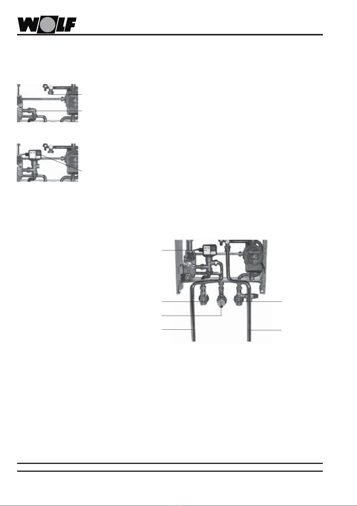
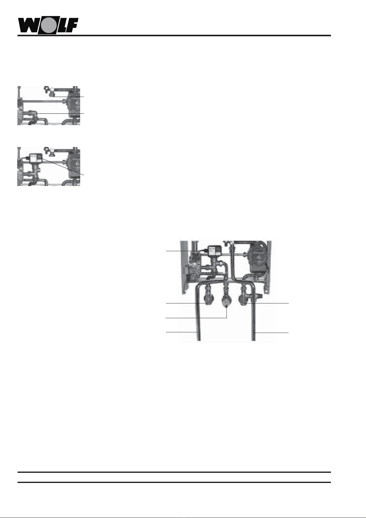
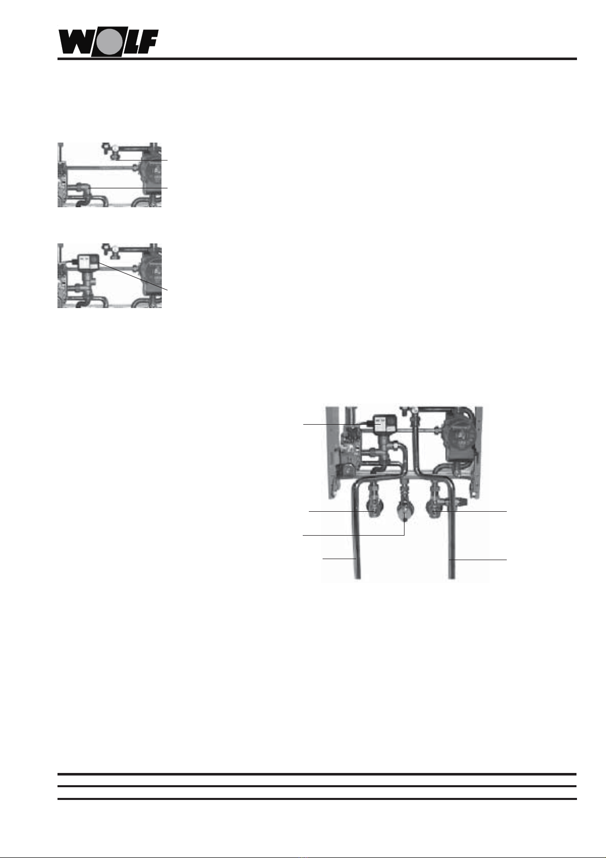
- Quitar el tapón ciego del retorno de calefacción
- Quitar el codo de la ida de calefacción
- Montar la válvula conmutadora de tres vías del kit de instalación en la ida de
calefacción con las juntas que se suministran.
- Atornillar el tubo de retorno del acumulador a la caldera con junta plana.
- Atornillar el tubo de ida del acumulador a la válvula conmutadora de tres vías con
junta plana.
- Otras tuberías del lado de la vivienda,
- Quitar el falso conector de la caja de control de la caldera y conectar la válvula
conmutadora de tres vías.
- Unir el conector macho azul del sensor electrónico del acumulador con el conector
hembra de la caja de control de la caldera.
- Introducir el sensor electrónico del acumulador en el casquillo sumergible del
acumulador (ver instrucciones del acumulador indirecto de agua).
Para montar los racores de compresión sólo se utilizarán los casquillos de
empalme que se suministran.
Llenar la instalación de calefacción y proceder a su purga con meticulosidad. Durante
el llenado, abrir varias veces por regulación manual la válvula conmutadora de tres
vías. Purgar además con el tornillo de desaireación existente en el retorno de
acumulador de la caldera.
Llenar el acumulador indirecto de agua.
Encender el aparato y ajustar la temperatura de agua caliente al valor deseado en
el cuadro de control de la caldera: Posición 1: 15 °C
Posición 7: 60 °C
Posición 9: 70 °C aprox.
Para elevar momentáneamente la temperatura del agua caliente por encima de 60°C
en el acumulador, empujar unos 3 mm hacia delante el mando giratorio del selector
de temperatura del agua caliente y girarlo hacia la derecha.
InstruccionesdeinstalaciónKitdeconexióndelacumulador
indirectodeaguacalientedeotrosfabricantes
Instalación de la caldera mural a gas
Puesta en marcha
Wolf Iberica S.A. · Pae Casablanca · C/José Echegaray 4, Edeficio B4, Planta 2 · E-28109 Alcobendas (Madrid) · Tel.: 91-661.18.53 · Fax: 91-661.03.98
Ida del acumulador/retorno del
acumulador
Válvula
conmutadora de
tres vías
Codo
Tapón ciego
ATENCIÓN
Ida de calefacción
Ida del acumulador
Acometida de gas
Caldera mural a
gas
Válvula conmutadora
de tres vías
Retorno de
calefacción
Retorno del
acumulador

6
Termęgrzewczązainstalowaćzgodnie z instrukcjąmontażu.
- Usunąć zaślepkęw termie grzewczej.
- Zamontowaćruręodpływu zbiornika.
- Usunąć łuk w dopływie termy grzewczej.
- Zamontowaćtrójdrożny zawór przełączający.
- Wbudowaćrurędopływowązbiornika.
- Usunąć żółtązaślepkęna regulacji termy grzewczej i przyłączyćtrójdrożny zawór
przełączeniowy.
- Pozostałe orurowanie od strony budowy.
-Połączyćniebieskąwtyczkęelektronicznego czujnika zbiornika z niebieskąpuszką
regulacji.
- Wetknąć elektroniczny czujnik zbiornika w tulejkęzanurzeniowązbiornika. (Patrz
instrukcja do zbiornika i podgrzewacza wody).
Montażzaciskowych złączek rurowych tylko przy zastosowaniu załączonych
tulejek.
Urządzenie grzewcze napełnići bardzo starannie odpowietrzyć. W czasie napełniania
wielokrotnie otwierać, poprzez ręczne przestawienie, trójdrożny zawór przełączeniowy.
Odpowietrzyćdodatkowo na śrubie odpowietrzającej w odpływie zbiornika termy
grzewczej.
Napełnićzbiornik i podgrzewacz wody.
Włączyćurządzenie i na regulacji termy gazowej ustawićżądanątemperaturęwody
ciepłej: pozycja 1: 15°C
pozycja 7: 60°C
pozycja 9: około 70°C
W celu szybkiego podniesienia temperatury wody ciepłej do ponad 60°C należy
pokrętło wybieracza temperatury wody ciepłej pociągnąć około 3 mm do przodu i
obrócićw prawo.
Instrukcja montażu zestaw podłączeniowy zbiornik
i podgrzewacz wody produkt obcej firmy
Instalacja terma grzewcza
Dopływ zbiornika/odpływ zbiornika
UWAGA
Rozruch
dopływ
ogrzewania
dopływ
zbiornika
doprowadzenie
gazu
gazowa terma
grzewcza
trójdrożny
zawór
przełączeniowy
odpływ
ogrzewania
odpływ zbiornika
zaślepka
kolanko/łuk
trójdrożny
zawór
przełączeniowy
Wolf-Technika Grzewcza sp.z.o.o. · Majdan 105 · PL-05-462 Wiązowna · Tel. 022/7890617 · Fax 022/7890864

7
Heiztherme gemäß Montageanleitung montieren.
Pro napojení zásobníku je třeba provést tyto operace :
- sejmout záslepku na odvětvení větve vratné vody v kotli,
- na její místo připojit potrubí vratky zásobníku,
- vymontovat koleno ve větvi náběhové vody v kotli,
- místo kolena osadit třícestný přepínací ventil,
- ke třícestnému ventilu připojit potrubí náběhu zásobníku TUV,
- ze žlutého konektoru na regulační automatice sejmout záslepku shodné barvy a
do konektoru připojit žlutý konektor od třícestného přepínacího ventilu,
- dokončit propojení zásobníku na užitkovou vodu (teplou i studenou),
- vyjmout záslepku z modrého konektoru na regulační automatice a na její místo
zasunout modrý konektor elektronického čidla teploty TUV v zásobníku,
- elektronické čidlo teploty TUV zasunout do měřicí jímky v zásobníku.
Montáž šroubení provádět pouze s použitím přiložených ochranných pouzder.
Napustit topnou soustavu a dokonale ji odvzdušnit. Při plnění je třeba několikrát
otevřít třícestný přepínací ventil pomocí ruěního ovládání. Je třeba odvzdušnit i
potrubí vratky okruhu dobíjení zásobníku TUV pomocí odvzdušňovacího šroubu na
vratné větvi topné vody v kotli.
Naplnit zásobník TUV.
Zapnout kotel a nastavit na regulační automatice požadovanou teplotu TUV
poloha ovládače 1 : 15 °C
poloha ovládače 7 : 60 °C
poloha ovládače 9 : ca 70 °C
Pro krátkodobá zvýšení teploty nad 60 °C je třeba ovladačteploty TUV povytáhnout
asi 3 mm a pak otočit doprava.
Montážní předpis pro soupravu k připojení
cizího zásobníku pro přípravu TUV
Instalace kotle
Náběh a vratka zásobníku
POZOR
Uvedení do provozu
Trojcestný
přepínací ventil
Náběh topné vody
Náběh zásobníku TUV
Připojení plynu
Kotle
Trojcestný
přepínací ventil
Vratka topné
vody
Vratka zásobníku
TUV
Koleno
Záslepka
FLOW CLIMA, s.r.o. · Baarova 2 · 140 00 Praha 4 · Telefon 241 483 130 · Fax 241 483 129
FLOW CLIMA, s.r.o. · Hviezdoslavova 55 · 62700 Brno · Telefon 548 213 005 · Fax 548 213 016

8
Nainštalovaťkotol podľa návodu.
- vyskrutkovaťzaslepovací uzáver na spiatočke v kotle
- na toto miesto pripojiťpotrubie spiatočky od zásobníka
- demontovaťkoleno na výstupe vykurovacej vody v kotle
- namiesto kolena namontovať3-cestný ventil
- pripojiťk 3-cestnému ventilu potrubie prívodu vykurovacej vody do zásobníka
- spojiťžlutý konektor 3-cestného ventila so žltým konektorom vyvedeným z
regulácie kotla, predtým z neho odňaťzaslepovací konektor
- pripojiťzásobník na rozvod pitnej vody
- spojiťmodrý konektor snímača teploty TÚV v zásobníku s modrým konektorom
vyvedeným z regulácie kotla, predtým z neho odňaťzaslepovací konektor
- snímačteploty TÚV zasunúťdo púzdra v zásobníku
Napustiťvykurovaciu sústavu a dôkladne ju odvzdušniť.
Naplniťzásobník TÚV pitnou vodou.
Zapnúťkotol a nastaviťna regulátore požadovanú teplotu TÚV
poloha ovládacieho gombíka 1 : 15 °C
poloha ovládacieho gombíka 7 : 60 °C
poloha ovládacieho gombíka 9 : ca 70 °C
Návod na montáž pre súpravu na pripojenie
cudzieho zásobníka pre prípravu TÚV
Inštalácia kotla
Nábeh a spiatočka vyk.vody
Uvedenie do
prevádzky
3-cestný ventil
výstup vykur. vody
vstup vykur.vody do
zásobníka
pripojenie plynu
3-cestný ventil
spiatočka vykur.
vody
spiatočka vyk.
vody zo
zásobníka
Koleno
Záslepka
FLOW CLIMA SLOVAKIA s.r.o. · Vetvová 6 · 811 02 Bratislava · Telefón 02/62804004 · Fax 02/62804006

9
Gaswandketel volgens installatievoorschriften monteren.
Verwijder de blindstop gaswandketel, kort het boilerretourleidingstuk in en
monteer deze.
Vervang het bochtstuk in de aanvoer van de gaswandketel door het 3-weg-
omschakelventiel, kort het boileraanvoer leidingstuk in en monteer deze.
Sluit het 3-weg-omschakelventiel aan door het verwijderen van de gele ein
stekker van de regeling en deze met de gele kontrastekker te verbinden.
Knelkoppelingen alleen monteren met bijbehorende hulzen !
Installatie vullen en zorgvuldig ontluchten. Gedurende het vullen meermaals het
3-weg-omschakelventiel met de handbediening openen.
Tevens de ontluchtingsschroef van de boilerretour in de gaswandketel openen
Boiler-warmwaterbereider vullen.
Toestel inschakelen en de gewenste warmwatertemperatuur op de regeling
instellen: Stand 1 : 15 °C
Stand 7 : 60 °C
Stand 9 : ca. 70 °C
Voor het kortstondig verhogen van de warmwatertemperatuur boven 60 °C,
draaiknop temperatuurinstelling boilerwater iets uittrekken en naar rechts draaien
Montagevoorschriftaansluitset
voor boiler vreemd fabrikaat
Installatie gaswandketel
Boileraanvoer/-retour
ATTENTIE
In bedrijfname
3-weg-
omschakelventiel
AV
Leidingaansluitstuk
boileraanvoer
Gas
gaswandketel
3-weg-
omschakelventiel
RT
Leidingaansluitstuk
boilerretour
Bochtstuk
Blindstop
Wolf GmbH · 84048 Mainburg · Postfach 1380 · Telefon 08751/74-0 · Telefax 08751/741600 · www.wolf-heiztechnik.de

10
Telepítse a falikazánt a Szerelési Utasításban foglaltak szerint.
- Távolítsa el a zárókupakot a kazán visszatérővezetékéből.
- Távolítsa el a könyökidomot a kazán előremenővezetékéből.
- Építse be a váltószelepet a könyökidom helyére. A szelephez a tömítéseket a
váltószelep dobozában találja meg.
- Csatlakoztassa a tárolófűtés visszatérővezetékét a zárókupak helyére. Ügyeljen
a tömítésre.
- Csatlakoztassa a tárolófűtés előremenővezetékét a váltószelep üres
csonkjára. Ügyeljen a tömítésre.
- A fennmaradó rész szerelését a helyszínen kell megoldani. Figyeljen a
légtelenítés lehetőségére.
- Húzza le a védőkupakot a kazán sárga elektromos csatlakozójáról és
csatlakoztassa a váltószelepet.
- Húzza le a védőkupakot a kazán kék elektromos csatlakozójáról és csatlakoztassa
az elektronikus tárolóérzékelőt.
- Dugja be az elektronikus tárolóérzékelőmásik felét a tároló megfelelőhüvelyébe.
Szorítógyűrűs csatlakozáshoz mindenképpen használja a csőbe feltolható
peremezett merevítőhüvelyeket, amelyeket a gyári készlet tartalmaz.
Töltse fel a fűtési rendszert és gondosan légtelenítse. Használja a tárolófűtés
légtelenítőcsavarjait.
Töltse fel a tárolót.
Kapcsolja be a kazánt és állítsa be a kívánt használati melegvíz hőmérsékletet.
Tekerőgomb 1 -es állás : 15 °C
Tekerőgomb 7 -es állás : 60 °C
Tekerőgomb 9 -es állás : kb. 70 °C.
Ezt használja legionella védelemre. A 9 -es álláshoz a tekerőgombot a 7 -es
állásnál enyhén, kb. 3 mm -rel húzza ki. Csak ezután lehet a gombot 9 -es állásba
tekerni.
Bekötőcsomag SE és SEM használati
melegvíz tárolókhoz.
A kazán felszerelése
Tárolófűtés előremenő, visszatérő
Üzembe helyezés
Váltószelep
Könyökidom
Zárókupak
Wolf Klíma és Fűtéstechnika Kft. · 1097 Budapest · Határ út 50a · Tel. 36 1 357 5984 · Fax 36 1 347 0282
Figyelem !
Fűtési előremenő
szervízcsap
Tárolófűtés előremenő
Gázcsap
Váltószelep
Fűtési
visszatérő
szervízcsap
Tárolófűtés
visszatérő
Légtelenítő
csavar
Légtelenítő
csavar

11

12
Wolf GmbH · 84048 Mainburg · Postfach 1380 · Telefon 08751/74-0 · Telefax 08751/741600·www.wolf-heiztechnik.de
Other manuals for DHW Series
1
Table of contents
Languages:
Other Wolf Heating System manuals
Popular Heating System manuals by other brands

Vent-Axia
Vent-Axia AVHR400 Installation and commissioning instructions

Carrier
Carrier FB4CNF installation instructions

Carrier
Carrier 48DT Series installation instructions

Empire Comfort Systems
Empire Comfort Systems DV-822 installation instructions

Vent-Axia
Vent-Axia 448733 Installation & commissioning

Innova
Innova HRC + manual

Salda
Salda RIS 400 PW EKO 3.0 Technical manual

Energotech
Energotech EnergoStrip EE-3 Series Mounting and installation

Toyotomi
Toyotomi FF-V30 Operation instructions

BLAUBERG
BLAUBERG VENTO Expert A50-1 Pro Operation manual

Aqualine
Aqualine TS-300B Installation and use manual

KORADO
KORADO KORASMART 1300 manual