nilan Comfort 1200 User manual

Version: 10.00, 13-04-2015
Software-version: 2.30
Installation instruction
CTS 602 by Nilan
Comfort 1200
Comfort 5000

Table of contents
Table of contents ............................................................................................................................ 2
Introduction..................................................................................................................................... 3
Power supply.................................................................................................................................. 4
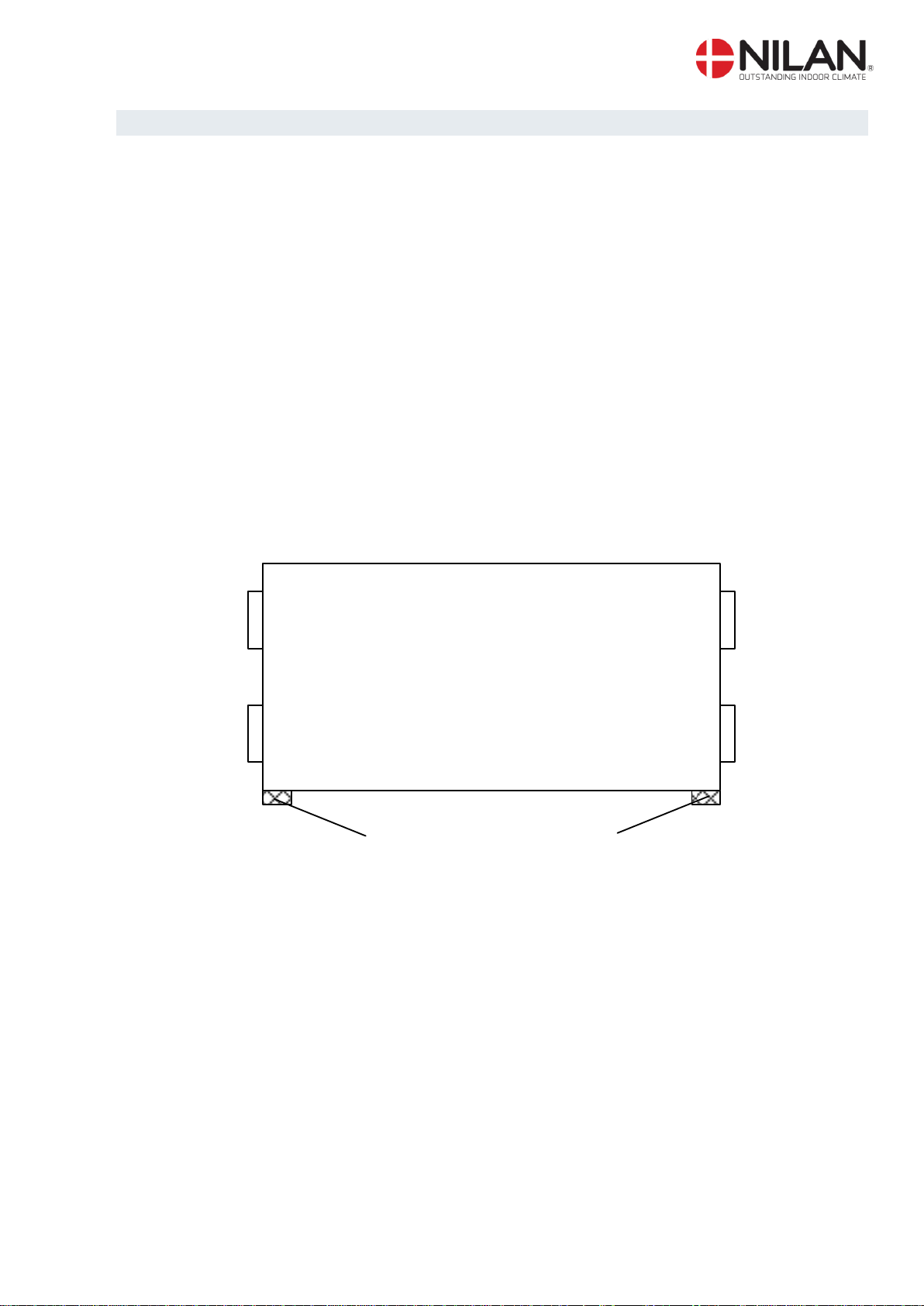
Assembly of Comfort ...................................................................................................................... 5
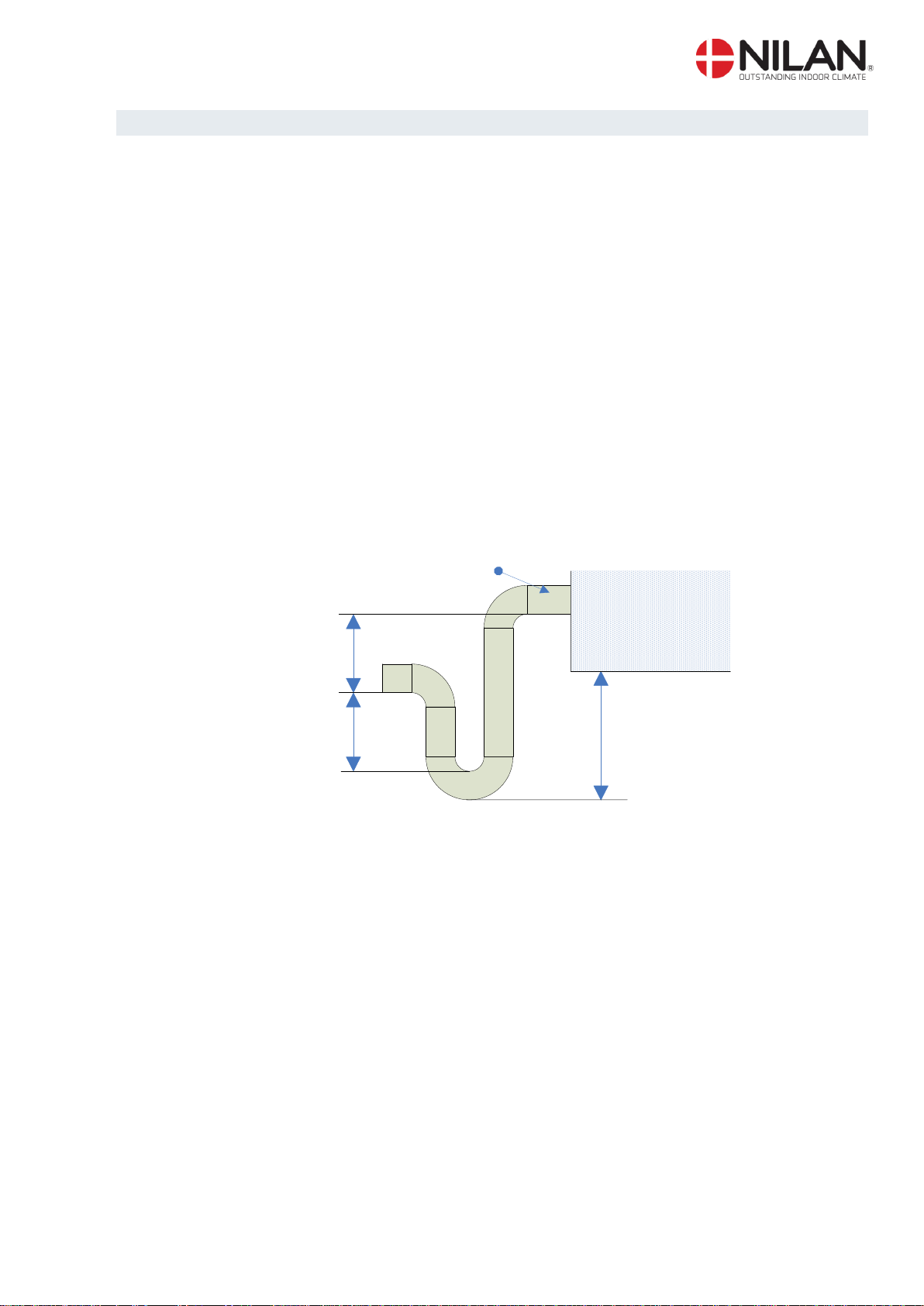
Condensation drain / water seal ..................................................................................................... 6
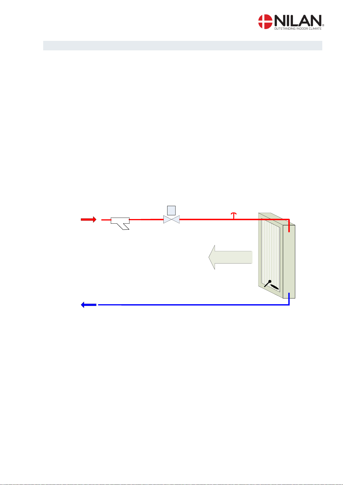
Heating surface, water.................................................................................................................... 7
Heating surface, electrical (retrofitting) ........................................................................................... 9
Activating the service menu ...................................................................................................... 10
Heating surface......................................................................................................................... 11
Air quality.................................................................................................................................. 12
Air exchange............................................................................................................................. 13
Defrost...................................................................................................................................... 14
Temp. control............................................................................................................................ 15
Inlet control............................................................................................................................... 16
Room control ............................................................................................................................ 17
Re-start..................................................................................................................................... 18
Preset....................................................................................................................................... 19
Manual...................................................................................................................................... 20
Modbus..................................................................................................................................... 21
Datalog ..................................................................................................................................... 22
System dimensions ...................................................................................................................... 23
Accessories/spare parts ............................................................................................................... 25

Nilan reserves the right to alter these instructions without prior notice Page 3 af 25
Introduction
Please control that the following documents have been delivered together with the unit:
- Directions for assembly & use (this document)
- CTS 600 directions
- Electrical chart
Comfort is designed for heat recovery with air volumes up til1200m3 / h. The energy from the ex-
haust is recovered to the inlet via the counter flow heat exchanger, where the two air streams pass
each other without coming into direct contact.
The system is prepared for retrofitting of a post-heating element (electricity or water) for supply
heating of the inlet air. The post-heating element is controlled via CTS 602.
The system comes standard with filter class F5 on the extract air and F7 on the supply air.
Operating the unit is done with the CTS 602 control. The control has many functions such as menu
based attendance, week programme, time controlled filter guard and adjustment of the velocity of
the ventilator. (Directions for the CTS 602 control is described in another document delivered with
the unit.)
Comfort is delivered tested and ready for use. Installation and start-up must be carried out by an
authorized electrician.

Nilan reserves the right to alter these instructions without prior notice Page 4 af 25
Power supply
Power supply including safety switch must be installed by an authorized electrician.
The Comfort-unit must be connected according to the attached electrical chart.
The unit is delivered with 1m test cable for the CTS 602 panel. The panel should be connected to
the CTS 602 control in the unit with cable type 2x2x0.25mm2twisted in pairs. (Maximum length
50m).
The CTS 602 panel must be placed dry and frost-proof. The panels’ integrated feeler prevents fur-
ther cooling of the building if the primary heat-supply stops by stopping the ventilation if the panel
feeler gets below a specific value. (Factory setting is 10°C; the value can be set from 1-20°C.)
CTS 602 control
If a water heating element is installed in the system, the regulation vent must be connected electri-
cally as described in the enclosed wiring diagrams.

Nilan reserves the right to alter these instructions without prior notice Page 5 af 25
Assembly of Comfort
When mounting the Comfort-unit future service and maintenance should be considered.
There is required a minimum of open space in front and behind of the unit of 60cm.
In order to ease the mounting each of the connection pieces is labeled. Please notice the labels.
The connection between the unit and the ducting should be a flexible transition.
The system must be level because of the condense outlet. The condense outlet requires a mini-
mum clearance height of 125mm beneath the outlet connection.
The exchanger is low-noise and low-vibration. However, potential vibrations spreading from the
system to the individual building parts must be taken into account. To detach the system from the
floor, we recommend that the system is placed on vibration absorbers. The vibration absorbers
must be placed diagonally on each corner to ensure that the system does not “fall down” from
them. If a water heating element is installed in Comfort 300/450/600, a clearance distance of 60cm
is required behind the system.
It is not necessary to re-insulate the system as it is delivered with a 20mm standard insulation.
Comfort
1200/5000
4 x vibration absorbers
Mounting the Comfort unit

Nilan reserves the right to alter these instructions without prior notice Page 6 af 25
Condensation drain / water seal
The Comfort unit is delivered with a 20mm condensation drain. (PVC, GF-fittings). The drain is
placed under the discharge.
The condensation drain should be carried with an even inclination of at least 1cm per
metre, frost-proof to the nearest outlet. The overflow from the safety valve should also be
carried to the nearest outlet.
To avoid frost problems it can be necessary to supply the condensation drain with a
heating cable. It is the plumbers’ responsibility to secure the drain. (See Accessories)
When the system is running, there can be a vacuum of up to 500Pa (corresponding to 50mm water
column) in the outlet. For this reason, the difference in height in the water seal must be minimum
50mm.
The water seal can dry out and avoid the water from running out of the unit. Therefore the water
seal should be tested regularly and refilled with water if necessary. An elevated height of the water
seal will reduce the need for refilling with water.
min. 112,5mm
min. 50mm.
min. 50mm.
Ø20mm drain
Comfort
Condensation drain / water seal
The water seal should be tested as described below. (the unit must be connected to the
ducting and the front door should be closed):

Nilan reserves the right to alter these instructions without prior notice Page 7 af 25
Heating surface, water
Connecting the heating surface must be done by an authorized plumber.
If the unit is placed outside or in a cold location the installation must frost secured.
The heating surface should be connected, scavenged and checked for any leakages before start-
ing the unit.
The dirt-catcher should be checked and cleaned after a thoroughly flushing of the system.
To obtain a stable control of the heating surface, the distance between the mixing loop
and heating coil must not exceed 2 meters.
Avoid routing pipes in the system in such a way that the fan cannot be removed.
Air flow
Flow
Return B3
T9
2
1
MHeating surface
3
Note that the temperature sensor T9 and frost-protection B3 is placed at the heated side of the heating
surface close to the return connection. See electrical chart.
1:
Actuator and regulating valve:
Danfoss AME 140/24V, - 3-vejsventil VZ3 DN15 Kv0,63, (Nilan delivery)
2:
Circulation pump, eg. Grundfos UPS 25-40 or equivalent (not Nilan supply)
3:
Dirt-catcher (not Nilan delivery)
4:
Shutoff valve (not Nilan delivery)
5:
Exhaust (not Nilan delivery)
Connecting the heating surface, suggestion

Nilan reserves the right to alter these instructions without prior notice Page 8 af 25
IMPORTANT regarding Danfoss Actuator type AME 140:
Re-installing the actuator must be done as described below:
1. Disconnect the power supply and remove the cover of the actuator.
2. Liberate the gear by pressing down the button as the spindle is turned up (counter clock-
wise)
3. Re-install the actuator and turn on power.
4. DIP-switch nr. 1 should be moved to ON and then to OFF.
5. The actuator is automatically calibrating for up to 6 minutes.
(The LED is flashing when calibrating and is lit constantly when finished).
6. Re-install the cover of the actuator.
The actuator should be placed in an environment of 0°C to 55°C.
Indicative performance data for the Comfort 1200 water heating element
Pipe connection: Ø15 (by factory-mounted water heating element)
Flow/return
temperatur
Airflow
Per-
forman
ce
Air supply tempera-
ture (at temperature
of 5 °C immediately
prior to the heating
element)
Pressure
drop on
water side
Pressure
drop on
air side
Water
Quantity
Recom-
mended
Kv value
for valve
[°C]
[m3/h]
[kW]
[°C]
[kPa]
[Pa]
[l/h]
40/30
400
3
26,1
5
4,3
259
0,63
600
4
23,7
8,4
8,4
344
800
4,8
22
11,8
13,5
416
1.000
5,6
20,7
15,3
19,5
480
1.200
6,2
19,6
18,7
26
537
60/40
400
4,5
36,8
2,9
4,3
196
600
6
33,1
4,8
8,4
260
800
7,2
30,5
6,7
13,5
314
1.000
8,3
28,4
8,6
19,5
361
1.200
9,3
26,8
10,5
26
403
70/40
400
5
39,9
1,6
4,3
144
600
6,5
35,6
2,7
8,4
189
800
7,9
32,7
3,7
13,5
228
1.000
9
30,4
4,7
19,5
261
1.200
10
28,6
5,8
26
291

Nilan reserves the right to alter these instructions without prior notice Page 9 af 25
Heating surface, electrical (retrofitting)
Electrical heating surface should be installed in the ducting Ø315mm, 400V, 3~.
Power supply must be installed by an authorized electrician.
Electric heating surfacel mounted in supply air duct for Comfort 1200.
There must be af safety distance of minimum 150 mm from the electrical heating element to flam-
mable material. The heating element must be insulated with a fire-resistant insulating material,
however the connection box must not be insulated. (Important: The instructions from the manufac-
turer of the heating element MUST be followed).
• Electrical assembly must be performed by a qualified electrician.
• Power supply is installed with the ventilation system.
• T7, air supply sensors, installed in supply air duct approx. 1 meter after the electrical
heating el ement.
• 0-10V signal is connected to electrical heating element.
• Signal to overheating from the electrical heating element is connected to the CTS
602 print in the ventilation system.
The Nilan supplied heating element is installed in accordance with the enclosed chart
The heating element is now an option in the software via the control panel. See the instructions on
the following pages.
See electrical chart for the ventilation unit.

Nilan reserves the right to alter these instructions without prior notice Page 10 af 25
Activating the service menu
Press and ENTER at the same time for 10 seconds. The service menu is now available. Press
multiple times until the panel shows SERVICE. Press ENTER to enter the service menu. It is
now possible to move around in the menu by using . The headlines of the service menu are
shown below:
DEFROST
ENTER
SERVICE HOTWATER
AIR
EXCHANGE
TEMP.
CONTROL
INLET
CONTROL
ROOM
CONTROL
RESTART
OFF
PRESET
OFF
MANUAL
OFF
MODBUS
ADR 30
AIR
QUALITY
DATALOG
INTV 10
Headlines in the service menu

Nilan reserves the right to alter these instructions without prior notice Page 11 af 25
Heating surface
The unit can be equipped with a heating surface.
It is possible to retrofit a heating surface. The surface must be activated in the CTS 602 control in
order to function together with the unit and for the frost-protection to be active.
When installing a heating surface T7 is the temperature sensor in the inlet.
Use of the CTS 602 panel:
- press ESC to go one step back in the menu
- press to move up or down in a menu or to adjust an
activated menu
- press ENTER to activate a menu
- press ENTER to confirm a menu
- press OFF to turn off the unit
- press ON to turn the unit on
hotwater will be
HOTWATER ENTER EL SUP
ON EL SUP
”ON”
LEGIONEL
”MON”
ENTER
ENTER
ENTER
ENTER
ENTER
EL SUP
”OFF”
LEGIONEL
OFF
LEGIONEL
”OFF”
A weekday can
be chosen,
where the
warmed up to
65°C between
01.00 and 06.00
o’clock.
Fuction is not
active.
SERVICE ENTER
DEFROST
INLET
CONTROL
TEMP.
CONTROL
PRESET
OFF
RESTART
OFF
ROOM
CONTROL
AIR
EXCHANGE
MANUAL
OFF
MODBUS
ADR 30
AIR
QUALITY
DATALOG
INTV 10
The “Central heating” menu

Nilan reserves the right to alter these instructions without prior notice Page 12 af 25
Air quality
In the ”Air quality” menu it is possible to choose between 3 types of regulation: Humidity, Humidity
+ CO2or OFF.
Use of the CTS600 panel:
- press ESC to go one step back in the menu
- press to move up or down in a menu or to adjust an
activated menu
- press ENTER to activate a menu
- press ENTER to confirm a menu
- press OFF to turn off the unit
- press ON to turn the unit on
HOTWATER
DEFROST
FUNCTION
OFF ENTERENTER FUNCTION
”OFF”
AIR
EXCHANGE
INLET
CONTROL
SERVICE ENTER
TEMP.
CONTROL
RESTART
OFF
MANUAL
OFF
PRESET
OFF
ROOM
CONTROL
AIR
QUALITY
Can be set to:
OFF, HUMIDITY or
HUM+CO2, when is
mounted.
MODBUS
ADR 30
DATALOG
INTV 10
The “Air quality” menu

Nilan reserves the right to alter these instructions without prior notice Page 13 af 25
Air exchange
In the ”Air exchange” menu it is possible to adjust 4 steps of ventilation speed (air volume). Inlet
and exhaust is to be adjusted individually at each level.
The inlet speed can be adjusted to a minimum and the exhaust can be adjusted to both a maxi-
mum and a minimum.
It is possible to delay the starting of the fan in order to give time to the register to open.
Use of the CTS600 panel:
- press ESC to go one step back in the menu
- press to move up or down in a menu or to adjust an
activated menu
- press ENTER to activate a menu
- press ENTER to confirm a menu
- press OFF to turn off the unit
- press ON to turn the unit on
Möglichkeit zur Einstellung jeder
Der Wert gibt die kleinste
zulässige Lüfterstufe des
Zuluftgebläses an (0-2).
Der Wert gibt die kleinste
zulässige Lüfterstufe des
Abluftgebläses an (1-2).
LUFT
WECHSEL ZULUFT
MIN 0
ABLUFT
MIN 1
ABLUFT
MAX 4
ENTER
SERVICE ENTER
ABTAUEN
ZULUFT
STEUERNG
TEMP.
STEUERNG
RAUM
STEUERNG
HEIZUNG
W-HEIZRG
Der Wert gibt die höchste
zulässige Lüfterstufe des
Abluftgebläses an (3-4).
ZULUFT
>1< 20%
ZULUFT
>2< 45%
ZULUFT
>3< 65%
ABLUFT
>1< 25%
ABLUFT
>3< 70%
ABLUFT
>4< 100%
ZULUFT
>4< 100%
ABLUFT
>2< 45%
Lüfterstufe ausgedrückt in % der
maximale Lüfterleistung.
LUFT
QUALITÄT
VERSöG
2 MIN
PRESET
AUS
RESTART
AUS
MANUELL
AUS
MODBUS
ADR 30
DATALOG
INTV 10
BYPASS
150 SEK
The "Air exchange" menu

Nilan reserves the right to alter these instructions without prior notice Page 14 af 25
Defrost
In the ”Defrost” menu it is possible to chose how the unit should perform during defrosting of the
evaporator in the exhaust.
” ” indicates that the menu point flashes and can be set to another value
Use of the CTS600 panel:
- press ESC to go one step back in the menu
- press to move up or down in a menu or to adjust an
activated menu
- press ENTER to activate a menu
- press ENTER to confirm a menu
- press OFF to turn off the unit
- press ON to turn the unit on
ENTER
.
AIR
USER
ENTER BYPASS
”OPEN”
ENTER
BYPASS
”CLOSE”
BYPASS
OPEN
EXCH.
PERIODE
90 MIN
TERMINAT
T4/6 °C4
AIR
”USER”
EXCH.
”OFF”
AIR
”LOW”EXCH.
AIR EXCH.
Fixed off-period in
minutes between two
defrost modes. Can
be set to anything
from 15 to 720
minutes.
Adjustable temperature
for discontinuing
defrosting measured on
T4, discharge censor
Low-level
injection during
defrosting
Custom injection
during defrosting.
Discontinued
injection during
defrosting
DEFROST
HOTWATER
AIR
EXCHANGE
INLET
CONTROL
SERVICE ENTER
TEMP.
CONTROL
RESTART
OFF
MANUAL
OFF
PRESET
OFF
ROOM
CONTROL
MODBUS
ADR 30
AIR
QUALITY
DATALOG
INTV 10
The "Defrost" menu

Nilan reserves the right to alter these instructions without prior notice Page 15 af 25
Temp. control
In the ”Temp. control” menu it is possible to chose a room temperature where the unit stops in
order to avoid further cooling of the building if the primary heating shuts down.
Use of the CTS600 panel:
- press ESC to go one step back in the menu
- press to move up or down in a menu or to adjust an
activated menu
- press ENTER to activate a menu
- press ENTER to confirm a menu
- press OFF to turn off the unit
- press ON to turn the unit on
HEATING
SURFACE
TEMP.
CONTROL
AIR
EXCHANGE
DEFROST
INLET
CONTROL
SERVICE ENTER
ROOM
CONTROL
The unit stops at this
room temperature (1-
20°C) - - means that the
function is unactive.
- - should be chosen if
the panel is placed in a
cold environment.
SENSOR
”EXTERNAL”
SENSOR
PANEL SENSOR
”PANEL”
PRIORITY
”HP + EXT”
PRIORITY
”HF”
ENTER ENTER
ENTER
SENSOR
”EXHAUST”
ROOM
LOW 10°C
PRIORITY
HP + EXT
EXTERNAL
-1 °C PRIORITY
”OFF”
Indicates which sensor
that needs to be the
controlling one.
PANEL T15 (Panel
sensor).
ROOM EXT: T10 (to be
installed in representative
extraction fitting).
EXHAUST: T3 (Exhaust)
AIR
QUALITY
Option for an extra heating
element via relay output,
R8. R8 is an accessory and
the option is only possible
via accessory pcb.
The temperature is added
or subtracted to/from the
set point shown in the main
menu.
OFF: ventilation
without heating surface
HP:ventilation only
with heatrecovery
HP+EXT:ventilation with
heatpump and heating
surface activ
RESTART
OFF
MANUAL
OFF
PRESET
OFF
MODBUS
ADR 30
DATALOG
INTV 10
The "Temp. control" menu

Nilan reserves the right to alter these instructions without prior notice Page 16 af 25
Inlet control
In the ”Inlet control” menu it is possible to adjust the regulation of the inlet. The menu is only ac-
cessible when the unit has a heating surface installed.
The ”Inlet control” menu should only be adjusted by persons with knowledge of control
engineering.
” ” indicates that the menu point flashes and can be set to another value.
Use of the CTS600 panel:
- press ESC to go one step back in the menu
- press to move up or down in a menu or to adjust an
activated menu
- press ENTER to activate a menu
- press ENTER to confirm a menu
- press OFF to turn off the unit
- press ON to turn the unit on
HEATING
SURFACE
TEMP.
CONTROL
AIR
EXCHANGE
DEFROST
SERVICE ENTER
ROOM
CONTROL
INLET
CONTROL ENTER GAIN 7.0%/°
INTEGRAL
120 s
N-ZONE
0.5°C
TMP-RAMP
0.10°/s
CAP-RAMP
0.5%/s
AIR
QUALITY
RESTART
OFF
MANUAL
OFF
PRESET
OFF
MODBUS
ADR 30
DATALOG
INTV 10
The "Inlet control" menu

Nilan reserves the right to alter these instructions without prior notice Page 17 af 25
Room control
In the ”Room control” menu it is possible to adjust the regulator for controlling the room tempera-
ture.
The ”Room control” menu should only be adjusted by persons with knowledge of control
engineering.
” ” indicates that the menu point flashes and can be set to another value.
Use of the CTS600 panel:
- press ESC to go one step back in the menu
- press to move up or down in a menu or to adjust an
activated menu
- press ENTER to activate a menu
- press ENTER to confirm a menu
- press OFF to turn off the unit
- press ON to turn the unit on
HEATING
SURFACE
ROOM
CONTROL
TEMP.
CONTROL
AIR
EXCHANGE
DEFROST
INLET
CONTROL
SERVICE ENTER
ENTER RESPONSE
NORMAL
RESPONSE
”USER”
RESPONSE
”FAST”
RESPONSE
”NORMAL”
GAIN 6.0°/°
INTERGRAL
6m
RESPONSE
”SLOW”
ENTER
N-ZONE
2.0°C
ENTER RESPONSE
USER
N-ZONE
2.0°C
The RESPONSE
menu is only
accessible when the
CTS 600 control is
set up to heating
surface
Rum control parametres:
Response Gain Integral
Slow 4.0 12
Normal 6.0 6
Fast 8.0 4
User 6.0 6
AIR
QUALITY
RESTART
OFF
MANUAL
OFF
PRESET
OFF
MODBUS
ADR 30
DATALOG
INTV 10
The "Room control" menu

Nilan reserves the right to alter these instructions without prior notice Page 18 af 25
Re-start
Fire alarms can be acknowledged automatically in connection with fire drills/testing. A condition for
acknowledgement is that the fire thermostat input has returned to normal state.
HEATING
SURFACE
TEMP.
CONTROL
AIR
EXCHANGE
DEFROST
INLET
CONTROL
SERVICE ENTER
AIR
QUALITY
MANUAL
OFF
PRESET
OFF
MODBUS
ADR 30
DATALOG
INTV 10
ENTER RESTART
”OFF”
ROOM
CONTROL
RESTART
OFF
”FIRE”
FIRE: Auto restart
when fire input is back
to normal
RESTART
The "Restart"

Nilan reserves the right to alter these instructions without prior notice Page 19 af 25
Preset
” ” indicates that the menu point flashes and can be set to another value.
RESTORE menu allows you to reload a copy of the installation setup.
By keeping the ESC + key pressed for 5 seconds a new menu item RESTORE appear, this is
then acceptable / activated by pressing the ENTER
Use of the CTS600 panel:
- press ESC to go one step back in the menu
- press to move up or down in a menu or to adjust an
activated menu
- press ENTER to activate a menu
- press ENTER to confirm a menu
- press OFF to turn off the unit
- press ON to turn the unit on
HEATING
SURFACE
AIR
EXCHANGE
DEFROST
INLET
CONTROL
SERVICE ENTER
TEMP.
CONTROL
MANUAL
OFF
ROOM
CONTROL
PRESET
OFF ENTER PRESET
”OFF”
PRESET
”STANDARD” Factory settings are
chosen when pressing
ENTER at
”STANDARD”. If a
heating element is
installed, it must be
activated in the service
menu again.
AIR
EXCHANGE
”BACKUP”
”RESTORE”
PRESET
PRESET The backup will be
saved.
The backup is restored.
Subsequently, the
system must be
restarted.
MODBUS
ADD 30
DATALOG
INTV 10
RESTART
OFF
The "Preset" menu

Nilan reserves the right to alter these instructions without prior notice Page 20 af 25
Manual
In the ”Manual” menu it is possible to test the functions of the unit manually.
” ” indicates that the menu point flashes and can be set to another value.
Use of the CTS600 panel:
- press ESC to go one step back in the menu
- press to move up or down in a menu or to adjust an
activated menu
- press ENTER to activate a menu
- press ENTER to confirm a menu
- press OFF to turn off the unit
- press ON to turn the unit on
Test der
Abtaufunktion.
Manueller Test
deaktiviert
(normaler
Betriebsmodus).
HEIZUNG
W-HEIZRG
LUFT
WECHSEL
ABTAUEN
ZULUFT
STEUERNG
SERVICE ENTER
TEMP.
STEUERNG
PRESET
AUS
RAUM
STEUERNG
MANUELL
AUS MANUELL
”AUS”
MANUELL
”ABTAUEN”
MANUELL
”ZULUFT”
MANUELL
”ABLUFT”
MANUELL
”VENT+HEI”
ENTER
Test der Zuluft
Test der Abluft
Test der Lüftung
und des
Heizbetriebs.
Während des
Tests wird 50%
Heizsignal
gegeben.
LUFT
QUALITÄT
MANUELL
”KLAPPE”
Test der Klappe
MODBUS
ADD 30
DATALOG
INTV 10
RESTART
AUS
The "Manual" menu
This manual suits for next models
2
Table of contents
Other nilan Heating System manuals
Popular Heating System manuals by other brands

VWR
VWR VisiScope 300 Series instruction manual

Fenix
Fenix MADPSP 30 installation manual

Magnum
Magnum Sol 300 installation manual

JOSAM
JOSAM JO960 A Operator instruction and safety regulations

Omega
Omega HRV-200 Owners manual and installation manual

Venmar
Venmar 6LC Installation, operation and service instructions

Juwent
Juwent TROPIC-1 Original instruction manual

Aereco
Aereco DXA 230 REFERENCE Installation and maintenance instruction

Toyostove
Toyostove Laser 30 Type B user guide

Oxygen
Oxygen TYPHON 2000 manual

BPC
BPC VORTICE VORT HR 250 NETI Instruction booklet

Mitsubishi Electric
Mitsubishi Electric VL-250CZPVU Series installation manual