nilan CTS 150 User manual

USER MANUAL
CTS150 BY NILAN
Comfort 200 Top (English)
Version 2.00 - 05.07.2017

TABLE OF CONTENTS
Safety
Power supply................................................................................................................................................................................................................................................................... 3
Disposal............................................................................................................................................................................................................................................................................................. 3
Ventilation system....................................................................................................................................................................................................................................................3
Quick guide
Control panel............................................................................................................................................................................................................................................................................... 4
Functions..............................................................................................................................................................................................................................................................................4
Alarms ....................................................................................................................................................................................................................................................................................4
Fan speed.............................................................................................................................................................................................................................................................................5
Humidity control..........................................................................................................................................................................................................................................................5
General information
Unit type........................................................................................................................................................................................................................................................................................... 6
Product description..................................................................................................................................................................................................................................................6
Operation and maintenance
Maintenance ................................................................................................................................................................................................................................................................... 7
Water trap...........................................................................................................................................................................................................................................................................7
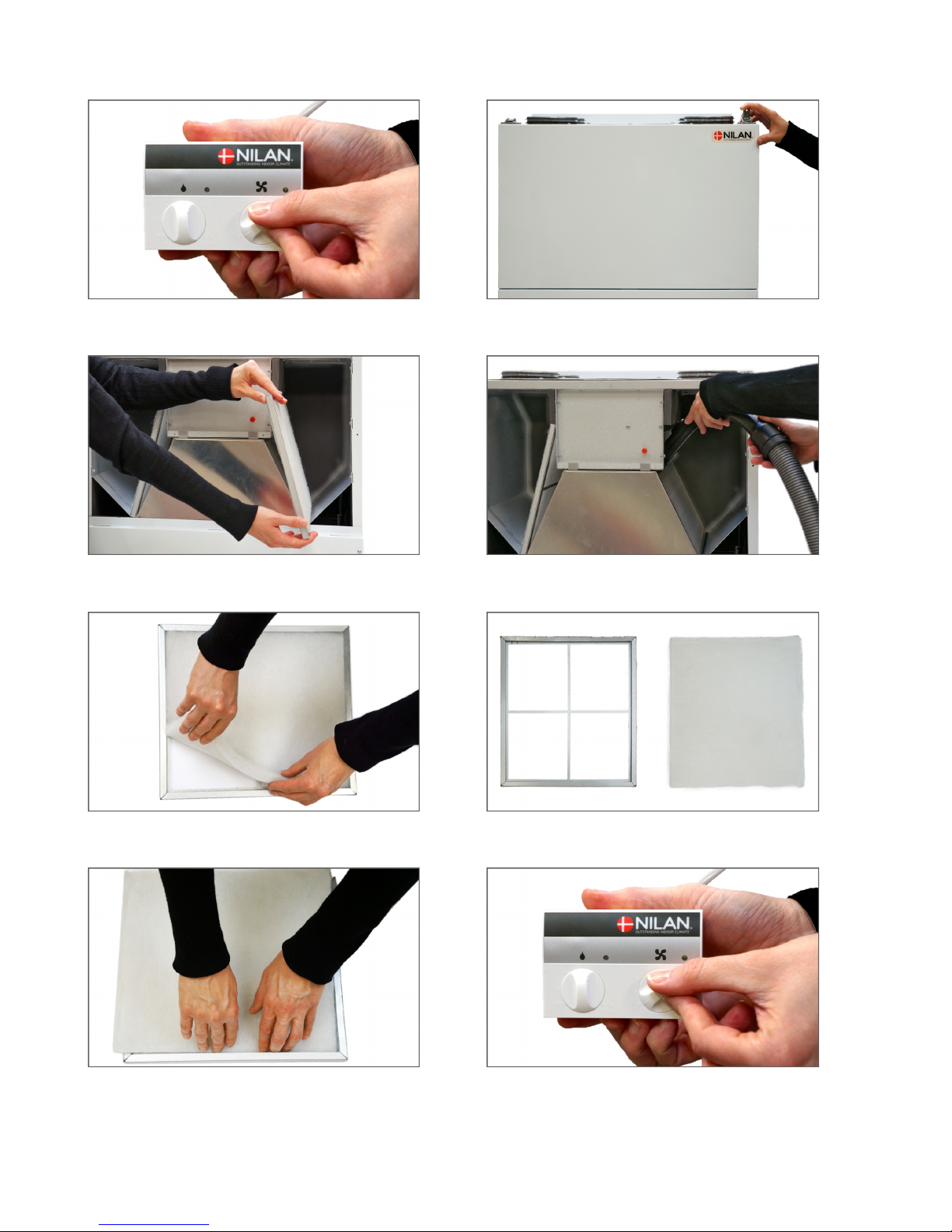
Filter replacement.....................................................................................................................................................................................................................................................7
Illustration of filter change.............................................................................................................................................................................................................................. 8
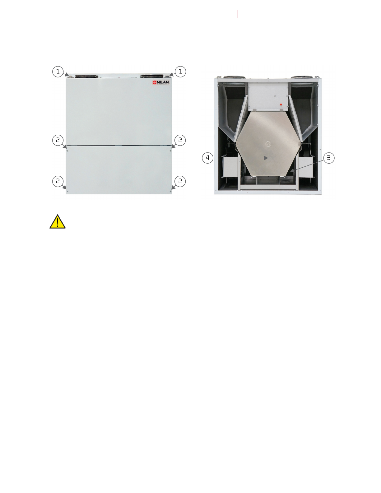
Heat exchanger.............................................................................................................................................................................................................................................................9
Product data
Declaration of compliance............................................................................................................................................................................................................................ 10
Ecodesign data Comfort 200 Top..........................................................................................................................................................................................................11
2

Safety
Power supply
CAUTION
Always disconnect mains electricity to the unit if a fault occurs which cannot be rectified via the
control panel.
CAUTION
If a fault occurs on the electricity-conducting elements of the unit, always contact an
authorised electrical installer to rectify the fault.
CAUTION
Always disconnect mains electricity to the unit before opening the doors, e.g. for installation,
inspection, cleaning and filter change.
Disposal
Ventilation system
Nilan units mainly consist of recyclable materials. They should therefore not be
disposed of with household refuse. Take them to your local recycling centre.
Comfort 200 Top (English) BY NILAN
3

Quick guide
Control panel
Functions
1
2
4
3
The CTS150 control panel provides the following functions:
1. Setting fan speeds: 0 (off) - 1 - 2 - 3 - 4
2. Green diode: On when the unit is running
3. Setting low humidity: Can be set between 15 and 45%
4. Red diode: Flashes in the event of an alarm
Alarms
If the unit is in alarm mode, the RED diode on the CTS150 control panel will flash.
Alarm description
ID Alarm Critical Signal
1. T3 temperature sensor missing No
2. T4 temperature sensor missing No
3. T8 temperature sensor missing No
4. temperature sensor missing No
5. De-icing alarm No
6. Filter alarm No
• If the unit records more than 5 de-icing registrations within 24 hours, the de-icing alarm (ID = 5) is
triggered
• To re-activate the de-icing alarm, disconnect electricity and restart the unit
• The unit shuts down when a critical alarm is active
Reset alarm:
1. Turn the fan speed selector as follows: → 0 → 4 → 0
2. Turn the selector to the fan speed required
4

Fan speed
Recommended fan speed setting in relation what the installer set.
0 The system may only be switched off, for example, in an emergency where residents are asked
to go inside, close doors and windows and shut down the ventilation system.
NB! When the system is shut off for longer periods, condensation can form in the ductwork,
which can cause mould.
1 Use this setting if you are away from home for some time, e.g. on holiday.
NB! When the system is set to low humidity, it can be set at fan speed 1.
2 The system is set at fan speed 2 during normal operation. The air volume at fan speed 2
corresponds to the basic air volume set for the home.
NB! Automatic humidity control changes the system's function, i.e. it runs at high or low fan
speed as necessary.
3 Use this fan speed when you have visitors in your home or if you have lit candles.
NB! Don't forget to return to level 2 when your visitors have left!
4 Use this fan speed if holding a party with lots of guests for example.
NB! This level can also be used to run a cooker hood (if your cooker hood is connected to the
ventilation system).
Humidity control
Humidity control overrides the setting on the control panel.
We recommend that you set the system to run at low ventilation when humidity in your home gets
below 30%. You can set low ventilation at low humidity in the range of 15 to 45%. We recommend a
setting of 30%.
The integrated humidity control system will control the ventilation level automatically on demand. The
system measures air humidity all the time, and calculates an average level for the last 24-hour period.
This level is the basis for ventilation control.
In the event of longer periods with freezing outdoor temperatures, air humidity in the home may fall to
an low level. When air humidity indoors is too low, the ventilation level is reduced until the air humidity
returns to normal.
At high humidity, e.g. after baths and showers, ventilation will be stepped up until the humidity level in
the home returns to normal.
Comfort 200 Top (English) BY NILAN
5

General information
Unit type
Product description
Comfort 200 Top is a ventilation unit with heat recovery. The unit is designed for air flows up to 308
m3/h at 100 Pa external duct pressure.
The unit draws the humid, vitiated air out of the dwelling via the bathroom, WC, kitchen and utility room
and introduces fresh outdoor air into habitable rooms such as living room, bedrooms and office. The
cold outdoor air is heated up in the heat exchanger by the warm exhaust air.
Comfort 200 Top is supplied as standard with a G4 filter in the outdoor air and extract air ducts. If it is
wished to filter the outdoor air for pollen, an F7 filter can be purchased as an accessory and mounted
subsequent.
1. Duct connections
2. Electrical connections
3. Automatic control system
4. Bypass-damper
5. Extract air filter G4 (left model)
6. Outdoor air filter G4 (F7 filter is fitted here) (left model)
7. Supply air fan (inlet air)
8. Extract air fan (outlet air)
9. Counterflow heat exchanger
10. Condensate drain
6

Operation and maintenance
Maintenance
Nilan’s ventilation units last for many years, but to get the best out of them whilst avoiding
unnecessary electricity consumption, correct maintenance is important.
The following parts require regular maintenance:
• Water trap
• Filters
Water trap
The water trap may dry out and thus prevent water escaping from the condensate tray, as air will blow
into the unit. Condensate will accumulate in the condensate tray and at some point the water will
overflow, possibly causing damage to the surface below the unit.
The water trap should therefore be checked regularly and filled with water, especially in the summer,
where the risk of drying out is highest.
Filter replacement
The filters are intended to protect the fans and heat exchanger from being covered with dust and dirt.
Always change the filters before they become blocked to ensure maximum efficiency. The Nilan G4
filters should be replaced every 3 months for normal use. We recommend changing them for the first
time after 30 days for new buildings, as they can quickly become blocked by building dust.
If the filters are not changed regularly, ventilation is reduced at the expense of the indoor climate and
the unit will use more electricity than necessary, and can be damaged.
Comfort 200 Top (English) BY NILAN
7

Illustration of filter change
1. The unit must be turned off at the control panel before
opening the door
2. The suitcase fittings are loosened and the upper door is
removed
3. Remove the two filters from the unit 4. It is a good idea to vacuum the filter chamber to
remove any dirt which has collected there
5. Remove the filter pad from the filter frame 6. Place the new filter pad with its smooth side down in
the filter frame
7. Carefully fix the filter pad in place in the filter frame,
pushing it well out into the sides. Replace the filter in the
unit with the filter pad facing upwards
8. Reset the alarm:
1. Turn the fan speed knob as follows: → 0 → 4 → 0
2. Turn the knob to the desired fan speed
8

Heat exchanger
The heat exchanger should be serviced every two years or so to remove dirt and dust, thereby
ensuring unimpeded air flow. A blocked heat exchanger will cause the power consumption to go up.
ATTENTION
Turn off the unit at the mains socket before opening the front doors
• The suitcase fittings (1) are loosened and the upper door is removed
• Release the 4 screws in the lower front door (2) with a screwdriver and lift the door out
• Pull the sensor (3) out of the heat exchanger (Left model)
• Carefully pull the heat exchanger (4) out of the unit
• Place the heat exchanger in a shower compartment and spray it with hot water
• If necessary, wipe down the inside of the unit with a damp cloth
• Allow the heat exchanger to drain well before refitting it in the unit
• The unit must then run at its highest fan speed for about 15 min.
Comfort 200 Top (English) BY NILAN
9

Product data
Declaration of compliance
10

Ecodesign data Comfort 200 Top
SEC* average climate - 38.1 kWh/(m2.a)
SEC* cold climate - 76.8 kWh/(m2.a)
SEC* warm climate - 13.3 kWh/(m2.a)
SEC-Class A
Type Residential ventilation unit
Type of drive Variable speed drive
Type of heat recovery system Recuperative (counterflow heat exchanger)
Thermal efficiency of heat recovery 89 %
Maximum flow rate 308 m3/h (100 Pa)
Electric power input of fan drive, including any motor control equipment, at
maximum flow rate 77.6 W
Sound power level (LWA) 56 dB(A)
Reference flow rate 0.060 m3/s (215.6 m3/h)
Reference pressure difference 50 Pa
SPI 0.33 W/(m3/h)
Central demand control 0.85
Maximum internal leakage 0.17 %
Maximum external leakage 0.34 %
Visual filter warning
A yellow light flashes on the user panel when filters need changing. To
maintain the performance and energy efficiency of the unit it is very
important to change filters regularly.
Disassembly instructions www.nilan.dk
* Specific energy consumption
AEC - annual electricity consumption 343 kWh/år (100 m2)
AHS** average climate 4603 kWh (100 m2)
AHS** cold climate 9004 kWh (100 m2)
AHS** warm climate 2081 kWh (100 m2)
** Annual heating saved
Comfort 200 Top (English) BY NILAN
11

Nilan A/S
Nilanvej 2
DK-8722 Hedensted
Tlf. +45 76 75 25 00
Fax +45 76 75 25 25
www.nilan.dk
United Kingdom:
S L Services
25 St Leonards Road, Horsham
RH13 6EH West Sussex
Tlf. +44 (0) 7919 444452
www.nilanuk.com
Ireland:
Nilan Ireland
Ballylahive, Abbeydorney
Tlf. +353 (0) 87 9798361
www.nilanireland.ie
Document no.B11_Comfort_200-Top_GB
Nilan A/S disclaims all liability for any errors and omissions in printed instructions - and for loss, damage or injury arising from the published material, whether this is due to errors or
inappropriate information in the material or other causes. Nilan A/S reserves the right to make changes to products and instructions without prior warning. All trademarks are the property of
Nilan A/S, and all rights are reserved.
Table of contents
Other nilan Ventilation manuals