Venmar AVS S10 ERV 41700 User manual

ENERGY RECOVERY VENTILATOR
Venmar AVS S10 ERV
Part no. 41700
Low speed: 50 CFM (0.2 in. w.g.), selectable 65 CFM
High speed: 100 CFM (0.4 in. w.g.), selectable 85 CFM
VB0198
CONSTRUCTION
• 22 ga. galvanized steel housing and door
• One-piece molded insulation shell,
(expanded polystyrene; UL 94 HF-1 certied)
• Galvanized steel 5" diameter ports*
• Steel door hinges and latches
• Cold side ports with plastic ring; allow vapor barrier sealing
• No drain required
*All units ports were created to be connected to ducts having a
minimum of 5” diameter, but if need be, they can be connected to
bigger sized ducts by using an appropriate transition (e.g.: 5” diameter
to 6” diameter transition).
MOTORS
• Two high reliability, external rotor PSC motors, totally enclosed and
thermally protected
• Backward blowers, can support high static pressure environment
FILTERS
• Two washable 20 ppi reticulated polyester urethane foam lters,
UL 900 class 2 certied
• Optional MERV 7 lter kit, part no.: 21030 (additional 0.1 in. w.g.
static pressure to be considered) (sold separately)
ERV CORE
• Crossow aluminum-polymerized paper core, UL723 certied
• Hydroscopic polymer exchange water by direct vapor transfer using
molecular transport without the need of condensation
• Constructed of alternate layers of corrugated aluminum material
and polymeric bactericide dessiccant impregnated media; will not
promote growth of mold or bacteria
• Unique rectangular ute design to provide very low pressure drop
values
Controls
• Integrated push-button control for Low or High speed operation.
• For a complete list of optional main and auxiliary controls available,
refer to the Wall Control Compatibility Chart on last pages of wall
controls specication sheet, available at www.venmar.ca.
• For more details about controls, refer to the Main and auxiliary wall
controls user guide, also available at www.venmar.ca.
• Removable terminal block included for quicker low voltage control
connections.
• LED indicator shows operating modes and error codes.
• Unit must be permanently energized, no control should be installed
on power supply of unit.
Air Flow
• Pressure taps and balancing chart to allow easier balancing of the
unit
• Integrated balancing/backdraft dampers in cold supply and cold
exhaust ports
Defrost Cycles
• Choice of regular or extended defrost cycles, according to climatic
conditions
• To set extended defrost cycles, refer to unit installation manual
Requirements and standards
• HVI certied
• Complies with the UL 1812 requirements regulating the installation
of Energy Recovery Ventilators
• Complies with the CSA C22.2 no. 113 Standard applicable to ventilators
• Complies with CSA C444 requirements regulating the installation of
Energy Recovery Ventilators
REGULAR DEFROST CYCLES
OUTSIDE TEMPERATURE*DEFROST IN MINUTES / AIR EXCHANGE IN MINUTES
°C °F LOW SPEED HIGH SPEED
WARMER THAN -10 WARMER THAN 14 NODEFROST NODEFROST
FROM -10 TO -15 FROM 14 TO 5 6/40 9/40
FROM -15 TO -27 FROM 5 TO -17 6/20 9/20
-27 AND LESS -17 AND LESS 8/12 11/12
Warranty
The Venmar AVS S10 ERV is protected by a 5-year warranty on parts
only, with the original proof of purchase.
* Outside temperature is read by a thermistor located inside the unit,
next to fresh air from outside port.

VENMAR AVS S10 ERV
27 /8”
22”
Ø5” TYP.
20”
9”
VK0088A
• Optional chains and springs kit (sold separately,
part no. 61239 for wood or metal construction) VD0329
VO0256
2 x
2 x
Exhaust air
to outside
Fresh air
from outside
Fresh air
to building
Exhaust air
from building
120 volts, 0.8 A
3 ft. power cord
Integrated pressure taps
for balancing
Balancing dampers,
backdraft dampers
22 ga. galvanized
steel door
HORIZONTAL INSTALLATION ONLY
32 lb.
UNIQUE 3 EASY STEPS FOR CEILING INSTALLATION
TOP VIEW
BOTTOM VIEW
Removable terminal block to
ease wall control connection.
Use 4-wire, 22 AWG cable
(purchase separately).
Bend integrated hooks
(2 on the same side)
and hang the unit.
Mount brackets to ceiling.
Clip the other side of
the unit to the brackets.
OR ALTERNATE INSTALLATION
• Integrated dampening device
to prevent vibration transmission
VH0104
VH0105
Example of a fully ducted installation
Example of a central draw point installation
Allow 24" x 30" minimum for access door.

ENERGY PERFORMANCE
SUPPLY
TEMPERATURE
NET AIR FLOW
POWER
CONSUMED
WATTS
SENSIBLE
RECOVERY
EFFICIENCY
APPARENT
SENSIBLE
EFFECTIVENESS
LATENT RECOVERY/
MOISTURE
TRANSFER
°C °F L/SCFMM
3/H
HEATING
03223488244 67 75 55
0 32 30 64 109 55 65 73 51
0 32 40 85 144 70 61 69 47
-25 -13 24 50 85 36 51 79 39
COOLING TOTAL RECOVERY EFFICIENCY
35 95 24 50 85 44 54
NOTE: All specications are subject to change without notice.
Coldshield™ Protection
❄❄❄❄
✹
PREVENTION MODE
(EXTRA DEFROST ADDED
TO REGULAR DEFROST)
PROTECTION MODE
(ERV UNIT SET ON EXHAUST DEFROST)
TEMPERATURE OF SUPPLIED AIR
IN DWELLING
VM0003A
NORMAL OPERATING MODE
• ERV unit is equipped with an electronic
supplemental protection to stop air
distribution in dwelling if air distribution
temperature drops below freezing point,
due to abnormal conditions.
ERV UNIT MODES BASED ON AIR DISTRIBUTION TEMPERATURE
VF0060
VF0060
VF0059
VENTILATION PERFORMANCE
0
0.1
0.2
0.3
0.4
0.5
0.6
0.7
0.8
0.9
1. 0
0 102030405060708090100110120130
12
LOW SPEEDS:
(1,2)
HIGH SPEEDS:
VG0094A
NET AIRFLOW (CFM)
EXTERNAL STATIC PRESSURE (IN. W.G.)
34
(3,4)
NOTE: Low speed and high speed are factory set,
low speed and high speed are selectable.
Simplied Installation (connection to a forced air system)
VJ0124
B
A
Supply-return
A + B = not less than 10 ft. (3.1 m) VJ0125
B
A
NOT Return-return!
Accoustic Noise Power Chart (dBA)
Minimum 18 in.
(0.5 m)
The data shown on left chart come from measurement performed
according to ISO 5136 Standard. These data represent the sound
power directly measured at the fresh air distribution port and
exhaust air from building port. To get the actual noise level in the
room, consider noise attenuation resulting from total ductwork
installation.
Airow Fresh air
to building port
Exhaust air
from building port
100 CFM at 0.4 in. w.g. 67.8 dBA 58.3 dBA
55 CFM at 0.1 in. w.g. 58.0 dBA 49.4 dBA

www.venmar.ca S10ERVd150407
Residential Products Group, 550 Lemire Blvd., Drummondville, Qc, Canada J2C 7W9 - Tel.: 1-800-567-3855 Fax: 1-800-567-1715
Project: REMARKS
Location:
Part no.: 41700
Qty.:
Submitted by: Date:
VENMAR AVS S10 ERV ARCHITECTURAL SPECIFICATIONS
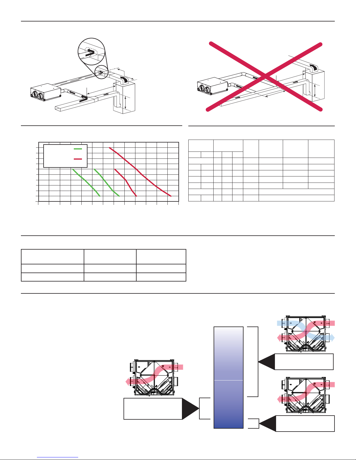
AIRFLOW
• High static pressure backward blowers shall perform a minimum of
68 CFM @ 1.0 in. w.g.
• Optional high speed: 85 CFM
• Optional low speed: 65 CFM
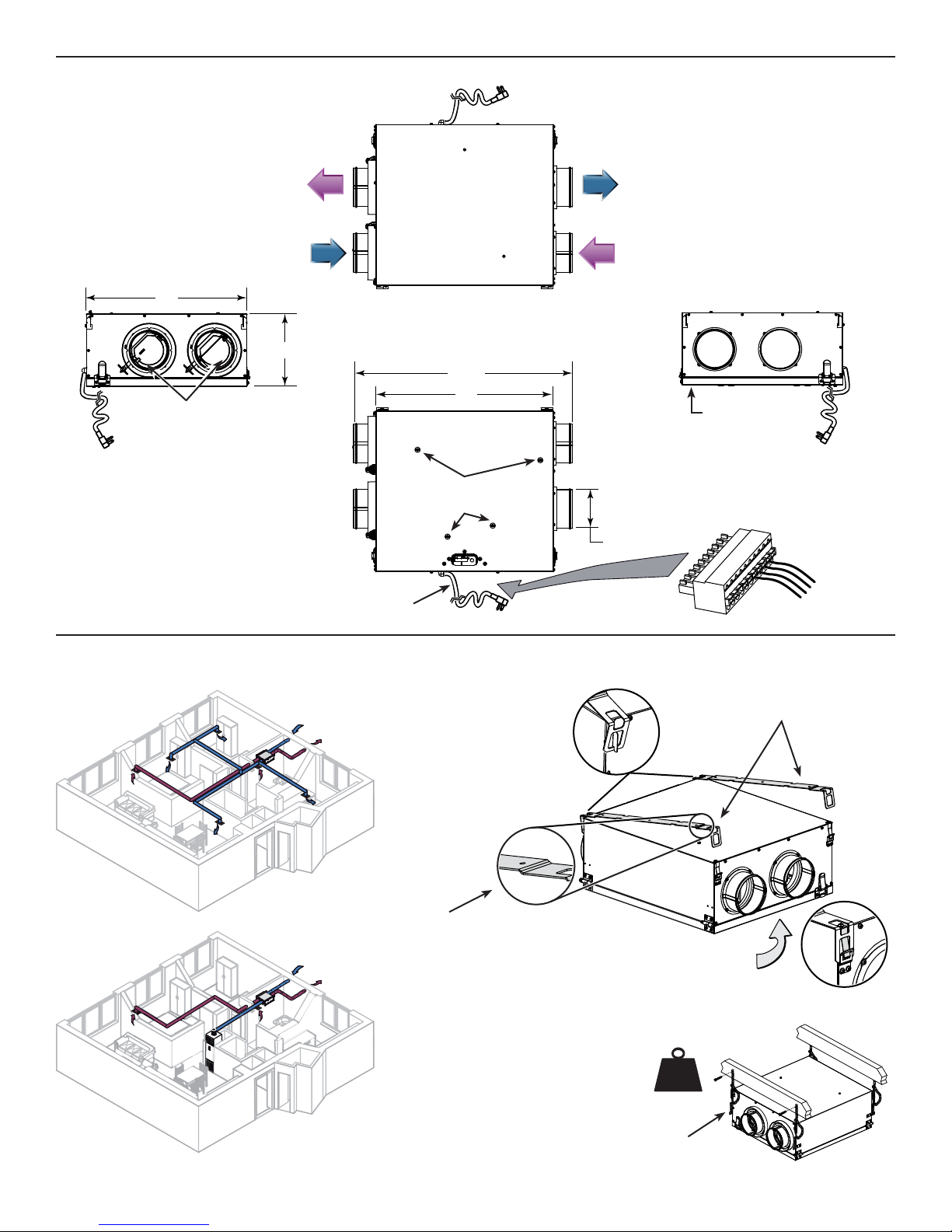
CONSTRUCTION
• Housing and door shall be made of 22 ga. galvanized steel
• Insulation shall be made of one-piece molded expanded polystyrene,
UL 94 HF-1 certied
• 5" diameter ports shall be made of galvanized steel
• Door hinges and latches shall be made of steel
• Cold side ports shall have plastic ring to allow vapor barrier sealing
• Unit construction and components shall be UL and CSA certied
• Unit shall operate all year long without drain
• Weight shall not exceed 32 lb.
• Fresh air from outside and Exhaust air to outside ports shall be located
on same side
• Backdraft dampers shall be integrated in cold supply and cold
exhaust port
• ERV unit shall be HVI certied
MOTORS
• Unit shall have two high reliability, external rotor PSC motors, totally
enclosed and thermally protected
• The backward blowers shall support high static pressure environment
• The insulation class shall be B
FILTERS
• ERV unit shall have two washable 20 ppi reticulated polyester
urethane foam lters, UL 900 class 2 certied
• Optional MERV 7 lter kit shall be available, part no.: 21030
ERV CORE
• The ERV core shall be a crossow aluminum-polymerized paper core,
UL723 certied
• Hydroscopicpolymerexchangewaterbydirectvaportransfershalluse
molecular transport without the need of condensation
• The ERV core shall be constructed of alternate layers of corrugated
aluminum material and polymeric bactericide dessiccant
impregnated media; and shall not promote growth of mold or bacteria
• The ERV core design shall be made of rectangular utes to provide
very low pressure drop values
Controls
• Unit shall be equipped with an integrated push-button control for
Low or High speed operation
• Choice of low voltage main controls (not included) shall be
energized by ERV unit
• Optional low voltage auxiliary controls (not included) shall be
energized by ERV unit
• Removable terminal block shall be included for quicker low voltage
control connections
• A LED indicator shall indicate operating modes as well as error codes
• ERV unit shall be permanently energized, no control shall be installed
on power supply of unit
Air Flow Balancing
• Unit door shall be equipped with pressure taps as well as a
balancing chart to allow verication of balancing of the ERV unit
• Balancing dampers shall be integrated in cold supply and cold
exhaust ports
Defrost Cycles
• Unit operation shall include a choice of regular or extended defrost
cycles, according to climatic conditions
• Unit shall be equipped with Coldshield™ protection to stop air supply
in dwelling if air supply temperature drops below freezing point, due
to abnormal conditions.
Accoustic Noise Power
• The unit shall have a maximum acoustic noise power of 58.0 dBA
on low speed at 0.1 in. w.g. and 67.8 dBA on high speed at 0.4 in. w.g.,
measured at fresh air to building port.
• The unit shall have a maximum acoustic noise power of 49.4 dBA
on low speed at 0.1 in. w.g. and 58.3 dBA on high speed at 0.4 in. w.g.,
measured at exhaust air from building port.
Requirements and standards
• Shall be HVI certied as per CSA C439 Standards
• Shall comply with the UL 1812 requirements regulating
the installation of Energy Recovery Ventilators
• Shall comply with the CSA C22.2 no. 113 Standard
applicable to ventilators
• Shall comply with CSA C444 requirements regulating
the installation of Energy Recovery Ventilators
Warranty
Unit shall be protected by a 5-year warranty on parts only, with the
original proof of purchase.
Other Venmar Ventilation manuals