Nilfisk-Advance PEGASUS PZC-M1 Manual

Automatic Pump Station
PEGASUS PZC-M1/PZE-M2/CIP-M3
Directions for use..................... .8 - 24
Betriebsanleitung..................... 25 - 42
Mode d’emploi ....................... 43 - 60
Instrucciones de uso .................. 61 - 78
FR
DE
ES
EN

2
Nilsk FOOD
Contents EN
1. Preface ........................................................... 3
2. Connections to Low Pressure System................ 4
2.0 Directions for Mounting................................ 4
2.1 Water Connection ........................................ 4
2.2 Compressed-Air Connection........................ 4
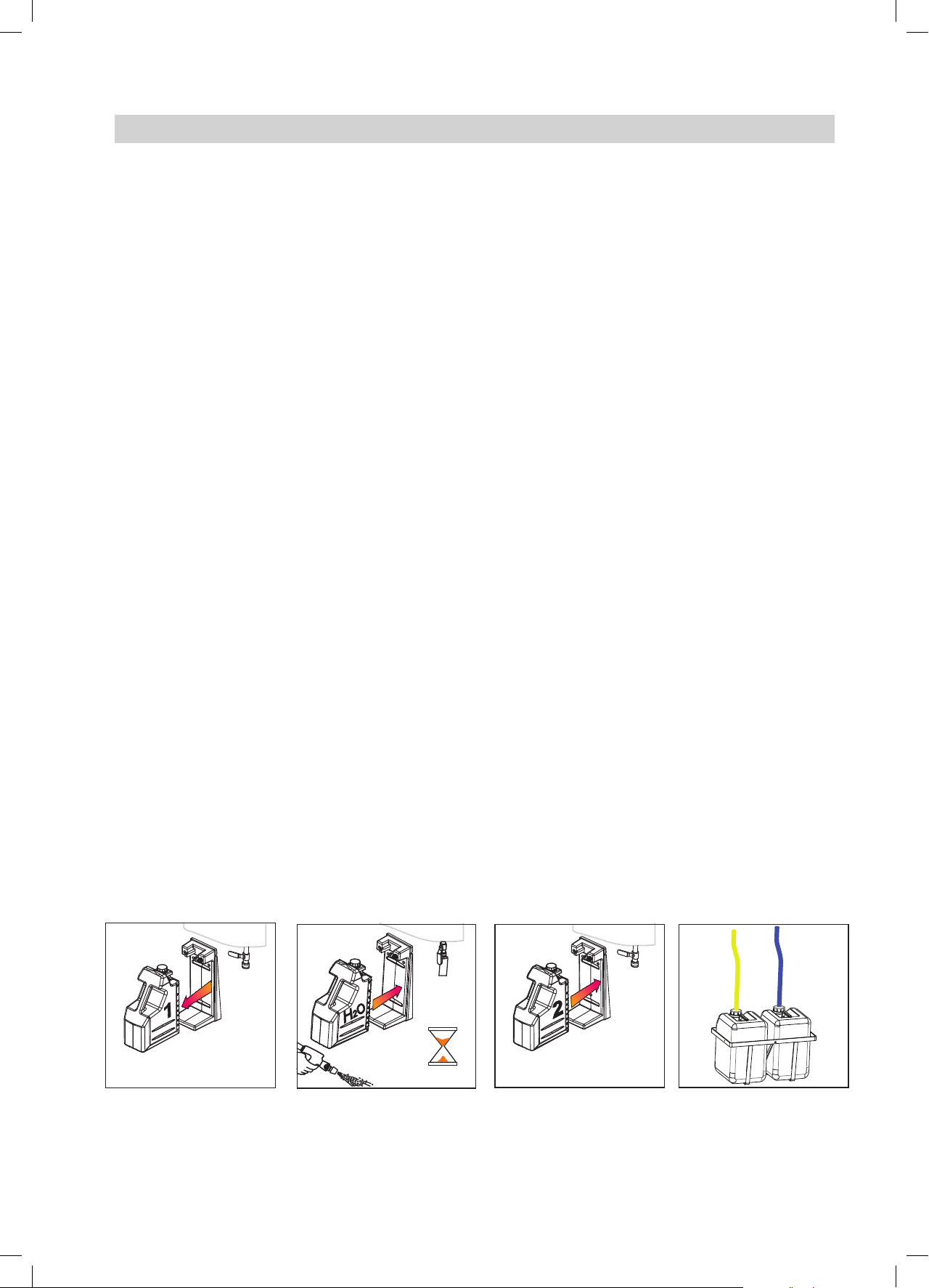
2.3 Connection of Detergents ............................ 4
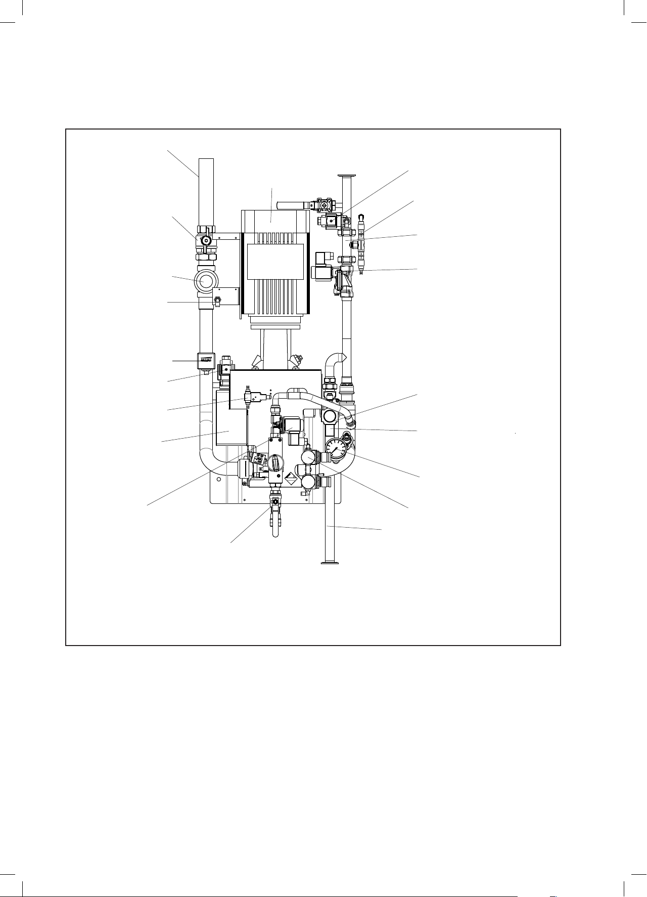
2.4 Layout Drawing............................................ 5
3. Directions before Operation.................................8
3.0 Automatic Cleaning...................................... 8
3.1 Function of User Pack System (accessory). 8
3.2 Bleeding the pump.........................................8
4. Manual Cleaning................................................. 9
4.0 Principle of the Injector System, Satellite .... 9
4.0.1 Functional principle of rinsing ............ 9
4.0.2 Functional principle of foaming.......... 9
4.1 Nozzle- and Handle Position ....................... 9
5. Security Devices............................................... 10
6. Regular Control and Service ............................ 10
7. Trouble shooting and Remedy.......................... 11
8. Flow Diagram ................................................... 13
8.1 Electric Diagram...........................................16
............................................ 17
10. Technical Data .................................................. 18
11. Guarantee......................................................... 19
12. Manufacturer ................................................... 19
Sparepart list............................................................79
Table des matières FR
1. Préface ......................................................... 44
2. Raccordement au circuit de basse pression..... 45
2.0 Instructions de montage ............................ 45
2.1 Raccordement de l’eau.............................. 45
2.2 Branchement d’air comprimé..................... 45
2.3 Alimentation en produits de nettoyage ...... 45
2.4 Dessin de disposition................................. 46
3. A lire avant l’utilisation ...................................... 49
3.0 Nettoyage automatique.............................. 49
3.1 Fonctionnement du système User Pack
(accessoire) ............................................... 49
3.2 Purge de la pompe........................................49
4. Nettoyage manuel ............................................ 50
4.0 Principe du système d’injecteur, satellite ... 50
4.0.1 Fonctionnement du rinçage ............. 50
4.0.2 Fonctionnement du moussage ........ 50
4.1 Positions des buses et de la poignée ........ 50
5. Dispositifs de sécurité....................................... 51
6. Révision et entretien réguliers .......................... 51
7. Diagnostic et résolution des pannes................. 52
8. Diagramme de fonctionnement ........................ 54
9. Plaque signalétique .......................................... 58
10. Données techniques......................................... 59
11. Garantie ......................................................... 60
12. Fabricant ......................................................... 60
Sparepart list............................................................79
Indice ES
1. Introducción ...................................................... 62
2. Conexiones al sistema de baja presión............ 63
2.0 Instrucciones de montaje........................... 63
2.1 Alimentación de agua ................................ 63
2.2 Alimentación de aire comprimido............... 63
2.3 Alimentación de detergentes ..................... 63
2.4 Diagrama ................................................... 64
3. Instrucciones previas al uso ............................. 67
3.0 Limpieza automática.................................. 67
3.1 Función del sistema User Pack
(accesorio) ................................................. 67
3.2 Purge de la Bomba.....................................67
4. Limpieza manual .............................................. 68
4.0 Principio del sistema inyector, Satélite ...... 68
4.0.1 Principio de operación durante el
enjuague.......................................... 68
4.0.2 Principio de operación durante el
espumado........................................ 68
4.1 Posición de la boquilla y del mango .......... 68
5. Dispositivos de seguridad................................. 69
6. Control periódico y mantenimiento ................... 69
7. Localización y reparación de averías ............... 70
............................................. 72
...................................... 76
10. Datos técnicos .................................................. 77
11. Garantía ......................................................... 78
12. Fabricante ........................................................ 78
Sparepart list............................................................79
Inhaltsverzeichnis DE
1. Vorwort ......................................................... 26
2. Anschluss an die Niederdruckanlage ............... 27
2.0 Montage der Anlage................................... 27
2.1 Wasseranschluss.............................................. 27
2.2 Druckluftanschluss..................................... 27
2.3 Reinigungsmittelanschluss ........................ 27
2.4 Übersichtszeichnung ................................. 28
3. Anleitung vor Inbetriebnahme........................... 31
3.0 Automatische Reinigung............................ 31
3.1 Kanisterhaltersystem (Zubehör) ................ 31
3.2 Entlüften der Pumpe...................................31
4. Manuelle Reinigung.......................................... 32
4.0 Prinzip des Kanisterhaltersystems,
Satellit ........................................................ 32
4.0.1 Spülen Prinzip.................................. 32
4.0.2 Schaum Prinzip................................ 32
.................... 32
5. Sicherheitseinrichtungen .................................. 33
6. Regelmäßige Wartungsarbeiten
und Prüfungen .................................................. 33
7. Betriebsstörungen und Abhilfe.......................... 34
8. Strömungsdiagramm ........................................ 36
9. Typenschild....................................................... 40
10. Technische Daten ............................................. 41
11. Garantiebedingungen ....................................... 42
12. Hersteller ......................................................... 42
Sparepart list............................................................79

3
Nilsk FOOD
Pegasus M-Series
Declaration of Conformity Konformitätserklärung
Déclaration de Conformité Dichiarazione di Conformità
Declaración de Conformidad Declaração de Conformidade
Δήλωση Συμμόρφωσης Overeenkomstigheidsverklaring
Försäkran om överensstämmelse Vaatimustenmukaisuusvakuutus
Overensstemmelseserklæring Deklaracja zgodności
Декларация осоответствии Megfelelőségi nyilatkozat
Izjava o skladnosti Izjava o usklađenosti
Deklaracija o konformitetu Declaraţie de Conformitate
Декларация за съответствие Prohlášení o shodě
Prehlásenie o konformite Uygunluk Bildirgesi
Vastavusdeklaratsioon Atitikties deklaracija
Paziņojums par atbilstību prasībām Свідчення про відповідність вимогам
Nilsk FOOD
Blytækkervej 2
9000 Aalborg
Danmark

Declaration of Conformity
products PZC, to which this declaration relates, are in conformity with
these Council directives on the approximation of the laws of the EC
menber states:
Function: Automatic hygiene Station
Model/Type: PZC-M1, PZE-M2, CIP-M3
Serial number: All
Machinery Directive (2006/42/EC:2006-05-17).
Standard used: EN 60335-2-79:2009
Standard used: EN 12100-1/A1:2009 and EN 12100-2/A1:2009.
Konformitätserklärung
PZC, in Übereinstimmung mit den Richtlinien zur Angleichung der
Rechtsvorschriften der Mitgliedstaaten ist:
Funktion: Automatische hygiegne Station
Modell/Typ: PZC-M1, PZE-M2, CIP-M3
Seriennummer: Alle
Maschinendirektive (2006/42/EC:2006-05-17).
Standarden: EN 60335-1: 2012
Standarden: EN 12100-1/A1:2009 and EN 12100-2/A1:2009.
Déclaration de conformité
que les produits PZC, auxquels se réfère cette déclaration, sont
conformes à ces directives du Conseil sur le rapprochement des
législations des États membres :
Fonction : Station d’hygiène automatique
Modèle/Type : PZC-M1, PZE-M2, CIP-M3
Numéro de série : Tous
Directive 2006/42/CE du 17 mai 2006 relative aux machines
Normes appliquées : EN 60335-1: 2012
Normes appliquées : EN 12100-1/A1:2009 and EN 12100-2/A1:2009.
Dichiarazione di conformità
prodotti PZC, ai quali fa riferimento la presente dichiarazione, sono
conformi alle direttive del Consiglio concernenti il riavvicinamento
delle legislazioni degli stati membri della UE:
Funzione: Igiene Stazione automatica
Modello/Tipo: PZC-M1, PZE-M2, CIP-M3
Numero di serie: Tutti
Direttiva Macchine (2006/42/CE:2006-05-17).
Standard utilizzato: EN 60335-1: 2012
Standard utilizzato: EN 12100-1/A1:2009 and EN 12100-2/A1:2009.
Declaración de conformidad
responsabilidad que los productos PZC,
declaración cumplen con las directivas de este Consejo sobre la
legislación de los estados miembros de la CE:
Función: Estación automática de higiene
Modelo/tipo: PZC-M1, PZE-M2, CIP-M3
All
Directiva sobre máquinas (2006/42/EC:2006-05-17).
Normativa usada: EN 60335-1: 2012
Normativa usada: EN 12100-1/A1:2009 and EN 12100-2/A1:2009.
Declaração de Conformidade
os produtos PZC, referidos nesta declaração, se encontram
em conformidade com estas diretivas do Conselho relativas à
aproximação das disposições legislativas dos Estados-Membros da
CE:
Função: Estação automática higiene
Modelo/Tipo: PZC-M1, PZE-M2, CIP-M3
Diretiva relativa às máquinas (2006/42/CE:2006-05-17).
Norma utilizada: EN 60335-1: 2012
Norma utilizada: EN 12100-1/A1:2009 and EN 12100-2/A1:2009.

Δήλωση συμμόρφωσης
PZC
PZC-M1, PZE-M2, CIP-M3
:
EN 60335-1: 2012
EN 12100-1/A1:2009 and EN 12100-2/
A1:2009.
Verklaring van overeenstemming
dat de producten PZC, waarop deze verklaring betrekking heeft,
in overeenstemming zijn met de volgende Richtlijnen van de Raad
EG-lidstaten:
Functie: Automatisch hygiëne station
Model/Type: PZC-M1, PZE-M2, CIP-M3
Serienummer: Alle
Machinerichtlijn (2006/42/EG:17-05-2006).
Toegepaste norm: EN 60335-1: 2012
Toegepaste norm: EN 12100-1/A1:2009 and EN 12100-2/A1:2009.
Försäkran om överensstämmelse
PZC, som omfattas av denna försäkran, är i överensstämmelse med
rådets direktiv om tillnärmning av medlemsstaternas lagstiftning i EG:
Funktion: Automatisk hygien station
Modell/typ: PZC-M1, PZE-M2, CIP-M3
Serienummer: Alla
Maskindirektiv (2006/42/EC:2006-05-17).
Standard som används: EN 60335-1: 2012
Standard som används: EN 12100-1/A1:2009 and EN 12100-2/
A1:2009.
Vaatimustenmukaisuusvakuutus
PZC, jota tämä vakuutus koskee, noudattavat direktiivejä, jotka
käsittelevät EY:n jäsenvaltioiden lakien yhdenmukaisuutta koskien
seuraavia:
Toiminto: Automaattinen hygienia-asema
Malli/tyyppi: PZC-M1, PZE-M2, CIP-M3
Sarjanumero: Kaikki
Konedirektiivi (2006/42/EY:2006-05-17).
Käytetty standardi: EN 60335-1: 2012
Käytetty standardi: EN 12100-1/A1:2009 and EN 12100-2/A1:2009.
Overensstemmelseserklæring
Funktion: Automatisk hygiegne station
Model/Type: PZC-M1, PZE-M2, CIP-M3
Serienummer: Alle
Maskindirektiv (2006/42/EC:2006-05-17).
Standarder: EN 60335-1: 2012
Standarder: EN 12100-1/A1:2009 and EN 12100-2/A1:2009.2008
Deklaracja zgodności
Funkcja: Automatyczna stacja higieny
Model/typ: PZC-M1, PZE-M2, CIP-M3
Numer seryjny: Wszystkie
Dyrektywa Maszynowa (2006/42/EC:2006-05-17).
Stosowana norma: EN 60335-1: 2012
Stosowane normy: EN 12100-1/A1:2009 and EN 12100-2/A1:2009.
Декларация соответствия
PZC,
:
PZC-M1, PZE-M2, CIP-M3
:
EN 60335-1: 2012
EN 12100-1/A1:2009 and EN 12100-2/
A1:2009.
Megfelelőségi nyilatkozat
hogy a PZC, Amelyekre ez a nyilatkozat vonatkozik, megfelelnek az
irányelveknek:
Funkció: Automatikus higiénia station.
Modell/Típus: PZC-M1, PZE-M2, CIP-M3
Sorozatszám: Összes
Gépekre vonatkozó irányelv (2006/42/EC:2006-05-17).
Alkalmazott szabvány: EN 60335-1: 2012
Alkalmazott szabvány: EN 12100-1/A1:2009 and EN 12100-2/
A1:2009.

Izjava o skladnosti
izdelki PZC, na katere se nanaša ta deklaracija, skladni z naslednjimi
Funkcija: Samodejno higiena postaja
Model/tip: PZC-M1, PZE-M2, CIP-M3
Serijska številka: Vse
Direktiva o strojih (2006/42/ES:2006-05-17).
Uporabljeni standardi: EN 60335-1: 2012
Uporabljeni standardi: EN 12100-1/A1:2009 and EN 12100-2/
A1:2009.
Izjava o usklađenosti
proizvodi PZC,
zajednice:
Funkcija: Automatski higijena stanica.
Model/vrsta: PZC-M1, PZE-M2, CIP-M3
Serijski broj: Svi
Izjava o strojevima (2006/42/EC:2006-05-17).
Primijenjena norma: EN 60335-1: 2012
Primijenjena norma: EN 12100-1/A1:2009 and EN 12100-2/A1:2009.
Deklaracija o konformitetu
Funkcija: Automatska higijenska stanica
Model/tip: PZC-M1, PZE-M2, CIP-M3
serijski broj: Kompletna
Direktiva o mašinama (2006/42/EC:2006-05-17).
Primenjen standard: EN 60335-1: 2012
Primenjen standard: EN 12100-1/A1:2009 and EN 12100-2/A1:2009.
PZC,
statelor membre CE:
Model/Tip: PZC-M1, PZE-M2, CIP-M3
toate
Standarde utilizate: EN 60335-1: 2012
Standarde utilizate: EN 12100-1/A1:2009 and EN 12100-2/A1:2009.
Декларация за съответствие
PZC,
PZC-M1, PZE-M2, CIP-M3
EN 60335-1: 2012
EN 12100-1/A1:2009 and EN 12100-2/
A1:2009.
Prohlášení o shodě
PZC, na které se toto prohlášení vztahuje, vyhovují
Funkce: Automatické hygienická stanice
Model/Typ: PZC-M1, PZE-M2, CIP-M3
Všechna
EN 60335-1: 2012
EN 12100-1/A1:2009 and EN 12100-2/A1:2009.

Prehlásenie o zhode
PZC,
Funkcia: Automatické hygienickej stanice
Model/typ: PZC-M1, PZE-M2, CIP-M3
Všetky
EN 60335-1: 2012
EN 12100-1/A1:2009 and EN 12100-2/A1:2009.
Uygunluk Beyanı
uygundur:
PZC-M1, PZE-M2, CIP-M3
EN 60335-1: 2012
EN 12100-1/A1:2009 and EN 12100-2/
A1:2009.
Vastavusdeklaratsioon
“ PZC”, mille kohta käesolev deklaratsioon kehtib, vastavad nõukogu
direktiividele ELi liikmesriikide õigusaktide ühtlustamise kohta:
Funktsioon: Automaatne hügieeni jaam
Mudel/tüüp: PZC-M1, PZE-M2, CIP-M3
Seerianumber: kõik
Masinadirektiiv (2006/42/EÜ:2006-05-17).
Kasutatav standard: EN 60335-1: 2012
Kasutatav standard: EN 12100-1/A1:2009 and EN 12100-2/A1:2009.
Atitikties deklaracija
Paskirtis: Automatinis higienos stotis
Modelis / tipas: PZC-M1, PZE-M2, CIP-M3
Serijos numeris: visi
taikytas standartas: EN 60335-1: 2012
taikytas standartas: EN 12100-1/A1:2009 and EN 12100-2/A1:2009.
Atbilstības deklarācija
PZC,
Funkcija: .
Modelis/tips: PZC-M1, PZE-M2, CIP-M3
visi.
Izmantotais standarts: EN 60335-1: 2012
Izmantotais standarts: EN 12100-1/A1:2009 and EN 12100-2/
A1:2009.
Свідчення про відповідність вимогам
PZC,
PZC-M1, PZE-M2, CIP-M3
EN 60335-1: 2012
EN 12100-1/A1:2009 and EN 12100-2/
A1:2009.
Flemming Asp
Blytaekkervej 2
9000 Aalborg, Denmark
Signature:
Flemming Asp
R & D Manager
Aalborg d. 01-01-2016

8
Nilsk FOOD
1. Preface
hygiene requirements.
use. On operation as laid down in the directions for use you will achieve optimum cleaning and hygiene in your
factory and minimum requirement for maintenance and repair work.
a) - foam spreading of detergents
Read before Use
Wear glasses when using the unit.
Wear gloves and suitable clothing when using the unit.
Note:
A potentially damaging situation.
Possible consequences: The product or something in its vicinity could be damaged. Prevention.
Caution:
A dangerous situation.’Possible consequences: light or minor injuries. Can also be used in warn
against damage to property or other goods prevention.
Warning:
A Potentially dangerous situation.
Possible consequences: Death or severe injury Prevention.
Danger:
A dangerous situation.’Possible consequences: Death or severe injury Prevention.
Danger:
EN

9
Nilsk FOOD
2. Connections to the Low Pressure System
2.0 Directions for Mounting
The system must be mounted in
frost-free rooms only.
2.1 Water Connection
a) Prior to connection to the sys-
tem the supply pipe should be
rinsed through carefully in order
to remove coarse impurities
and metal shavings.
b) The water connections for the
pump station are at the top
of the system (item 2 on the
layout drawing on page 10-12).
c) It is important to ensure abun-
dant water - no less than 150 l/
min. per pumping unit. To meet
this requirement the diameter
of the supply pipe should be
minimum 1 1/4" (32 mm) at a
water pressure of 3,5 bar, and
at a water pressure lower than
3,5 bar the water pipe should
be minimum 1 1/2" (38 mm).
d) The system is equipped with a
pump.
e) The pressure loss in the supply
pipe should be kept as low as
possible which means that:
- unnecessarily long supply
pipes should be avoided
- low-resistant ball valves
should be used
loss should be avoided..
f) On pipe mounting care should
be taken that no air locks are
produced.
g) Max. allowed temperature of
inlet water: 70°C.
h) Max. allowed pressure of inlet
water for the pump station: 4
bar.
2.2 Compressed-Air
Connection
a) Prior to connection to the
system the supply pipe should
be rinsed through carefully with
air in order to remove coarse
impurities and metal shavings.
b) The system should be con-
nected to a compressed-air
- an inlet pressure to the low-
pressure system of minimum
5 bar
- a minimum capacity of 500
l/min.
c) The compressed-air pipe
should be connected direct to
the system by a union to facili-
tate dismounting. All systems
are equipped with a drainable
closing valve with 1/4" thread
(compressed-air connection
for the pump station) (1 on the
layout drawing on page 10-12).
2.3 Connection of Detergents
The supply of detergents are
either supplied from the User Pack
System, which can be delivered as
also be established through piping
systems. (page 13).
Blue hose for alkalic product and
yellow hose for chlorine/acid prod-
uct.
CAUTION!
When changing between dier-
ent products in the User Pack
system, these must be rinsed
thoroughly with clean water.
>20 sec.
H20 H20
110003485

10
Nilsk FOOD
13
24
19
5
6
17
25
14
4
42
20
12
1
11
10
2
30
22
23
25
PZC-M1
1. Air inlet
2. Inlet pipe
4. Outlet water
5. Electrical box
6. Outlet manual system
10. Ball valve for water
11. Strainer
12. Flow switch
13. Pump
14 Pressure gauge
17. Solenoid valve, rinse water
19. Solenoid valve, detergent
20. Injector, M1
22. Solenoid valve, air
23 Non return valve, chemicals
25. Solenoid valve, manual cleaning
30. Filter/press. gauge/reduction valve, air
37. Block manual cleaning
42 Solenoide valve, chemicals
119000372-1

11
Nilsk FOOD
PZE-M2
13
17
25
14
30
37
6
5
19
24
12
1
11
10
2
21
42
22
23
1. Air inlet
2. Inlet pipe
5. Electrical box
6. Outlet manual system
10. Ball valve for water
11. Strainer
12. Flow switch
13. Pump
14 Pressure gauge
17. Solenoid valve, rinse water
19. Solenoid valve, detergent
21. Injector, M2+M3
22. Solenoid valve, air
23 Non return valve, chemicals
25. Solenoid valve, manual cleaning
30. Filter/press. gauge/reduction valve, air
37. Block manual cleaning
42 Solenoid valve, chemicals
119000372-2

12
Nilsk FOOD
2
13
17
12
18
1
11
10
25
30
14
6
22
19
24
5
37
42
21
23
CIP-M3
1. Air inlet
2. Inlet pipe
5. Electrical box
6. Outlet manual system
10. Ball valve for water
11. Strainer
12. Flow switch
13. Pump
14. Pressure gauge
17. Solenoid valve, rinse water
18. Solenoid valve, disinfectant
19. Solenoid valve, detergent
21. Injector, M2+M3
22. Solenoid valve, air
23. Non return valve, chemicals
25. Solenoid valve, manual cleaning
30. Filter/press. gauge/reduction valve, air
37. Block manual cleaning
42. Solenoid valv, chemicals
119000372-3

13
Nilsk FOOD
Limiting Nozzle
3. Directions before Operation
3.0 Automatic Cleaning
NOTE! Seperata sanitising is only
available on model CIP-M3.
a) The unit is equipped with
limiting nozzles placed in non
return valves for detergent on
the injector.
b) Start the automatic system
from the control unit by means
of the entered program.
c) Set the air pressure at 5 bar
on the reducing valve for air.
Check the air pressure on the
pressure gauge for air .
NOTE! When setting the reduc-
ing valve for air carefully pull up
the knob and turn it right for higher
pressure and left for less pressure.
d) The foam quality is correct
when the foam is a little moist
and small bubbles are created.
Being to wet the foam will slide
utilisation of the detergent.
caused by
- too low concentration of the
detergent
- too high temperature of the
inlet water
pressure
- detergent not suitable
3.1 Function of User Pack
System (accessory)
Principle of operation
The User Pack is pushed into the
holder under the unit.
The level of Ecolab product is indi-
cated on the outside level tube.
CAUTION!
When changing between different products
in the User Pack cans, these have to be
rinsed thoroughly with clean water. Further,
the injector is also to be rinsed.
3.2 Bleeding the pump
1. Loosen the relief plug (A) 1-2
revolutions until water and air
Never loosen the relief
plug while the pump
is running as this may
damage the packing.
2. Tighten the relief plug again
3. Start the pump so that all re-
maining air pockets are forced
up to the top of the pump.
4. Stop the pump
5. Loosen the relief plug 1-2
revolutions again and bleed
the system until only water
6. Tighten the relief plug once
more
The unit is now ready for operation.
DETAIL A
A
110003485

14
Nilsk FOOD
4. Manual cleaning
4.0 Principle of the injector
system, Satellite
The system consists of a manually
controlled change-over-block with
a built-in injector, dosing valve,
external non-return valve for deter-
gents and air.
The principle is that the operation
handle closes for the rinsing and
forces the water through the injec-
tor.
Air will be added when handle is
in either foam or foam sanitising
position.
4.0.1 Functional principle of
rinsing
During rinsing the operation handle
is positioning so the water passes
directly through the block and out
in the rinsing hose. In this posi-
tion the injector for products will
automatically be rinsed with clean
water. When the low-pressure gun
is open, the pump station automati-
cally starts after approx. 5 seconds
and thereby rinsing pressure is
achieved.
4.0.2 Functional principle of
foaming
During foaming the operation
handle is positioning so the water
forced to pass through the injec-
tor in the block. When the low-
pressure gun is open the pump
station starts up automatically after
approx. 5 seconds. The water will
then be led through the injector,
which sucks up products into the
mixing chamber where it is mixed
with air and water to the required
solution.
4.1 Nozzles and Handle
Position
Rinse
The hose is connected to the
right outlet. Push/pull the twin
nozzle in rinse position. Operation
handle is in rinsing position.
Foam
The hose is connected to the out-
let. Push/pull the twin nozzle in
foam position. Operation handle is
in foaming position.
Sanitizing
The hose is connected to the right
outlet. Push/pull the twin nozzle in
rinse position.Operation handle is
in foam sanitising position.

15
Nilsk FOOD
5. Security Devices
a) Closing valve for water (10 on
layout drawing pages 10-12).
On the inlet pipe there is a
closing valve in the cabinet by
which the water supply to the
pump can be closed.
b) Strainer (11 on layout drawing
pages 10-12).
On the inlet pipe of the pump a
strainer is mounted to prevent
impurities from the water and
the pipe work to get into the
injector.
c) Flow switch (12 on layout
drawing pages 10-12).
switch has been mounted on
activates the pump as soon as
switch. If all valves are closed
connects the pump after the
time interval entered into the
control.
On the outlet pipe a non-return
valve is mounted to prevent a
d) Drainable closing valve for air
(1 on the layout drawing on
pages 10-12)
A manual closing valve for air
is mounted on the air inlet for
closing the air supply.
e) Solenoid valve for air (22 on
the layout drawing on pages
10-12).
The air supply for the injector in
the automatic part is opened by
solenoid valve.
f) Pressure gauge and reduction
valve for air (30 on layout on
pages 10-12).
6. Regular Control and Service
To prevent errors and accidents on use of the equipment the system should at least once a year be checked by
knowledge of low-pressure cleaners or similar equipment and who are familiar with the state work security regu-
lations, accident preventing regulations, lines and generally acknowledged technical regulations such as DIN-
norms and VDE-provisions. We refer in this connection to our service department:
DK-9000 Aalborg
Tel. + 45 72 18 21 00
Fax + 45 72 18 20 99

16
Nilsk FOOD
Symptoms
The system does not start
The system does not build up
pressure
Unstable pump pressure
No foam creation
The system sucks no
detergent
Possible causes Remedy
Fuse blown Replace fuse
Fuse in control box blown Replace fuse
Motor overload disconnected Search error
No water supply Ensure water supply
Incorrect direction of rotation
of pump Connect the pump correctly
Flow switch defective Call for skilled persons
Ensure water supply
Filter in inlet pipe blocked up
Detergent unsuited Choose suited detergent
Ensure air supply
Too high air pressure in
injector Adjust air supply
Incorrect nozzle mounted Contact JBT
No air supply Ensure air supply
Filter for detergent blocked up
Non-return valve blocked up Clean injector
7. Shooting and Remedy
Measures at trouble shooting

17
Nilsk FOOD
Fault Cause Remedy
The machine does not start Fuse blown
Power supply fault
Fuse in the wiring box of the
machine blown.
Motor overload in the wiring box of
machine disconnected.
Check fuse and replace, if necessary
Power supply to be checked by an
expert.
Check fuse and replace, if necessary.
Before switching on again, check
cause of disconnection.
The machine does not build up
pressure.
The program does not function
correctly.
No water supply.
Direction of rotation of the pump is
not correct.
Check the program.
Please call for assistance by JBT
Open inlet valve of machine.
Change direction of rotation of pump
in accordance with arrow on pump.
Unstable or too low pump
pressure.
Strainer on inlet pipe blocked up.
1/4" piping.
Unsatisfactory foam quality. Detergent not suitable.
Too low concentration of the
detergent.
Too high temperature of teh inlet
water.
pressure.
Change to correct type of detergent.
2-4%.
Reduce the temperature of the water.
min., 5 bar.
Spreading of foam is not
uniform.
Incorrect air pressure on the
system.
Too high air pressure in the injector
(read pressure on pressure gauge.
Incorrect nozzles mounted.
min., 5 bar.
Set pressure on 5 bar on the
regulating valve.
Set pressure on 5 bar on the
regulating valve.
Contact JBT for instructions.
No spreading of foam. The program does not function
correctly.
The non-return valve in the injector
is blocked up.
Check the program. Call for JBT as-
sistance, if necessary.
Clean or replace the valve.
No pressure air in the system. Inlet valve for pressure air is not
open.
The solenoid valve for pressure air is
blocked up or defective.
Open inlet valve for pressure air.
Clean or replace the solenoid valve.

18
Nilsk FOOD
(button)
Water outlet
Water inlet
Detergent
Air inlet
31
14
10
24
M
16
17
11 12 13 15
23
30
Foam
42 21
22
28
27
32
F
19
29
PZC-M1
8. Flow diagram
10. Ball valve, water
11. Strainer
12. Flow switch
13. Pump
14 Pressure gauge
15. Non-return valve, water
17. Solenoid valve, rinse water
19. Solenoid valve, detergent
21. Injector
22. Solenoid valve, air
23. Non-return valve chemicals
27. Injecting air
28. Non-return valve, air
29. Filter for detergent
30. Pressure gauge/reduction valve, air
31. Non-return valve, air
32. Ball valve, with drain, air, with blow out
42. Solenoid valve, chemicals

19
Nilsk FOOD
21
27
Water outlet/Foam
16
23 22
24
30
28
Deterg.
42
25
30
Water inlet
Foam outlet
Manual cleaning
Air inlet
32
31
37
Disinfectant
19
38
29 29
14131110 15
M
17
12
F
PZE-M2
10. Ball valve, water
11. Strainer
12. Flow switch
13. Pump
14 Pressure gauge
15. Non-return valve, water
17. Solenoid valve, rinse water
19. Solenoid valve, detergent
21. Injector
22. Solenoid valve, air
23. Non-return valve chemicals
25. Solenoid valve, manual cleaning
27. Injecting air
28. Non-return valve, air
29. Filter for detergent
30. Pressure gauge/reduction valve, air
31. Non-return valve, air
32. Ball valve with drain, air, with blow out
37. Block manual cleaning
38. Outlet manual cleaning
42 Solenoid valve, chemicals

20
Nilsk FOOD
21
27
Water outlet/Foam
16
23 22
24
30
28
Deterg.
42
25
30
Water inlet
Foam outlet
Manual cleaning
Air inlet
32
31
Disinfectant
1918
38
37
2929
14
23
131110 15
M
17
12
F
CIP-M3
10. Ball valve, water
11. Strainer
12. Flow switch
13. Pump
14 Pressure gauge
15. Non-return valve, water
17. Solenoid valve, rinse water
18 Solenoid Valve, desinfection
19 Solenoid valve, chemicals
21. Injector
22. Solenoid valve, air
23. Non-return valve chemicals
25. Solenoid valve, manual cleaning
27. Injecting air
28. Non-return valve, air
29. Filter for detergent
30. Filter/pressure gauge/reduction valve, air
31. Non-return valve, air
32. Ball valve with drain, air, with blow out
37. Block manual cleaning
38. Outlet manual cleaning
42. Solenoid valve, chemicals
Other manuals for PEGASUS PZC-M1
1
This manual suits for next models
2
Table of contents
Languages:
Other Nilfisk-Advance Industrial Equipment manuals
Popular Industrial Equipment manuals by other brands

ABB
ABB HT616345 Operation manual

hager
hager UZ1LA1 Series Mounting instructions

AGC
AGC pro3 Operation and installation manual

DROPSA
DROPSA MiQueL EXT Operating and maintenance manual

Wilo
Wilo WiBooster Installation and operating instructions

Metal Work Pneumatic
Metal Work Pneumatic SVAK 200 Use and maintenance