Metallkraft GS 1100-16 E User manual
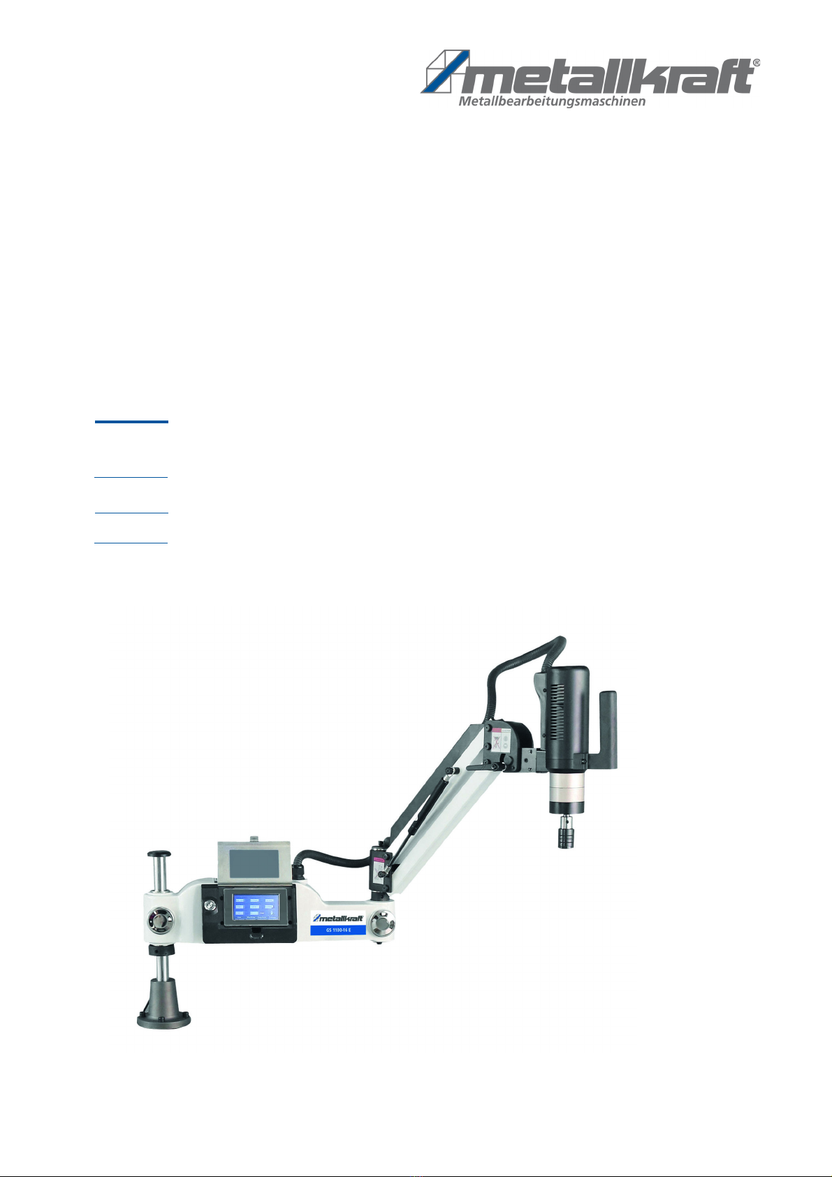
GS 1100-16 E
Operating instructions
GS 1200-24 E
Thread Tapping Machine
GS-E SERIES
GS 1100-16 E
GS 1200-36 E

2 GS-E Series | Version 1.09
Imprint
Product identification
Thread Tapping Machine Ite nu ber
GS 1100-16 E 4450116
GS 1200-24 E 4450124
GS 1200-36 E 4450136
Manufacturer
Stür er Maschinen G bH
Dr.-Robert-Pfleger-Str. 26
D-96103 Hallstadt/Ba berg
Fax: 0049 (0) 951 96555 - 55
E-Mail: info@ etalkraft.de
Internet: www. etalkraft.de
Information on the operating instructions
Original operating instructions
according to DIN EN ISO 20607:2019
Edition: 14.12.2021
Version: 1.09
Language: English
Author: MS
Copyright information
Copyright © 2021 Stür er Maschinen G bH, Hallstadt,
Ger any.
Technical changes and errors excepted.
Content
1 Introduction ............................................................. 3
1.1 Copyright ............................................................ 3
1.2 Custo er service................................................ 3
1.3 Li itation of liability............................................. 3
2 Safety ....................................................................... 3
2.1 Sy bol explanation ............................................ 3
2.2 Obligations of the operating co pany ................ 4
2.3 Personnel require ents...................................... 5
2.4 Personal protective equip ent ........................... 5
2.5 Safety labels on the thread tapping achine...... 6
2.6 Safety devices .................................................... 6
2.7 Safety data sheets.............................................. 6
2.8 Special safety rules for the thread tapping
achine .............................................................. 6
3 Intended Use............................................................ 7
3.1 Reasonably foreseeable isuse......................... 7
3.2 Residual risks ..................................................... 7
4 echnical Data......................................................... 7
4.1 Table................................................................... 7
4.2 Type plate........................................................... 8
5 ransport, packaging, storage............................... 8
5.1 Delivery............................................................... 8
5.2 Transport ............................................................ 8
5.3 Packaging........................................................... 8
5.4 Storage ............................................................... 8
6 Description of device.............................................. 9
6.1 Representation ................................................... 9
7 Assembly ................................................................. 9
7.1 Setting the tapping direction ............................. 10
7.2 Electrical connection......................................... 10
8 Operation ............................................................... 11
8.1 Operation.......................................................... 11
8.2 Turn on/off ........................................................ 12
8.3 User interface ................................................... 12
8.4 Language settings ............................................ 13
8.5 Deep hole operation ......................................... 13
8.6 Storage and recall of workpiece para eters .... 13
8.7 User para eter................................................. 13
8.8 User para eter for lubricating and scrap
blowing.............................................................. 14
8.9 Adjusting the coupling torque of the collet
chuck ................................................................ 14
9 Cleaning, maintenance and repair....................... 14
9.1 Cleaning and aintenance............................... 14
9.2 Overhaul of the fuse ......................................... 15
9.3 Repair ............................................................... 15
10 Disposal, recycling of old equipment ............... 15
10.1 Deco ission ............................................... 15
10.2 Disposal of electrical equip ent.................... 15
10.3 Disposal via unicipal collection points......... 15
10.4 Disposal of lubricants..................................... 15
11 roubleshooting.................................................. 16
12 Spare parts .......................................................... 17
12.1 Ordering spare parts...................................... 17
12.2 Spare parts drawing....................................... 18
13 Wiring Diagram Control Unit.............................. 20
14 EC-Declaration of Conformity............................ 21

Introduction
GS-E Series | Version 1.09 3
1 Introduction
With the purchase of the METALLKRAFT threading a-
chine you have ade a good choice.
Read the operating instructions carefully before
commissioning.
This is an i portant co ponent and ust be kept close
to the achine and accessible to all users.
The operating instructions infor you about the correct
co issioning, the intended use as well as the safe and
efficient operation and aintenance of the thread cutting
achine
In addition, observe the local accident prevention regula-
tions and general safety regulations for the area of appli-
cation of the thread cutting achine
1.1 Copyright
The contents of these instructions are protected by copy-
right. Their use is per itted within the fra ework of the
use of the thread cutting achine. Any further use is not
per itted without the written consent of the anufactu-
rer. Forwarding and copying of this docu ent, utilization
and co unication of its contents are prohibited unless
expressly per itted. Infringe ents oblige you to pay da-
ages. To protect our products, we report trade arks,
Patent and design rights, if this is possible in individual
cases. We strongly oppose any infringe ent of our intel-
lectual property.
1.2 Customer service
Please contact your specialist dealer if you have any
questions about your threading achine or for technical
infor ation. They will be happy to help you with expert
advice and infor ation.
Germany:
Stür er Maschinen G bH
Dr.-Robert-Pfleger-Str. 26
D-96103 Hallstadt
Repair service:
Fax: 0049 (0) 951 96555-111
E-Mail: service@stuer er- aschinen.de
Spare part order:
Fax: 0049 (0) 951 96555-119
E-Mail: ersatzteile@stuer er- aschinen.de
We are always interested in infor ation and experiences
that result fro the application and can be valuable for
the i prove ent of our products.
1.3 Limitation of liability
All infor ation and notes in the operating instructions
have been co piled taking into account the applicable
standards and regulations, the state of the art and our
any years of knowledge and experience. The anufac-
turer accepts no liability for da age in the following ca-
ses:
- Non-observance of the operating instructions,
- Non-intended use,
- Use of inexperienced personnel,
- Unauthorized odifications,
- Technical odifications,
- Use of non-approved spare parts.
The actual scope of delivery ay deviate fro the expla-
nations and representations described here in the case
of special versions, when additional order options are
used or due to the latest technical changes.
The obligations agreed in the delivery contract, the gene-
ral ter s and conditions as well as the delivery conditi-
ons of the anufacturer and the legal regulations valid at
the ti e of the conclusion of the contract shall apply.
2 Safety
This paragraph will give you an overview of all i portant
safety packages for the protection of the people using it
well as for a safe and undisturbed operation. Other task-
based safety notes are included in the individual chap-
ters.
2.1 Symbol explanation
Safety instructions
The safety notes in these operating instructions are high-
lighted by sy bols. The safety notes are introduced by
signal words which express the concern of the risk.
4 GS-E Series | Version 1.09
Safety
ips and recommendations
It is necessary to observe the safety notes written in
these operating instructions in order to reduce the risk of
personal injuries and da ages to property.
2.2 Obligations of the operating com
pany
Operator
The operating co pany is the person who operates the
achine for business or co ercial reasons by herself,
or leaves it to a third party for use or application, and who
bears the legal product responsibility for the protection of
the user, the staff or for third parties.
Obligations of the operating company
If the aschine is used for co ercial purposes,
the operating co pany of the achine ust co ply with
the legal working safety regulations. Therefore, the
safety notes in this operating anual, as well as the
safety, accident prevention and environ ent protection
regulations applying for the area of application of the a-
chine ust be et. The following applies in particular:
- The operating co pany ust be infor ed about
the applying industrial safety regulations and fur-
ther analyse hazards resulting fro the special
working conditions at the place of use the achine.
She ust i ple ent these in for of operating
anuals for the operation of the achine.
- During the entire lifeti e of the achine, the oper-
ating co pany ust verify whether the operating
anuals prepared by her correspond to the current
status of the regulations, and ust adapt these if
necessary.
- The operating co pany ust una biguously regu-
late and deter ine the responsibilities for installa-
tion, operation, troubleshooting, aintenance and
cleaning.
- The operating co pany ust ensure that all per-
sons who work with the achine, have read and
understood this anual. Further ore she ust in-
struct the staff in regular intervals and infor the
about the hazards.
- The operator ust provide the necessary protec-
tive equip ent to the staff and order the use of the
necessary protective equip ent in a binding way.
Further ore the operating co pany is responsible to
keep the achine always in a technically flawless state.
Thus, the following applies:
- The operator ust ensure that the aintenance in-
tervals described in this anual are kept.
- The operator ust have all safety devices checked
regularly for their good working order and their in-
tegrity.
DANGER!
This co bination of sy bol and signal word indicates
an i inently hazardous situation which, if not avoi-
ded, will result in death or serious injury.
WARNiNG!
This co bination of sy bol and signal word indicates
a potentially hazardous situation which, if not avoi-
ded, will result in death or serious injury.
Caution!
This co bination of sy bol and signal word indicates
a potentially hazardous situation which, if not avoi-
ded, ay result in inor or oderate injury.
Attention!
This co bination of sy bol and signal word indicates
a possibly hazardous situation which, if not avoided,
ay result in da age to property and the environ-
ent.
NO E!
This co bination of sy bol and signal words indi-
cates a possibly dangerous situation which ay lead
to property and environ ental da ages if they are
not avoided.
ips and recommendations
This sy bol highlights useful tips and reco enda-
tions as well as infor ation for an efficient and trou-
ble-free operation.

Safety
GS-E Series | Version 1.09 5
2.3 Personnel requirements
Qualifications
The various tasks described in this anual place diffe-
rent de ands on the qualifications of the persons entrus-
ted with these tasks.
Only persons who can be expected to perfor this work
reliably are per itted to perfor any work. Persons
whose ability to react is influenced by drugs, alcohol or
edication, for exa ple, are not per itted.
In these operating instructions, the qualifications of the
persons listed below are na ed for the various tasks:
Operator
The operator has been instructed by the operator about
the tasks assigned to hi and possible dangers in case
of i proper behavior. The operator ay only perfor
tasks that go beyond operation during nor al operation
if this is specified in these operating instructions and the
operator has expressly entrusted hi with this task.
Qualified electrician
Due to their professional training, knowledge and expe-
rience as well as knowledge of the relevant standards
and regulations, the electrician is able to carry out work
on electrical syste s and to independently recognize
and avoid potential hazards.
The electrician is specially trained for the work environ-
ent in which he works and knows the relevant stan-
dards and regulations.
Specialist personnel
Due to their professional training, knowledge and expe-
rience as well as knowledge of the relevant standards
and regulations, the qualified personnel are able to carry
out the work assigned to the and to recognize possible
hazards independently and to avoid hazards.
Manufacturer
Certain work ay only be carried out by specialist per-
sonnel of the anufacturer. Other personnel are not aut-
horized to perfor this work. Contact our custo er ser-
vice depart ent to carry out any work that ay be
required.
2.4 Personal protective equipment
The personal protective equip ent is used to protect
persons against i pair ent of safety and health during
work. The personnel ust wear personal protective
equip ent during the various work on and with the de-
vice, which is referred to separately in the individual sec-
tions of these instructions.
The following section explains the personal protective
equip ent:
WARNING!
Danger in case of insufficient quali-
fication of persons!
Insufficiently qualified persons cannot assess the
risks when handling the tapping achine and expose
the selves and others to the risk of serious or fatal
injuries.
- All work ust be carried out by qualified personnel
only.
- Keep insufficiently qualified persons away fro the
work area.
Hearing protection
Hearing protection protects against hearing da age
caused by noise.
Head protection
The industrial hel et protects the head against fal-
ling objects and bu ping against fixed objects.
Face shield
The face shield protects the face fro flying parts.
Suitable protective gloves
The protective gloves protect the hands fro sharp-
edged co ponents, as well as fro friction, abrasi-
ons or deeper injuries.
Safety shoes
The safety shoes protect the feet fro crushing, fal-
ling parts and slipping on slippery surfaces.
Protective work clothing
Protective work clothing is tight-fitting clothing with
low tear resistance.
6 GS-E Series | Version 1.09
Safety
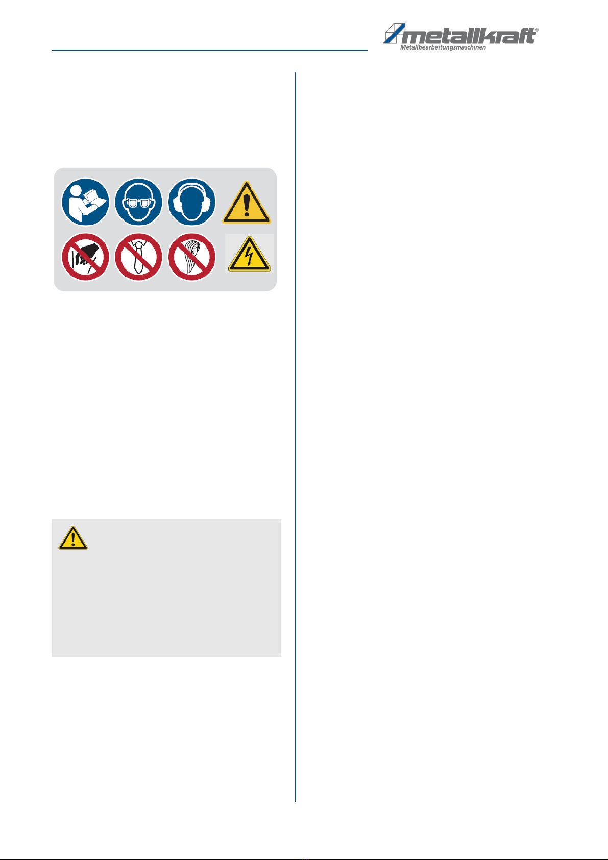
2.5 Safety labels on the thread tapping
machine
Various safety arkings are attached to the thread tap-
ping achine (Fig. 1), which ust be observed and follo-
wed:
Fig. 1: Safety labels - Mandatory sy bols: Read instructions for use,
Wear eye protection, Wear ear protection I Warning sy bols:
General warning sign | Electrical voltage I Prohibition sy bols:
Do not reach in, Do not wear a tie, Do not wear open hair
The safety arkings attached to the thread tapping a-
chine ust not be re oved. Da aged or issing safety
arkings can lead to incorrect actions, personal injury
and aterial da age. They ust be replaced i edia-
tely.
If the safety arkings are not recognizable and co pre-
hensible at first glance, the thread tapping achine ust
be taken out of operation until new safety arkings have
been applied.
2.6 Safety devices
2.7 Safety data sheets
Safety data sheets for hazardous goods can be obtained
fro your specialist dealer or by calling
+49 (0)951 / 96555-0.
Specialist dealers can find safety data sheets in the
download area of the partner portal.
2.8 Special safety rules for the thread
tapping machine
- Do not allow the achine to operate at overload,
especially outside of the tapping capacity.
- Check the wearing parts before using the achine.
Replace and repair the in good ti e.
- Lock the entire handle and secure the workpiece
fir ly.
- Do not touch rotating parts when the electric tap-
ping achine is working.
- Keep children away fro the threading achine.
- Keep people away fro the work area when the
achine is working.
- Do not wear loose clothing or jewellery. They can
get caught in rotating parts. Non-slip footwear is re-
co ended when operating the achine.
- Wear protective hair covering to hold back long
hair.
- Maintain the achine regularly. Keep the tap sharp
and add cutting oil while tapping.
- add cutting oil while tapping.
- Do not pile up the working aterial in the working
area of the achine.
- Always keep the working area clean.
- Do not use the electric tapping achine on fla -
able, explosive, wet,
- undersized and unclean places.
- Do not work with blunt or da aged tools. This ay
cause overstressing of the otor.
- Protect the otor. Make sure that no coolant, water
or other substances enter the otor.
- Metal chips are usually very sharp-edged and hot.
Never touch the with bare hands. Re ove the
with a agnetic chip collector or a chip hook. Only
re ove etal chips when the achine is switched
off.
WARNING!
Danger to life due to non-functio-
ning safety devices!
If safety devices do not function or are disabled,
there is a risk of serious injury or even death.
- Before starting work, check that all safety devices
are functional and correctly installed.
- Never override or bridge safety devices.
- Ensure that all safety devices are always acces-
sible.

Intended Use
GS-E Series | Version 1.09 7
3 Intended Use
The thread cutting achine is designed for the produc-
tion of threads for all aterials ade of etal or etal-
like aterials in all aterial thicknesses. Only thread di-
a eters according to the specifications in the technical
data table ay be cut.
Intended use also includes co pliance with all the infor-
ation in these instructions.
3.1 Reasonably foreseeable misuse
Any use that goes beyond the intended use or is different
is dee ed to be isuse.
Possible isuse can be:
- Use of the thread cutting achine for aterials
other than etal (e.g. processing wood or plastic).
- The tapping achine ust not be used for drilling
or screwing.
- Modifications to the achine or accessories.
- Maintenance work on an unsecured achine.
- Failure to observe the signs of wear and da age.
- Service work by untrained or unauthorized person-
nel.
- Use of accessories or spare parts that are not
approved by the anufacturer.
- Misuse of the achine.
- Operating the thread cutter if the operating instruc-
tions have not been read and understood in full.
- Deliberate or careless handling of the thread cut-
ting achine during operation.
- The use of an inco pletely asse bled achine.
Misuse of the thread cutting achine can lead to dange-
rous situations. Stür er Maschinen G bH assu es no
liability for constructive or technical changes to the
thread cutting achine. Clai s of any kind due to da-
age due to i proper use are excluded.
3.2 Residual risks
Even if all safety instructions are observed and the a-
chine is used according to the instructions, there are still
residual risks, which are listed below:
- Risk of injury to the upper li bs (e.g. hands, fin-
gers)
- Risk of injury fro tripping over cables
- Hearing i pair ent when working for a long ti e
without hearing protection or when it is inadequate
- Electrical hazard fro contact with parts and high
voltage (direct contact) or with parts that are under
high voltage due to a defect in the tap (indirect con-
tact)
- Heat develop ent on co ponents can lead to
burns and other injuries
- Danger fro workpieces being thrown out
- Risk of injury to the eye fro flying parts, even with
protective goggles
4 Technical Data
4.1 Table
Model GS 1100-16 E 1200-24
E
1200-36 E
Di ensions
(LxWxH)
approx.
930x60x
520
1400x100x700
Weight (Net)
approx.
25 kg 40 kg 42 kg
Supply
voltage
220 V /
50 Hz
220 V /
50 Hz
220 V /
50 Hz
Phase(s) 2 Ph 2 Ph 2 Ph
Stro art
AC/DC
4,5 A 7,3 A 7,3 A
Tapped
holes at
400 N/ ²
[M(x)-M(y)]
M3 - M16 M6 - M24 M6 - M36
Max. speed 312 in¯¹ 200 in¯¹ 156 in¯¹
Sound pres-
sure level Lp
59 dB(A) 73 dB(A) 73 dB(A)
Cutting
direction
universal direction
[vertical/horizontal]
Drive syste electrical
Quick
change
chuck [M]
M3-M6,
M8, M10,
M12,
M14, M16
M6, M8,
M10,M12,
M14,
M16,
M18,
M20,
M22-M24
M6, M8,
M10,M12,
M14,
M16,
M18,
M20,
M22-M24,
M27,
M30,
M33, M36
Cantilever
radius
1100 1200 1200
Adjustable
angle
universal direction

8 GS-E Series | Version 1.09
ransport, packaging, storage
4.2 Type plate
The type plate with the following data for identification as
well as the CE arking is attached to the threading a-
chine (Fig. 2).
Fig. 2: Type plate with CE arking of the thread cutting achine
GS 1100-16 E
5 Transport, packaging, storage
5.1 Delivery
The thread cutting achine ust be checked for visible
transport da age and for co pleteness after delivery. If
the thread cutting achine shows da age or parts are
issing, this ust be reported i ediately to the trans-
port co pany or the dealer.
5.2 Transport
I proper transport of individual devices, unsecured de-
vices stacked on top of each other or next to each other
in packed or already unpacked condition is accident-
prone and can cause da age or alfunctions for which
we do not grant any liability or guarantee.
Transport the scope of delivery secured against shifting
or tilting with a sufficiently di ensioned industrial truck to
the installation site.
General risks during internal transport
Devices ay only be transported by authorized and qua-
lified persons. Act responsibly during transport and al-
ways consider the consequences. Refrain fro daring
and risky actions.
Gradients and descents (e.g. driveways, ra ps and the
like) are particularly dangerous. If such passages are
unavoidable, special caution is required.
Before starting the transport check the transport route for
possible danger points, unevenness and disturbances
as well as for sufficient strength and load capacity.
Danger points, unevenness and disturbance points ust
be inspected before transport. The re oval of danger
spots, disturbances and unevenness at the ti e of trans-
port by other e ployees leads to considerable dangers.
Careful planning of internal transport is therefore essential.
5.3 Packaging
All packaging aterials and packaging aids of the scrub-
bing vacuu cleaning achine are recyclable and ust
always be recycled.
Shred cardboard packaging co ponents and take the
to the waste paper collection.
The fil s are ade of polyethylene (PE) and the padding
parts of polystyrene (PS). These aterials should be ta-
ken to a collection point for recyclable aterials or to
your local waste disposal co pany.
5.4 Storage
Store the tapping achine in a dry, clean, dust-free and
frost-free environ ent. It ust not be stored in a roo
with strongly oxidizing che icals.
If the tapping achine ust be stored in a da p roo ,
all bare etal parts ust be greased against corrosion.
CAU ION!
Injuries caused by parts falling over or off a forklift,
pallet truck or transport vehicle.
Only use eans of transport that can carry the total
weight and are suitable for it.
CAU ION: DANGER OF IPPING!
The device ay be lifted unsecured by a axi u
of 2c .
E ployees ust be outside the danger zone, the
reach of loads. Warn e ployees and, if necessary,
advise e ployees of the hazard.
Description of device
GS-E Series | Version 1.09 9
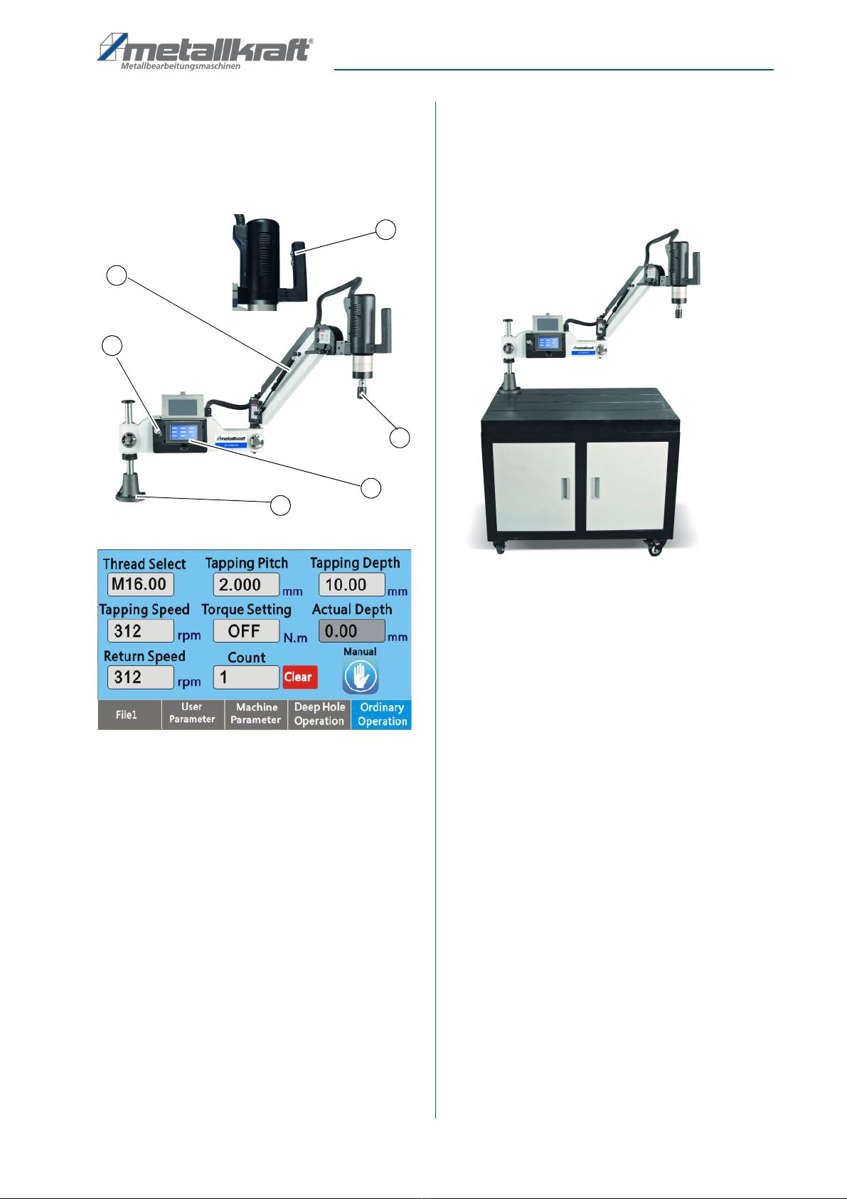
6 Description of device
6.1 Representation
Illustrations in these operating instructions are for
basic understanding and may differ from the actual
design.
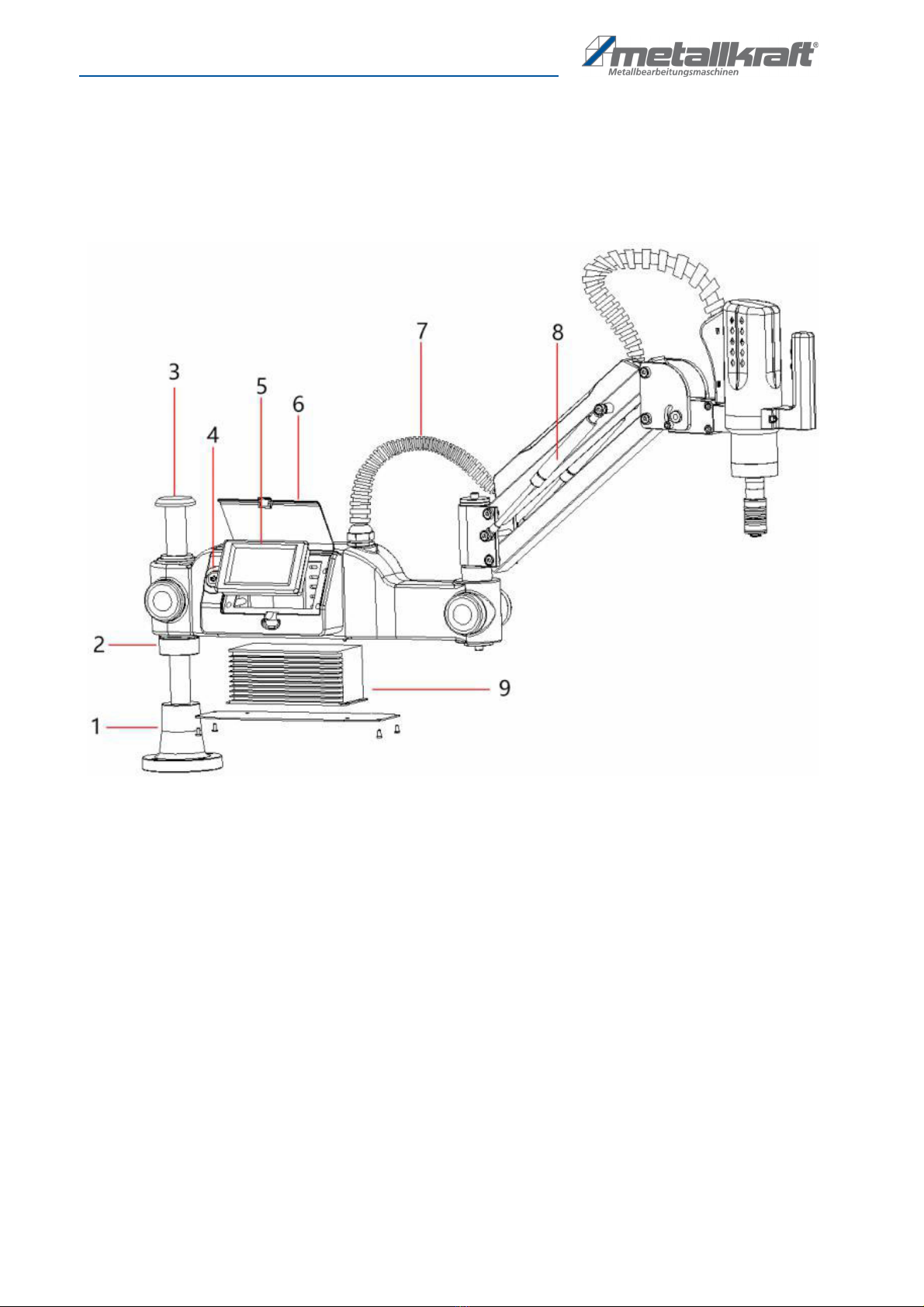
Fig. 3: Description of thread tapping achine GS 1100-16 E
1 Extension ar
2 Tap head
3 Control panel
4 Machine carrier
5 ON/OFF switch
6 Operation keys of the tap: forward run (tapping), re-
verse run (retraction of the tap)
Scope of delivery:
- Thread Tapping Machine
- Operating instruction
-
GS 1100-16 E
:
8 x Tapping chuck GT12 (M3, M4,
M5-6, M8, M10, M12, M14, M16)
-
GS 1200-24 E
:
9 x Tapping chuck GT24 (M6, M8,
M10, M12, M14, M16, M18, M20, M22-24)
-
GS 1200-36 E
:
13 x Tapping chuck GT24 (M6, M8,
M10, M12, M14, M16, M18, M20, M22-24, M27, M30,
M33, M36)
Accessories (not included)
4460005
Substructure
for threading achines
(Fig. 4)
900x600x875
4460010
Magnet foot
for GS 1000-12P & GS 1100-16E
4460011
Magnet foot
for GS 1200-24E & GS 1200-36E
Fig. 4: Accessories - substructure for threading achines
7 Assembly
Please check the parts carefully against the packing list.
Then asse ble the as described in the following steps.
Step 1: Carefully re ove the achine parts fro the
packaging.
Step 2: Select a suitable asse bly table that is flat and
stable and provides sufficient working space.
Suitable work tables can be ordered fro
METALLKRAFT as optional accessories.
Step 3: Mount the achine carrier. Align the achine
support with the screw holes on the worktable
and fit the four screws. If you have not purcha-
sed a METALLKRAFT worktable, you will have
to drill four ounting holes on the worktable itself
(see diagra „Mounting holes for the achine
carrier“, Fig. 5).
Step 4: Adjust the height li it ring.
Adjust the height according to the actual conditi-
ons and tighten the screws on the li iting ring.
Step 5: Guide the copper sleeve on the underside of the
achine of the achine into the optical axis of
the achine carrier so that the lower copper
sleeve copper sleeve is close to the li iting ring.
is located.
1
4
2
3
5
Gewinde-Auswahl Gewindetiefe
Geschwindigkeit Dreh o ent Ist-Wert Tiefe
Rücklauf-
geschwindigkeit
Gewindesteigung
Zähler
Benutzer-
para eter
Maschinen-
para eter
Tiefbohrloch-
Betrieb
Allge einer
Betrieb
Löschen
Control panel
6

10 GS-E Series | Version 1.09
Assembly
Step 6: Position the optical axis cover on the screw hole
at the top of the shaft, insert it correctly and tigh-
ten it.
Fig. 5: Asse bly
7.1 Setting the tapping direction
Fig. 6: Setting the tapping direction
The factory setting is vertical tapping ode. Before star-
ting tapping, ake sure that an exact right angle is set
between the worktable plane and the ain axis of the
tapping achine.
Step 1: Loosen the locking screws on both sides as
shown in figure 6A.
You can rotate the threading spindle down 90
degrees to switch to horizontal threading ode
or adjust the position of the spindle and work-
piece in vertical orientation.
You can rotate the threading spindle down 90
degrees to switch to horizontal threading ode,
or adjust the position of the spindle and work-
piece in vertical align ent and then tighten both
side screws. The horizontal tapping ode is
shown in Figure 6B.
Step 2: The spindle can be rotated 360 degrees to per-
for tapping operations at any angle, auto ati-
cally aintaining the horizontal position.
Step 3: To return to vertical tapping ode, loosen the
locking screws and adjust the vertical position of
the spindle. Then tighten the locking screws
again.
7.2 Electrical connection
Fig. 7: Electrical connection
1
2
3
4
A
B
360° Rotate
90° Rotate
Lock the
screws
A EN ION!
The unit ay only be operated with the supplied
ains cable! Plug the ains cable into the socket on
the back of the achine as shown in figure 7.
When doing so, ake sure that the achine is pro-
perly connected to the protective earth conductor to
avoid electrical accidents.
Operation
GS-E Series | Version 1.09 11
8 Operation
Before using the achine, please read this anual care-
fully and fully understand the design and function of the
achine.
If the cutting edge of the tap is worn, resharpen it or re-
place the tap. Otherwise, the achine ay be da aged
due to overloading.
8.1 Operation
Press the ON/OFF button to switch on the achine. The
display lights up.
Touch the display (touch screen) to access the user in-
terface.
There is a anual and an auto atic operating ode.
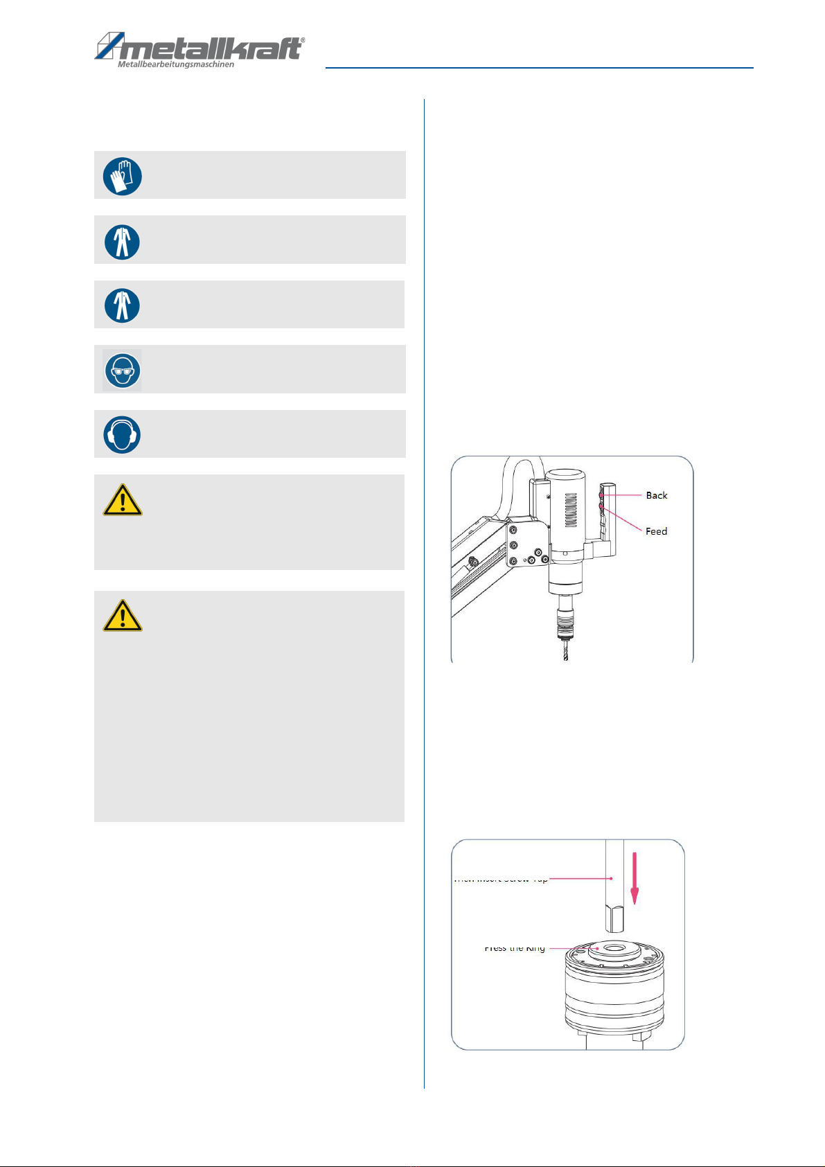
The operating ode can be changed with the "MANUAL"
field. As shown in figure 8, in anual operation ode,
press and hold the "Feed" button on the handle to per-
for the anual tapping operation and press the "Back"
button to retract.
To switch to auto atic operation ode, press the "MA-
NUAL" field on the display. After selecting the para e-
ters for the tapping process, press the "Feed" button to
perfor the auto atic tapping. The entire thread cutting
process then runs auto atically.
Fig. 8: Operation
Selection of the right screw tap
Take the tap chuck that atches the tap, press the ring
onto the tap as shown in Figure 9, then insert the square
shank of the tap to the end of the inner hole, loosen the
ring and insert the tap co pletely, in reverse order re-
ove the screw tap
.
Fig. 9: Selection of the right screw tap
Wear suitable protective gloves!
Wear protective clothes!
Wear protective work clothing
Use protective goggles!
Wear hearing protection!
A EN ION!
Never use a tool with larger di ensions than appro-
ved by the anufacturer (see specifications in the
technical data).
A EN ION!
- Before each cutting operation, ake sure that the
workpiece is not under pressure.
- Check that the tap is exactly centred on the core
hole.
- Only cut with sharp tools!
- Re ove chips regularly to avoid large a ounts of
chip residue. This could lead to da age to the tool.
- The tool and the cutting residues are very hot at the
end of the cutting process. Do not touch, risk of
burns!
Insert the
screw tap
Pressing
the ring

12 GS-E Series | Version 1.09
Operation
Quick-change thread tapping spindle
Insert the tapping chuck as shown in Figure 10, hold the
outer ring of the tapping shaft and push it upwards, insert
the tapping pliers upwards into the align ent slot and
push it to the end and release the outer ring.
By reversing the process, the tap collets can be quickly
re oved.
Fig. 10: Tapping spindle
8.2 Turn on/off
Press the on/off switch on the achine to switch the a-
chine on.
When you press the on/off switch to turn the unit off, it
takes a few seconds for the unit to turn off.
8.3 User interface
Fig. 11: User interface
hread Select:
Click the “Thread Select” to choose the
thread size, it will auto atically generate the thread pitch
and torque.
apping Pitch:
In the Thread Select interface,if you
choose the thread, it will generate the thread pitch auto-
atically, or you can set nonstandard pitch value.
Input range:
0.001-10 .
apping depth:
Setting of the desired thread depth.
Value range:
0.01-500 .
apping speed:
The setting of the cutting speed of the
threading achine.
Calculation: Vgs=V ax/L; if the ax. otor speed is
V ax=3000 rp and the gear ratio is L=16, the axi-
u speed of tapping is Vgs=V ax/L=3000/16=187
rp . .
Return speed:
Setting of the return speed of the thread
tapping achine.
orque setting:
To set this para eter, the torque pro-
tection function ust be opened on the user para eter
interface.
After setting the torque protection: During achining, if
the control detects that the tapping force reaches the
preset protection torque, the otor stops tapping, then
retracts to the preset nu ber of threads and then conti-
nues tapping until the preset thread depth is reached.
Note: Torque protection in nor al operation is available
in anual and auto atic operation odes, but not in
deep hole operation.
Counter:
Recording of the processed workpiece quan-
tity. The „Clear“ button resets the nu ber to zero.
Actual depth:
Actual value thread cutting depth in a-
nual and auto atic operating ode. The current thread
cutting depth is auto atically deleted each ti e the
thread cutting achine is started.
In the event of an interruption in auto atic thread cutting
ode, the thread cutting depth is not deleted! When the
thread-cutting achine is restarted, the re aining depth
continues to be cut up to the preset value.
Manual/Automatic mode:
select the desired ode by
touching the screen.
Manual mode:
On the user interface, select the thread, the thread cut-
ting depth, the torque, the thread cutting speed and the
reverse speed.
In the anual thread cutting process, press and hold the
forward button until you cut to the preset thread cutting
depth. The otor stops auto atically. Release the for-
ward button, press and hold the reverse button until the
tap leaves the workpiece.
Note: In anual operation ode, each ti e the forward
button is pressed, the current tapping depth is deleted.
Hold the outer ring
and push it upwards
Insert the tap collet
upwards
Gewinde-Auswahl Bohrung-Abstand Gewindetiefe
Geschwindigkeit Dreh o ent Ist-Wert Tiefe
Rücklauf-
geschwindigkeit
Gewindesteigung
Zähler
Benutzer-
para eter
Maschinen-
para eter
Tiefbohrloch-
Betrieb
Löschen
Allge einer
Betrieb

Operation
GS-E Series | Version 1.09 13
Automatic mode:
On the user interface, select the thread, thread cutting
depth, torque, thread cutting speed, reverse speed and
delay ti e.
In the auto atic thread cutting process, press the for-
ward button, the thread cutting achine auto atically
cuts to the preset thread depth. Now that the delay ti e
has elapsed, the tapping achine auto atically exits the
workpiece at the set return speed.
Note that there is
another return run as standard when exiting!
8.4 Language settings
Step 1: Switch on the device using the on / off switch
Step 2: Select "Machine para eters" (Fig.12) in the
enu bar.
Step 3: Enter the password (112233) and confir .
Step 4: Select the enu ite English / Chinese and keep
pressing until the desired language appears.
Fig. 12: Overview enu
8.5 Deep hole operation
Fig. 13: Use interface
The display such as
thread selection
,
tapping pitch,
tapping depth, speed, return speed
and
actual value
depth
- functionally identical to nor al operation.
apping circles:
each tapping depth during deep hole
operation
If 5 circles are set with a thread pitch of 0.5 , the
depth of each threading process is 2.5 .
Return depth:
Return cycles during deep hole opera-
tion. If 5 gears are set with a thread pitch of 0.5 , the
depth of each return is 2.5 .
NOTE:
The value for the return depth should be s aller
than the value.
Manual/Automatic mode:
select the desired operating
ode by touching the screen.
Functioning as in nor al ode.
8.6 Storage and recall of workpiece
parameters
Fig. 14: User interface
Select a workpiece and set the achining para eters.
These are auto atically saved and the workpiece is a-
chined with the last saved para eters the next ti e the
workpiece is called up.
A total of 10 groups of workpiece achining para eters
can be can be stored.
8.7 User parameter
Fig. 15: User interface
Hole bottom delay:
the ti e stay at the botto after re-
ach preset depth and before retreat fro the hole,range
is 0-10 seconds.
Motor direction:
Click the button to select the otor
rotation direction (left or right rotation).
Gewinde-Auswahl Bohrung-Abstand Gewindetiefe
Geschwindigkeit Schneid-Zyklen Ist-Wert Tiefe
Rücklauf-
geschwindigkeit
Gewindesteigung
Rücklauf-Tiefe
Benutzer-
Para eter
Maschinen-
Para eter
Tiefbohrloch-
Betrieb
Löschen
Allge einer
Betrieb
Motor-Typ
Servo-
Initialisierung
Benutzer-
para eter Zurück
Bohrungsboden-
Verzögerung Zyklen Motor-Drehrichtung
Rückwärts-
Zyklen
Benutzer Parameter
Auto atischer
Rücklauf
OFF
Dreh o ent
Schutz
OFF Zurück
Rechts
Initialisierung
Zyklus-Intervall
Eingabe

14 GS-E Series | Version 1.09
Cleaning, maintenance and repair
Retract cycles:
To ensure that the tap can successfully
retract fro the workpieces after tapping, the cycle value
for retraction should be greater than that for tapping.
Value range:
0-10
8.8 User parameter for lubricating and
scrap blowing
Abb. 16: User interface
Oil Valve:
touch the button to turn on the Lubrication
switch,will spay tapping oil auto atically when threa-
ding,press again to turn off the function.
Delay time:
to set oil spraying ti e, ti e between 0.1-25
seconds adjust ent.
Air valve:
Press the button to turn on the Scrap Blowing
switch, blowing scrap auto atically when reverse, will
stop auto atically after finish.
8.9 Adjusting the coupling torque of
the collet chuck
If the collet clutch has slipped during nor al tapping ope-
ration but the tap torque is not exceeded, or if it slips du-
ring tapping, the torque lock value is too s all. Set the
torque of the tap clutch higher.
If the tap's torque is exceeded during nor al operation of
the tap but the collet's clutch does not slip, this is an indi-
cation that the torque protection value is too large and
the clutch's torque ust be set s aller.
Adjustment steps:
Re ove the locking ring
Fir ly hold the tapping sleeve in place
Adjust the torque with the torque spanner (see fig. 17)
Align the slot on the top with the hole in the outer rin
Insert the retaining ring end into the hole below the
slot, let it snap into place.
Fig. 17: Adjusting the coupling torque of the collet chuck
9 Cleaning, maintenance and re
pair
9.1 Cleaning and maintenance
ips and recommendations
To ensure that the threading achine is always in
good operating condition, regular care and ain-
tenance work ust be carried out.
WARNING!
Danger in case of insufficient quali-
fication of persons!
Insufficiently qualified persons cannot assess the
risks involved in repair work on the threading
achine and expose the selves and others to the
risk of serious injury.
- All aintenance work ust be carried out by quali-
fied personnel only.
NO E!
Oil, grease and cleaning agents are hazardous to the
environ ent and ust not be disposed of in waste-
water or nor al household waste. Dispose of these
agents in an environ entally friendly anner.
Cleaning rags soaked in oil, grease or cleaning
agents are highly fla able. Collect the cleaning
rags or the cleaning wool in a suitable, closed contai-
ner and dispose of the in an environ entally fri-
endly anner - not: put the in the household waste!
Wear suitable protective gloves!
Wear protective clothes!
Wear protective goggles!
Dreh o ent
verringern
Dreh o ent
erhöhen
Siche-
rungsring
Bohrung

Disposal, recycling of old equipment
GS-E Series | Version 1.09 15
Clean the achine after each use.
Do not re ove etal or residual pieces with bare hands,
but use safety gloves to avoid cuts.
Clean all painted surfaces with a soft, da p cloth.
Never use solvents to clean plastic parts or painted sur-
faces. This ay cause the surface to loosen and result in
consequential da age.
9.2 Overhaul of the fuse
If you press the on/off switch of the achine and the a-
chine does not start, check the ains cable, the on/off
switch and check the fuse.
As shown in the illustration, pull out the fuse in the socket
to check. If the fuse is blown or defective, it ust be re-
placed with a new fuse of the sa e type.
Fig. 18: Fuse
9.3 Repair
As a result of wear and tear, it ay be the case that
aintenance work ust be carried out on the achine .
For aintenance work, please contact your nearest
Metallkraft dealer. Please write down the following infor-
ation fro the achine or fro the operating instructi-
ons beforehand, so that you can be helped with your
proble in the best possible way:
- Model of the achine,
- Serial nu ber of the achine,
- Exact error description.
10 Disposal, recycling of old
equipment
In the interest of the environ ent, care ust be taken to
ensure that all co ponents of the tapping achine are dis-
posed of only via the designated and approved channels.
10.1 Decommission
Discarded devices ust be taken out of service i ediately
in a professional anner in order to avoid later isuse and
the endanger ent of the environ ent or persons.
- Dispose of all environ entally hazardous operating
aterials fro the old device.
- Disconnect the power cable.
- If necessary, disasse ble the tapping achine into a-
nageable and recyclable asse blies and co ponents.
- Dispose of the achine co ponents and operating
aterials in the designated disposal channels.
10.2
Disposal of electrical equipment
Electrical equip ent contains a large nu ber of recycla-
ble aterials as well as co ponents that are har ful to
the environ ent. These co ponents ust be disposed
of separately and properly. If in doubt, contact the uni-
cipal waste disposal service. If necessary, enlist the help
of a specialized disposal co pany for reprocessing.
10.3 Disposal via municipal collection
points
Disposal of used electrical and electronic equip ent (to
be applied in the countries of the European Union and
other European countries with a separate collection sy-
ste for this equip ent).
The sy bol on the product or its packaging
indicates that this product should not be trea-
ted as nor al household waste, but should
be taken to a collection point for the recycling
of electrical and electronic equip ent.
By helping to dispose of this product correctly, you are
protecting the environ ent and the health of those
around you. The environ ent and health are endange-
red by incorrect disposal. Material recycling helps to re-
duce the consu ption of raw aterials. For ore infor-
ation about recycling this product, contact your local
council, unicipal waste disposal service or the shop
where you purchased the product.
10.4 Disposal of lubricants
The anufacturer of the lubricant akes the disposal in-
structions for the used lubricants available. If applicable,
ask for the product-specific data sheets.
DANGER!
Repairs or aintenance work ay only be carried
out by qualified and trained personnel.

16 GS-E Series | Version 1.09
roubleshooting
11 Troubleshooting
Fault code Possible cause Solutions
Erry-001 Drive odule alfunction Check,
- the vertical position of the ain shaft,
- whether the gearbox is blocked,
- whether the screw tap is ja ed in the work-
piece,
- whether the drive and the otor are da aged,
- whether the connection of the ains cable is
correct.
Erry-006 Engine blocked Check,
- the Motor,
- whether the gearbox is blocked.
Erry-008, 091, 092, 093 Motor encoder fault Check that the CN5 encoder cable is properly
connected
Erry-04, Erry-010 Drive overload Check,
- whether the screw tap chip re oval is working.
- whether the workpiece is stainless steel and
other hard aterials, if so, use a larger tapping
achine.
Erry-200 Drive: Internal co unication error Encoder signal has interference, find the source of
interference and keep it far away.
Erry-312 Torque protection error Turn off the torque protection or set the torque pro-
tection value to a larger value in User Para eter in-
terface.
Spare parts
GS-E Series | Version 1.09 17
12 Spare parts
12.1 Ordering spare parts
The spare parts can be obtained fro the authorized de-
aler.
Specify the following key data when aking inquiries or
ordering spare parts:
- Device type
- Ite nu ber
- Ite nu ber
- Year of anufacture
- Quantity
- desired shipping ethod ( ail, freight, sea, air,
express)
- Shipping address
Spare parts orders without the above infor ation cannot
be considered. In the absence of infor ation on the ship-
ping ethod, shipping will be at the discretion of the sup-
plier.
Infor ation on the device type, article nu ber and year
of anufacture can be found on the type plate, which is
attached to the device.
Example
The control panel for the GS 1000-12 P thread tapping
achinee ust be ordered. The control panel has the
ite nu ber 5 in the spare parts drawing 1.When orde-
ring spare parts, send a copy of the spare parts drawing
with the arked co ponent (control panel) and arked
ite nu ber (5) to the authorized dealer and provide the
following infor ation:
Type of device:
hread apping Machine
GS 1100-16 E
Ite nu ber:
4450116
Spare part drawing:
1
Position nu ber:
5
he item number of your machine:
Thread Tapping Machine
GS 1100-16 E 4450116
GS 1200-24 E 4450124
GS 1200-36 E 4450136
DANGER!
Risk of injury due to the use of
of incorrect spare parts!
The use of incorrect or faulty spare parts can result in
danger to the operator and cause da age and al-
functions.
- Only original spare parts fro the anufacturer or
spare parts approved by the anufacturer are to be
used.
- In case of any uncertainties, always contact the a-
nufacturer.
ips and recommendations
Use of non-approved spare parts will void the anu-
facturer's warranty.
18 GS-E Series | Version 1.09
Spare parts
12.2 Spare parts drawing
The following drawings should help you to identify necessary spare parts in case of service.
Spare parts drawing 1
Fig. 19: Spare parts drawing 1
1 Machine carrier
2 Stop ring
3 Optical axis cover
4 On/Off switch
5 Control panel
6 Control panel protective cover
7 Cable duct
8 Air spring
9 Controller
Spare parts
GS-E Series | Version 1.09 19
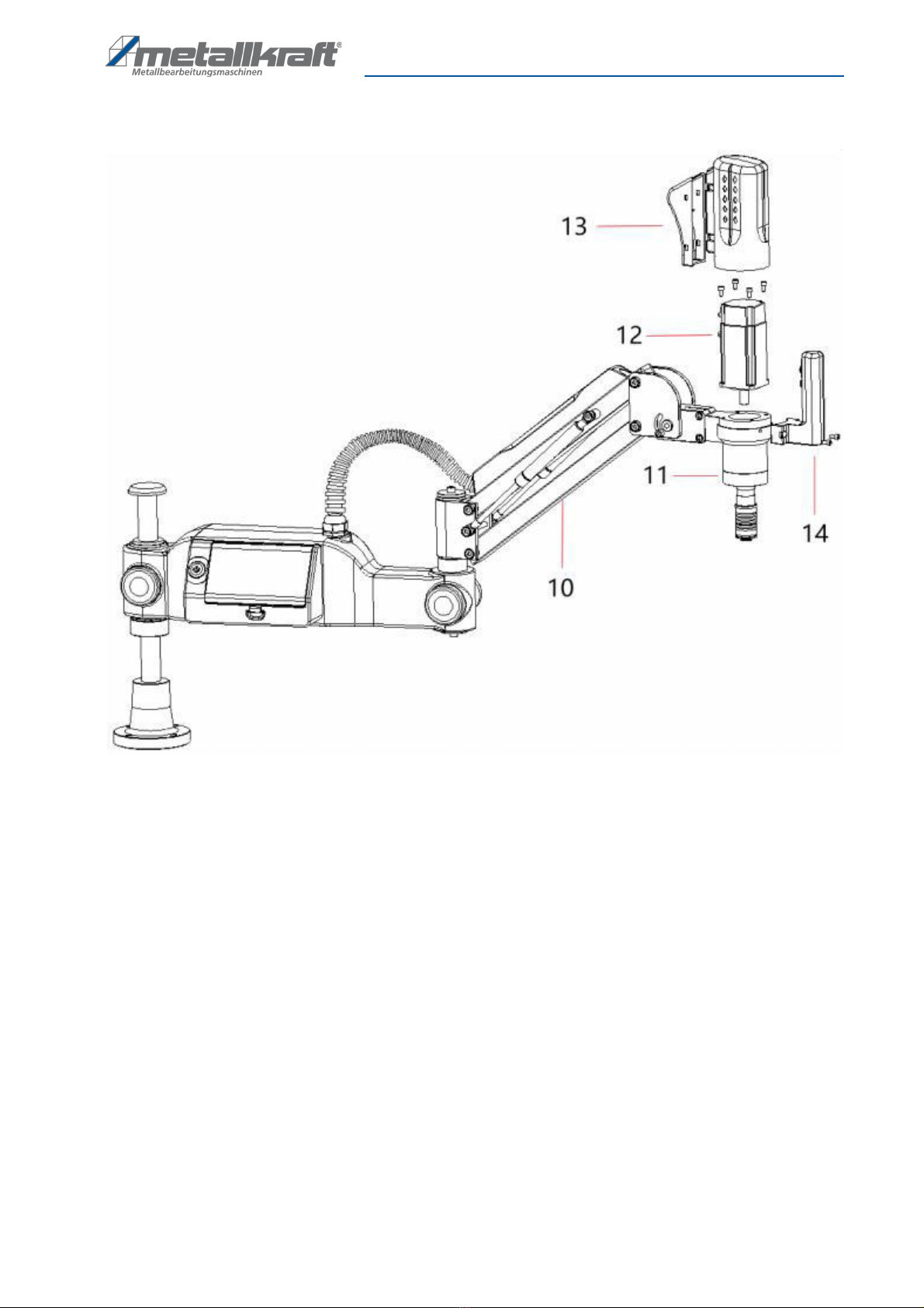
Spare parts drawing 2
Fig. 20: Spare parts drawing 2
10 Upper fra e
11 Reducer
12 Servo otor
13 Motor cover
14 Control lever

20 GS-E Series | Version 1.09
Wiring Diagram Control Unit
13 Wiring Diagram Control Unit
Fig. 21: Wiring Diagra Control Unit
FOR
Motor possitive trans ission
REV
Motor reversal
Out1
Set output standby 1, function according to custo er requir ents
24V
Power supply 24V/250 A
GND1
Power 0V
In3
Input standby 1, set the function according to custo er require ents
Out 2
Set output standy 2, function according to custo er require ents
Out 3
Set output standby 3, function according to custo er require ents
CN1 terminal: L,N as 220VAC power input.
CN2 terminal: Power line of servo otor. (note the direction of
the plug)
CN3 terminal: Handle control direction line, FOR ter inal is
connect for start and forward direction,REV ter i-
nal is for reverse direction,and the GND1 is
connected to the COM (for the public ground).
CN4 terminal: LCD touch screen control line.
CN5 terminal: Encoder line of servo otor.
This manual suits for next models
5
Table of contents
Other Metallkraft Industrial Equipment manuals


Popular Industrial Equipment manuals by other brands


-Series operating instructions")


Zehnder Rittling
Zehnder Rittling ComfoClime 24 Installer manual

Siemens
Siemens Simatic Net Scalance M812 operating instructions

Festo
Festo HGPM-xxx-G series operating instructions

ABB
ABB OVR-15 Operator's Quick Reference Guide

CMC
CMC OilQSens OQ 3000 user manual

Schaeffler
Schaeffler SES Series Mounting manual