when the product is operated in the intended operational electromagnetic
environment.
This product is intended for use in industrial locations. However, harmful
interference may occur in some installations, when the product is connected to a
peripheral device or test object, or if the product is used in residential or
commercial areas. To minimize interference with radio and television reception and
prevent unacceptable performance degradation, install and use this product in strict
accordance with the instructions in the product documentation.
Furthermore, any changes or modifications to the product not expressly approved
by National Instruments could void your authority to operate it under your local
regulatory rules.
Special Conditions for Marine Applications
Some products are approved for marine (shipboard) applications. To verify marine
approval certification for a product, visit ni.com/product-certifications, search by
model number, and click the appropriate link.
Notice In order to meet the EMC requirements for marine applications,
install the product in a shielded enclosure with shielded and/or filtered
power and input/output ports. In addition, take precautions when
designing, selecting, and installing measurement probes and cables to
ensure that the desired EMC performance is attained.
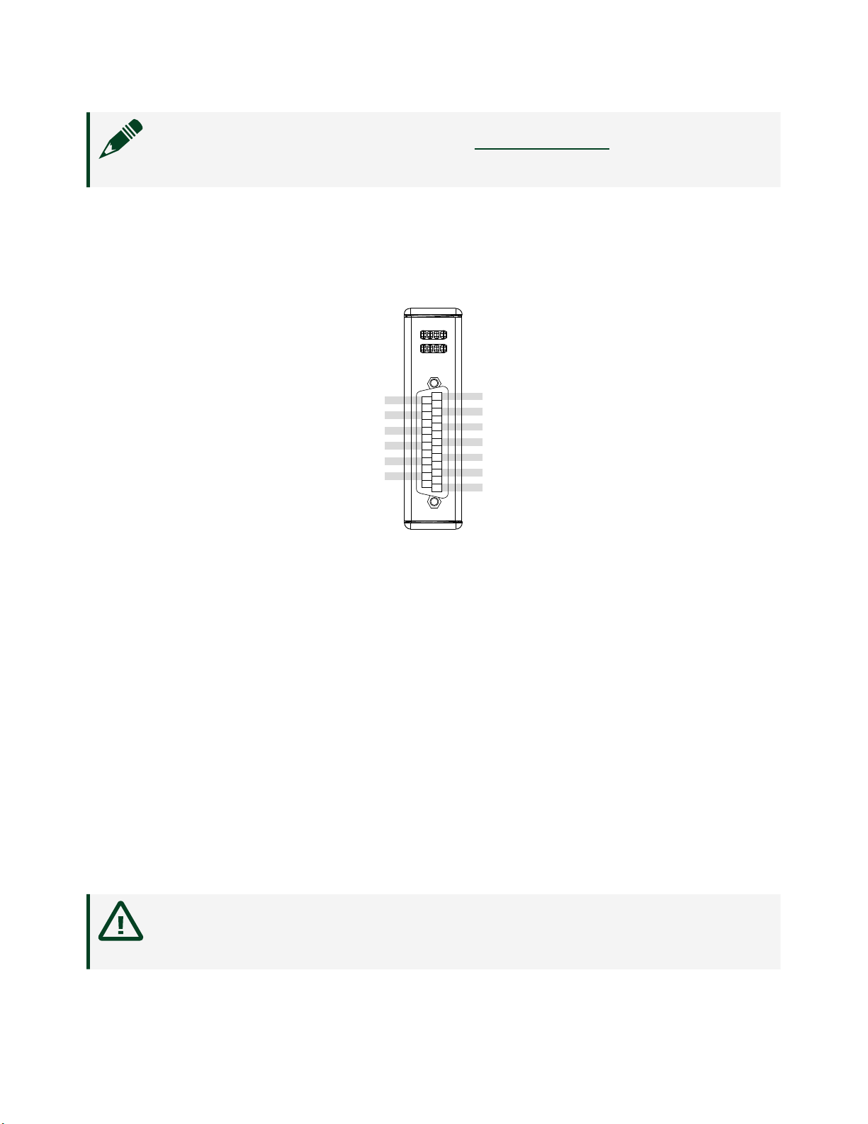
Preparing the Environment
Ensure that the environment in which you are using the NI-9475 meets the following
specifications.
Operating temperature (IEC 60068-2-1, IEC 60068-2-2) -40 °C to 70 °C
Operating humidity (IEC 60068-2-78) 10% RH to 90% RH, noncondensing
Pollution Degree 2
Maximum altitude 2,000 m
Indoor use only.
ni.com
6
NI-9475 Getting Started