Nipponia E-viball User manual

Owner's Manual
Nipponia S.A.
EN

2
Thank you for purchasing the E-VIBALL scooter. This model is designed for safety, built for durability and
perfected for daily
street use.
The superior vehicle design and built-in technology will meet your expectations for an economical and eco-friendly lifestyle.
This Owner’s manual contains basic instructions on how to operate, inspect and maintain your scooter. Please read it carefully
and thoroughly. Correctly operating, maintaining and repairing your scooter will minimize any possible risks and result in its
best performance.
The authorized Nipponia service points will be glad to provide you with more detailed instructions.
INTRODUCTION EN

IMPORTANT MANUAL INFORMATION EN
3
Important information contained in this manual is marked using the following symbols:
Important information or instructions. Failure to follow these instructions may result in heavy damage to
your scooter, serious injury or even death.
Important information or instructions. Failure to follow these instructions may result in damage to your
scooter or minor injury.
Note: Product and specifications are subject to change without prior notice.
CAUTION
! WARNING
CAUTION
•This manual is an integral part of the scooter and must always accompany it, even in the event of a resale.
•If you have any questions concerning the contents of this manual or need further information regarding the operation of
your scooter, do not hesitate to contact your local Nipponia dealer.
•This booklet is compiled with the latest available information. However, due to constant improvements, modifications or
alterations may be made without prior notification. Updated versions can be downloaded from the Nipponia website
www.nipponia.com

IMPORTANT MANUAL INFORMATION EN
4
Dealer label (stamp) here

5
INTRODUCTION……………………..........
2
OPERATION AND DRIVING
INSTRUCTIONS........................................
26
WARRANTY INFORMATION.................
50
IMPORTANT MANUAL
INFORMATION........................................
3
Battery.......................................................
26
MAINTENANCE SCHEDULE.................
51
TABLE OF CONTENTS...........................
5
Battery storage………...............................
31
SERVICE PLAN......................................
52
SAFETY INFORMATION.........................
6
Pre-operation check list.............................
33
WIRING DIAGRAM.................................
54
DESCRIPTION OF THE VEHICLE........
10
Activating the motor…….............................
34
SPACE FOR NOTES..............................
52
Side view (left and right) ..........................
10
Braking...........................................................
35
Controls and instruments..........................
12
Parking.........................................................
36
MAIN COMPONENTS.................................
13
PERIODIC MAINTENANCE AND
MINOR REPAIR........................................
38
Smart key………………………………...…
Main switch / steering lock.........................
13
14
Tyres.........................................................
38
Dashboard unit...........................................
15
Tyre wear condition...................................
39
Handlebar switches –left...........................
17
Rim and Tyre information..........................
40
Handlebar switches –right........................
18
Rims..........................................................
40
Front brake lever.......................................
19
Brakes…………….....................................
41
Rear brake lever.......................................
19
Brake pads…............................................
41
Emergency key.........................................
20
Brake fluid.…............................................
42
Power switch……………….......................
21
Lubricating the levers................................
44
Charger and charging socket…................
21
TROUBLESHOOTING..............................
45
Smart APP…………………………………
Luggage box…….….................................
22
23
CLEAN AND STORAGE..........................
46
Glove compartment………………………..
24
Cleaning the vehicle..................................
46
Side stand....…….….................................
22
Storage......................................................
48
USB port......…….….................................
25
SPECIFICATIONS....................................
49
TABLE OF CONTENTS
EN

SAFETY INFORMATION EN
6
Safe riding
1. Always perform the pre-operation inspection before driving.
2. The scooter should not be used by anyone who does not hold a valid driving license.
3. Many accidents involve motorcycles not seen by other drivers, so please pay attention to the following:
•Wear brightly-coloured clothes.
•Do not drive too close to other vehicles or in another driver’s blind spot.
•Avoid overtaking.
4. Always follow local traffic regulations.
•Driving above the speed limit is the reason for many accidents. Driving speed must not exceed the limit specified by traffic
regulations and allowed by road conditions.
•Always signal when turning or changing lanes in order to attract the attention of the other drivers.
5. Never drive under the influence of alcohol or other drugs; it dramatically increases the risk of accidents.
6. Exercise special attention when driving over crossroads or parking area exits.
7. When driving you must hold the handlebars with both hands and place your feet on the footboard. The passenger should hold the
handgrips or the driver and place his feet on the footrests.
8. This scooter is designed for on-road use only. It is not suitable for off-road use.
Protective clothing
1. For your safety, the driver and passenger should both wear helmets. Use of additional safety apparel (gloves, glasses, protective
wear) is recommended.
2. Do not wear loose clothing, as it may be caught by the handle levers, the kick starter or the wheels and could lead to an accident.

SAFETY INFORMATION EN
7
Vehicle modifications
Making any modifications to the scooter or replacing the original components can affect its performance and safety and/or render it
illegal for use. Observe applicable laws and all national and local regulations concerning vehicle equipment. Additionally, such
modifications will cancel the warranty.
Loading
Adding accessories or cargo to your scooter can adversely affect stability and handling if the weight distribution of the scooter is
changed. Use extra care when riding a scooter with extra load. Here are some general guidelines to follow when loading cargo or
adding accessories to your scooter:
1. All accessories must be fastened securely on the vehicle in order to minimize vibration that could cause instability.
2. Any extra load should be placed as close to the gravity centre as possible and must be equally distributed on both sides of the scooter
to avoid imbalance and instability.
3. The tyre pressure must be adapted to the weight of the load and road conditions.
4. Make sure that any extra load is securely attached to the vehicle to prevent it from falling and being lost.
5. Do not hang any load on the handlebars or the suspension.
6. The total weight of the driver, passenger, accessories and cargo must not exceed the maximum load limit of the scooter (160kg).
Maximum load: 160 kg
(Total weight of rider, passenger,
cargo and accessories)
Total weight of rider, passenger, cargo and accessories

SAFETY INFORMATION EN
8
Accessories
When installing accessories not approved by Nipponia, attention should be paid to the following points:
1. The installation of the accessories must not affect the suspension travel, the light position and the steering angle.
2. Avoid installing any accessories that could hinder your access to vehicle controls and movement of your hands and feet as it could
impair your reaction in an emergency event.
3. Do not install a bulb with higher power than that specified. It could burn the fuse or cause problems to the electrical system due to
low voltage.
4. Do not add a sidecar to the scooter.
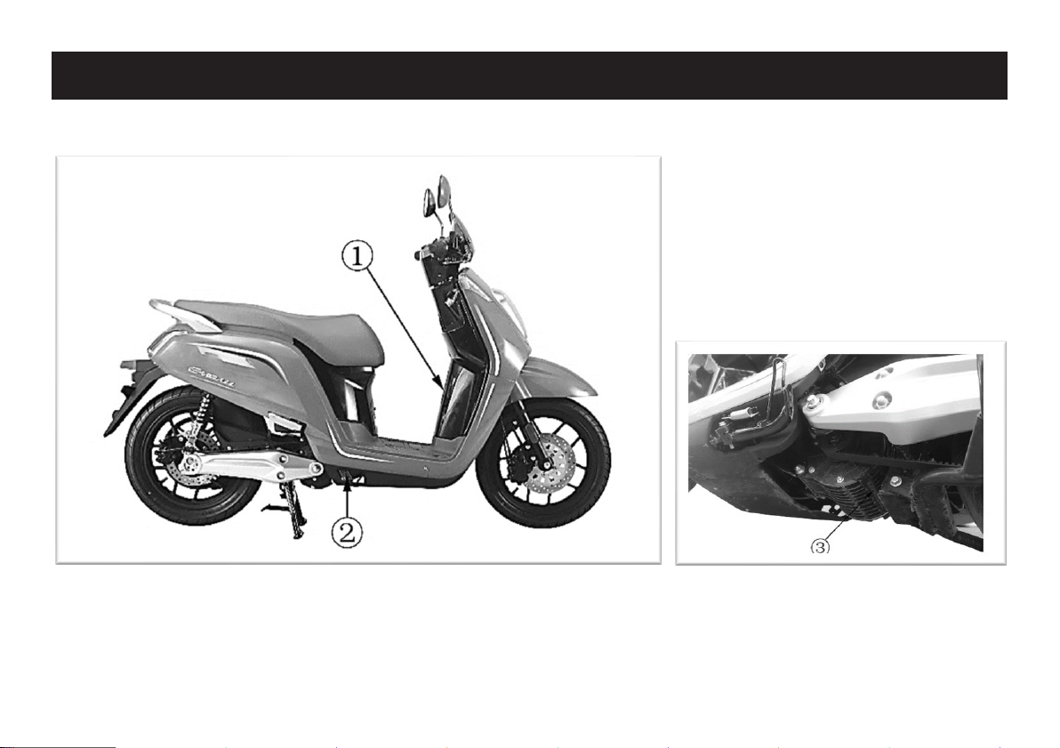
SAFETY INFORMATION EN
9
Serial number
1. VIN
2. Frame plate
3. Motor number
DESCRIPTION OF THE VEHICLE EN
10
Left side view
1. Side stand
2. Main stand
3. Left pillion step
4. Rear grip

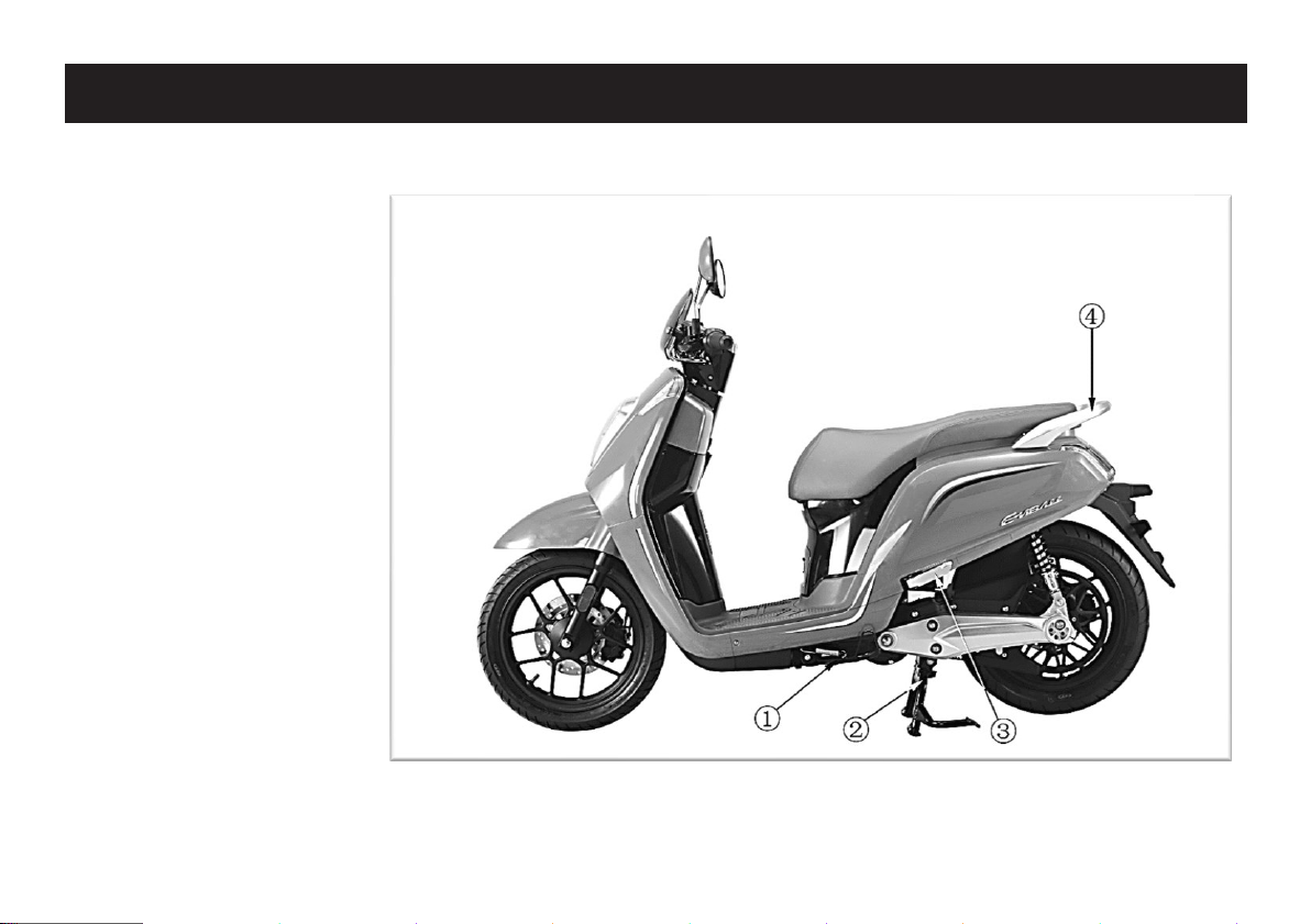
DESCRIPTION OF THE VEHICLE EN
11
Right side view
1. Charging port
2. Right pillion step
3. Luggage box

DESCRIPTION OF THE VEHICLE EN
12
Controls and instruments
1. Ignition switch
2. Start / Gear button
3. Throttle grip
4. Front brake lever
5. Hazard lights switch
6. Dashboard unit
7. Overtaking switch
8. Rear brake lever
9. High / Low beam switch
10. Turning switch
11. Horn / Cruise control button
MAIN COMPONENTS EN
EN
13
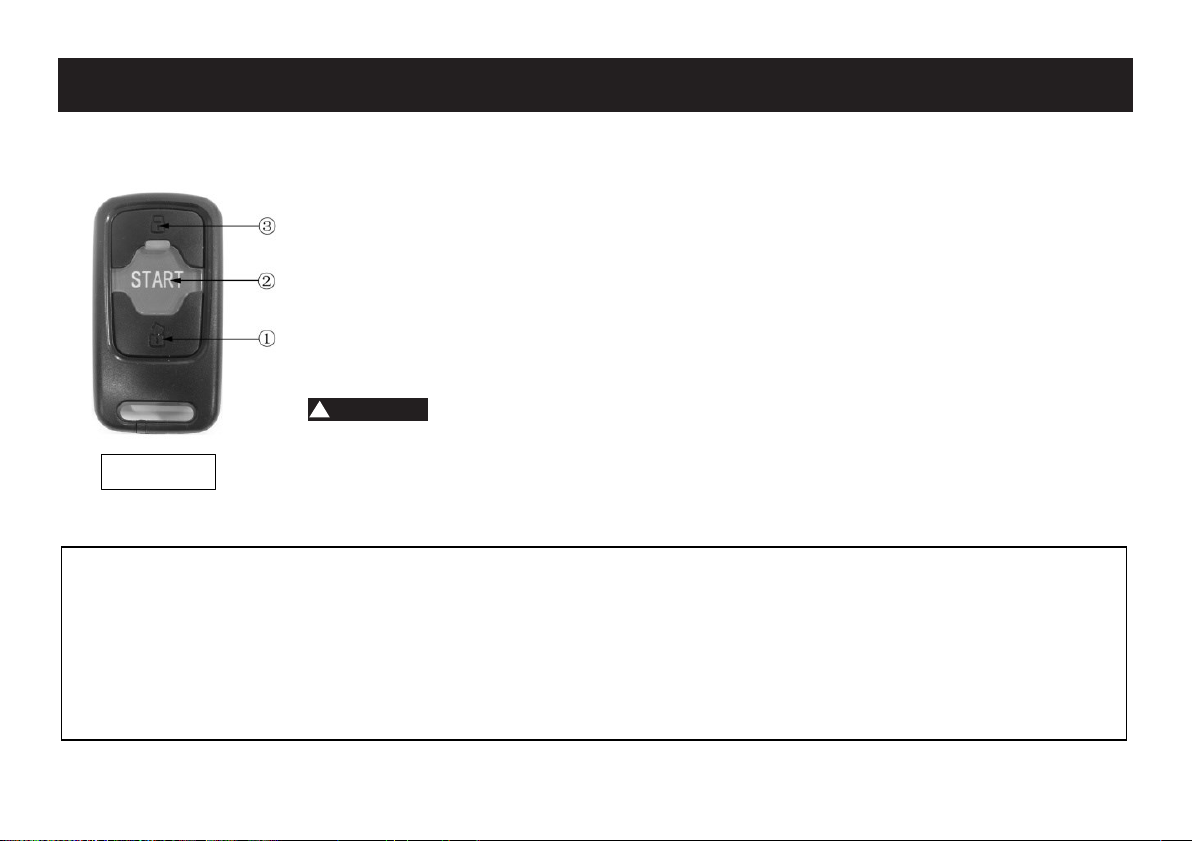
SMART KEY
This motorcycle is equipped with a keyless system. You can lock/unlock remotely your vehicle without using a key.
1. “Unlock”: Press this button to unlock the system. A blue light on the ignition switch and the rear
light will flash for 5 seconds, meaning that the motor can be activated. After 5 seconds, if you
do not turn the switch, the vehicle will be locked again.
2. “START”: Press this button to locate your vehicle. The blue light of the switch and the rear light
will flash 8 times. Also, the alarm will beep once.
3. “Lock”: Press this button to lock the vehicle. Then the alarm system will be immediately
activated.
The smart key can be effectively operated up to 1.5 meter. The frequency range can reach the 20m in
an open space. The physical makeup of the surrounding environment (hills, trees, buildings, etc.) may
affect the maximum frequency range.
! WARNING
Caution:
▪If the smart key is soaked with fuel, grease or liquid please wipe it off immediately to avoid any damage.
▪Do not dismantle the smart key, except for the battery replacement.
▪If you lose the smart key, contact your local dealer for key replacement.
▪Do not store mobile phone and other radio emitting devices in glove/storage compartments; radio frequency from this device may
interfere with the smart key system.
▪If the smart key is within the frequency range of the motorcycle, anyone can unlock the ignition switch to start the engine. To secure
your motorcycle when you park, turn off the power switch.
Smart key
MAIN COMPONENTS EN
EN
14
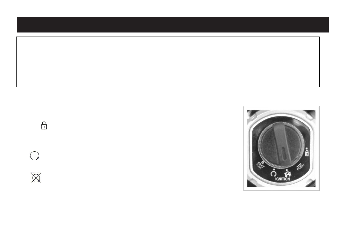
MAIN SWITCH / STEERING LOCK
The main switch/steering lock controls the ignition and lighting systems. It is also used to
lock the steering wheel. The main switch can be turned to the following positions:
LOCKED
Turn the main switch to “LOCKED” position. The steering is locked and cannot be turned,
the motor and the electrical system are off.
ON
All electrical circuits are supplied with power and the motor is active.
OFF
The motor and the electrical system are off
SEAT
Turn the main switch to “SEAT” position and press it to open the seat. The motor and the electrical system are off.
Notice:
▪Smart key is an electrical device. It may not work normally if the electrical circuit is damaged.
▪Do not let the smart key falling to the ground or put any load on it.
▪Keep the smart key away from direct sunlight, high temperature or humidity.
▪Do not scratch or puncture it.
▪Do not store it with magnetized parts.
▪Keep the smart key away from electrical device such as TV, Radio, Computer or Low frequency devices.
▪When washing the motorcycle, keep the smart key away.

MAIN COMPONENTS EN
EN
15
Never turn the main switch to OFF or LOCK position, while the vehicle is moving,
otherwise the electrical system will be switched off, which may
result in loss of control or an
accident. Make sure that the vehicle is stopped before turning the main switch.
DASHBOARD UNIT
Left turn signal indicator (1)
The left turn signal indicator flashes whenever the turn signal
switch is pushed to the left side.
High beam indicator (2)
Indicates that the high beam switch is in ON position.
Speedometer / Trouble code (3)
The speedometer shows the riding speed or the trouble code when
there is an engine problem.
READY indicator (4)
After pressing the start button and the motor is active, this indicator
is on. The “READY” indication remains on during driving.
P-gear indicator (5)
This indicator is on when the side stand is on the ground.
Right turn signal indicator (6)
The right turn signal indicator flashes whenever the turn signal
switch is pushed to the right side.
Bluetooth indicator (7)
This indicator is on when your mobile phone connects to the smart
APP via Bluetooth function.
Battery 2 level gauge (8)
The battery level gauge indicates the power remaining, on the left
! WARNING

MAIN COMPONENTS EN
EN
16
battery pack, before re-charging is required. When the last dash flashes, the power remaining is less than 15%.
Mobile network signal strength (9)
When the network signal is strong, the indicator is always on. It flashes when the signal is weak.
GPRS signal strength (10)
When the GPRS signal is strong, the indicator is always on. It flashes when the signal is weak.
Environment temperature indicator (11)
It displays the environment temperature.
System failure (12)
This indicator is on when the power system failure affects driving.
Power system overheat (13)
This indicator is on when the power system temperature affects driving.
Cruise control indicator (14)
This indicator is on when the scooter is in constant speed cruise mode.
Odometer (15)
The odometer shows the total distance traveled and the trip distance is reset every time the main switch is turned off.
Gear indicator (16)
Displays the current power train drive gear.
Clock (17) - Displays the current time.
Battery 1 level gauge (18) - The battery level gauge indicates the power remaining, on the right battery pack, before re-charging is
required. When the last dash flashes, the power remaining is less than 15%.

MAIN COMPONENTS EN
EN
17
HANDLEBAR SWITCHES - LEFT
Overtaking switch (1)
Use this switch when you consider overtaking. While the switch is
pressed, high beam is on. When released, low beam is on. This switch
can be also used at night to increase visibility.
High/Low beam switch (2)
Set the switch to position for the high beam.
Set the switch to position to for the low beam.
Turn signal switch (3)
Push this switch to position to signal a left-hand turn or to position to
signal a right-hand turn. To turn-off the signal lights press the switch in the
central position.
Horn button (4)
Press this button to sound the horn.
Cruise control button (5)
This model is equipped with a cruise control system, designed to maintain a
constant cruising speed. Press the cruise control button to activate cruise
control functionality. It is available on all versions of L3e (75km/h) and L1e
(45km/h) categories. Whenever the front or rear brake is applied, the cruise
control function will be deactivated.
1. Overtaking switch, 2. High / Low beam switch
3. Turn signal switch, 4. Horn button,
5. Cruise control button

MAIN COMPONENTS EN
EN
18
•Do not activate the cruise control button in heavy traffic or in bad weather conditions.
•Do not activate the cruise control button when travelling uphill or downhill.
HANDLEBAR SWITCHES - RIGHT
Hazard lights switch (1)
Press this switch to turn on both signal lights.
Gear switch button (2)
Press this button to switch gear (not available on 25 km/h version)
Start button (3)
Press this button to activate the motor.
! WARNING
1. Hazard lights switch, 2. Gear switch button,
3. Start button

MAIN COMPONENTS EN
EN
19
FRONT BRAKE LEVER
The front brake lever is located on the right handlebar grip.
To apply the front
brake, pull this lever towards the grip.
REAR BRAKE LEVER
The rear brake lever is located on the left handlebar grip.
To apply the rear brake, pull this lever towards the grip.
Table of contents
Other Nipponia Motorcycle manuals


