Nisca PR-L151 User manual

HEAT ROLLER UNIT
(MODEL No. : PR5302)
Operation Guide

Section 1・・・ Introduction
Section 2・・・ Preparation
Section 3・・・ Installation
Section 4・・・ Replacing the ribbon
Section 5・・・ Setting ribbon type
Section 6・・・ Maintenance
Section 7・・・ Countermeasure for troubles
1
Thank you for your selecting Heat Roller Unit PR-L151 (Model No. PR5302).
Please read this instruction booklet all through before using the unit.
Section 1: Introduction
Several illustrations are used in this operation manual to ensure safe operation.
The following conventions are used to identify the result caused by the use or operations not
following such illustrations.
◇ Markings which needs to be observed with special attention.
: This indicates that there is a danger of death or serious injury.
: This indicates that there is possibility of injury or damage on
property .
: This indicates the topics which should be carefully followed for
correct operation of this unit. If used incorrectly, there is a
possibility of causing damages on this unit, connected
equipment, and soft wares, etc.
◇Illustrations used in this instruction manual
This indicates items which are prohibited, “Prohibition mark”.
Important
Danger
Caution

2
Feature of this equipment
This Heat Roller unit is optional unit for Card Printer PR-L151 (Model No.PR5350) for over
coating.
●Hard coat type operation mode
The printed surface of the card by the card printer can be protected for long period by
coating the printed face with reinforced film.
●Soft coat type operation mode
By using hologram film as a coating ribbon, the card with higher security can be made.
●Reference Type Operation Mode
It is possible to place a hologram mark at the specified position on the card
There are following two types of power source for this Heat Roller unit .
Check the rating plate attached to the rear cover and connect to the correct power
source.
(1) If your power supply is 100VAC - 120VAC and 50 or 60 Hz,
please use the equipment with this name plate.
(2) If your power supply is 200VAC - 240VAC and 50 or 60 Hz,
please use the equipment with this name plate.
Caution
3
Please use the card (print media) and coating ribbon specified by the dealer for this
Heat-rollerunit.
If card or ribbon other than specified are used, over coating may not be
done correctly and it may result in equipment trouble.
Especially, do not use a ribbon made of flammable material as it will
causeafire.
If you are not sure as to the type of the card and ribbon which you are
going to use, please check with your dealer.
Caution
4
Points to pay attention before using:
(1) Never disassemble the equipment
Do not remove the screws fixing the top cover
andrearcoveranddisassemblethecovers.
There is no user replaceable parts inside, and
there is a possibility of causing electric shock.
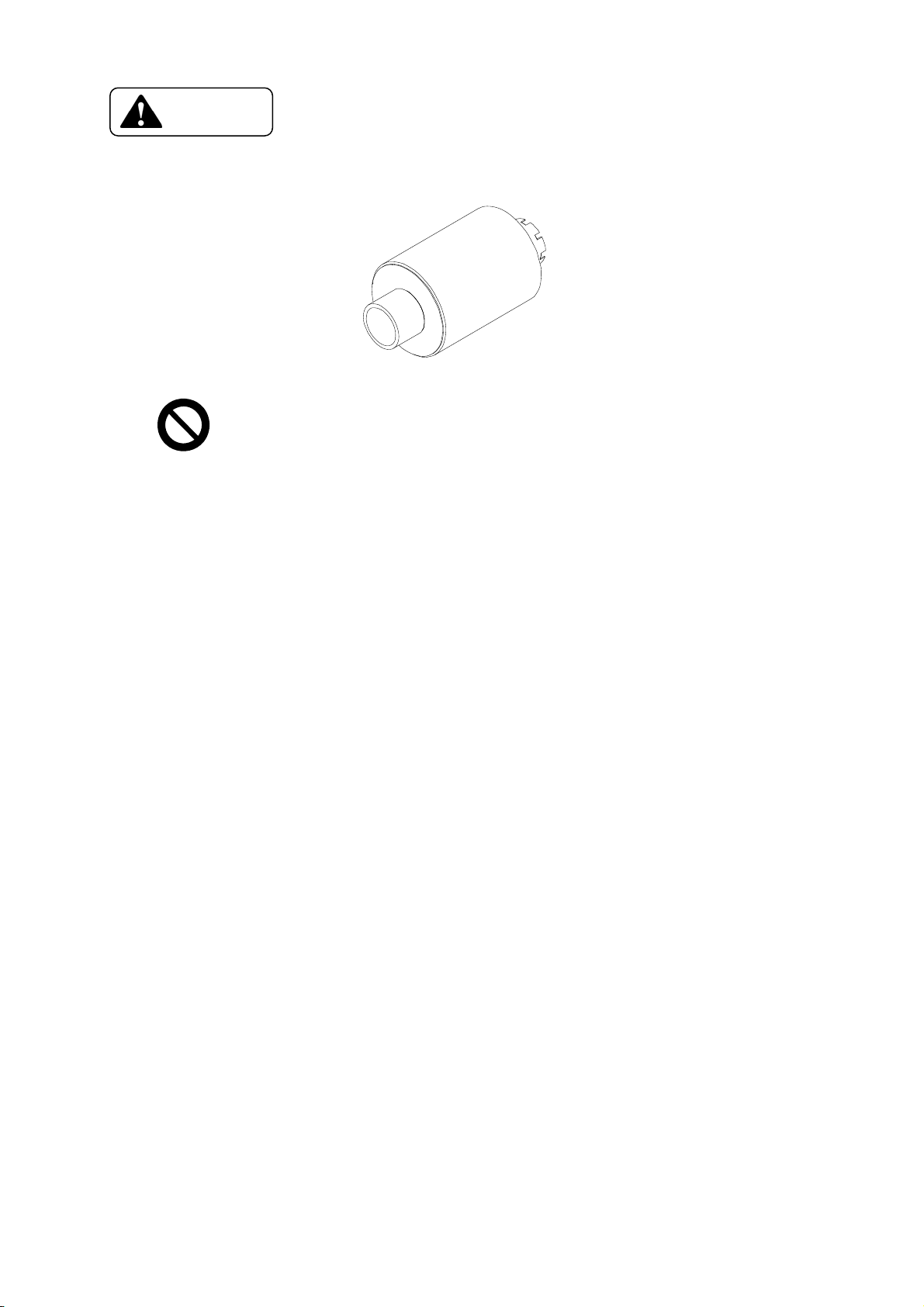
(2) Do not insert a flammable object or metal items in the ribbon room.
Thereisarollerwhichisashotasover150℃(302°F) inside
the ribbon room.
If a flammable object is inserted, it may cause a fire. Touching to
the lead wire of the heat roller may cause an electric shock.
Do not put finger or metal object inside.
Flammable items: Paper, wood piece, flammable
plastic, film, etc.
Metalobjects: Screwdriver,wire,paperclip,etc.
(3) Install the equipment correctly as described in page 11 of this booklet.
■Do not install at the place where it may cause a fire, such as following:
Near the heat radiating equipment such as stove etc.
Place where there is volatile fuel or filled with flammable gas.
Near the flammable items such as curtain, paper etc.
■Do not install at the place where the equipment may fall off.
On the unstable desk, inclined surface etc.
On unstable base which is not firmly constructed and may easily
be broken by earthquake etc.
This Heat Roller unit weighs 13Kg (28.7lbs).
It may cause an injury if it falls off and hit a person nearby.
■Do not install at the place with direct sunlight or with unusually high temperature.
The inside temperature of the equipment will increase and may
causeafire.
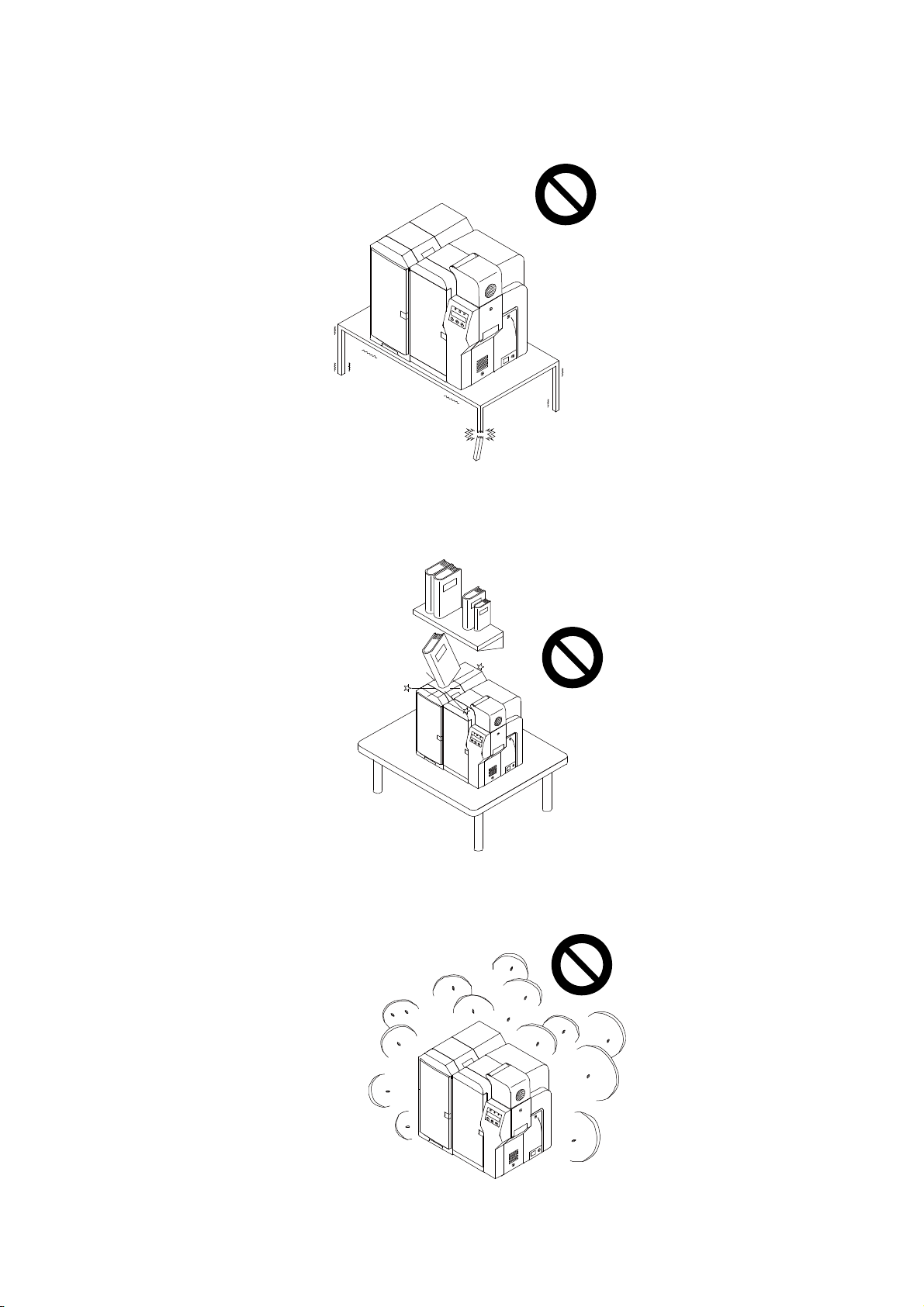
■Do not install at high humid and dusty place.
The place where water such as rain or other liquid may sprinkle.
Dusty place. It may cause a fire and/or electric shock.

5
(4) Electrical rating of power supply for this unit is shown on the rear cover.
Connect the power source correctly as described in the page 14 of this manual.
■If connected to the power source which is different from the specified rating or the
power source of less capacity, it may cause a fire or electric shock.
■If the machine will not be used for a long period, remove the power plug from
the wall outlet.
Even if the power switch is turned off, the unit is still connected to the power source.
It may be affected by thunder etc. and cause a fire unless the power cord is disconnected
from the wall outlet.
If the following occurs, stop operation immediately, disconnect the power plug and call
the dealer. Do not resume to use till the service person completes the inspection and
servicework.
●Smoke, unusual smell, abnormal sound, etc. are detected.
●The unit fell off the table or is subjected to a physical shock.
● Water etc. are sprinkled.
(5) Do not turn off the power or open covers while the machine is running
Do not turn power off or open covers while printing, otherwise a card
remaining in the heat roller unit could not be ejected automatically by
deforming when re-turn power on.
If a power cut occurs while printer working, open the front cover and
checkwhetheracardisintheHeatRollerunit.

6
Memo

7
Section 2: Preparation
Check the contents of the package.
●Check that there is no damage on the unit during transportation. If any damage is found,
please contact the dealer immediately.
●Check that the following are included:
Power cable.
Ribbon take-up spool
Operating manual
A cushion pad is inserted inside the unit to protect the heating lamp from a shock
during transportation. Remove the pad before using following the instruction in
page 13th.
Caution

8
Memo
9
Names of Parts
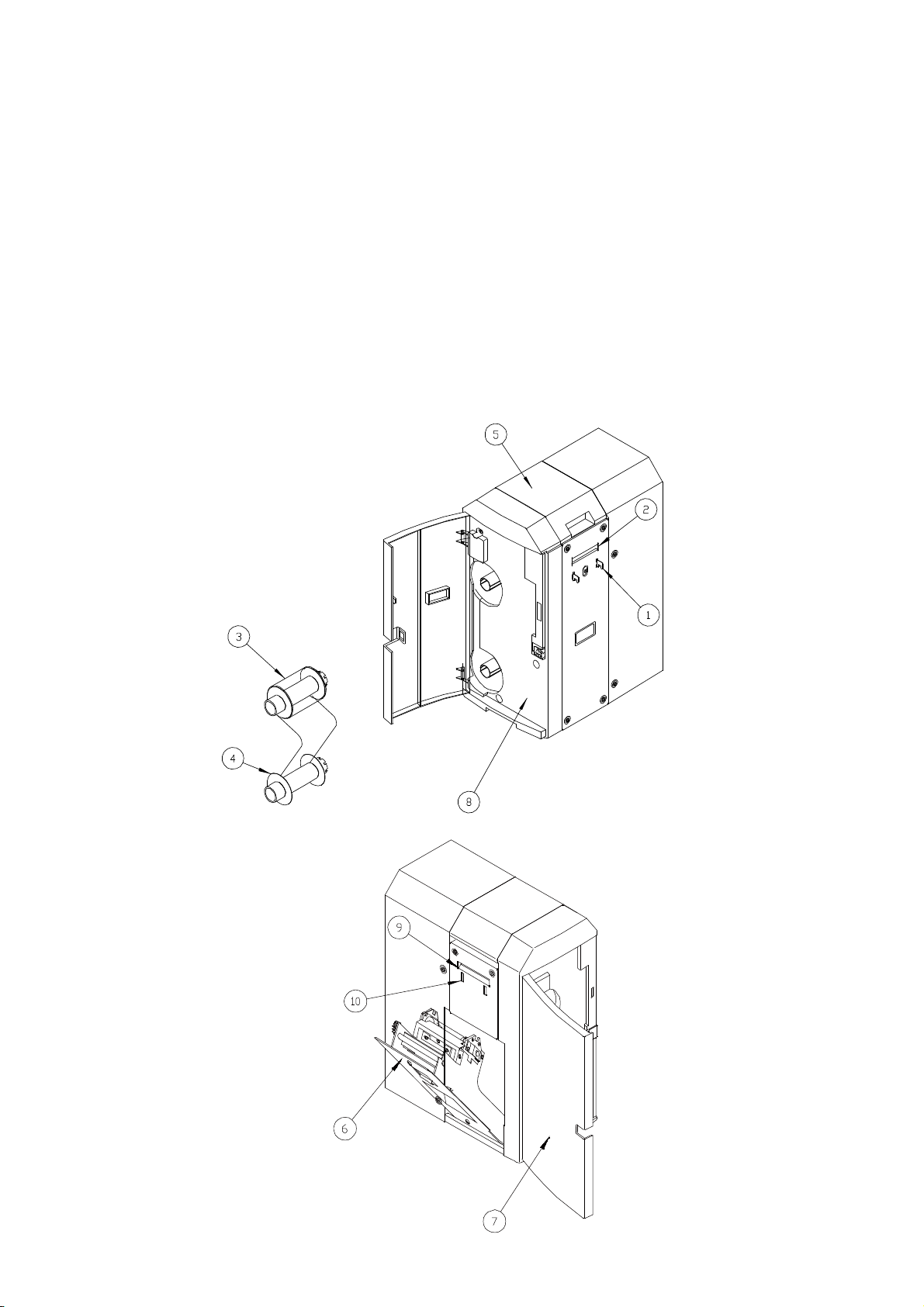
<PR-L151 (MODEL No. PR5302)> (Front Side, Right & Left Side)
1: Printer joint hook
2: Card entrance
3: Ribbon feeding spool
4: Ribbon take-up spool
5: Top cover
6: Side Cover
7: Front Access Cover
8: Front Cover
9: Eject Card Exit
10: Stack-Box Installing Hole
10
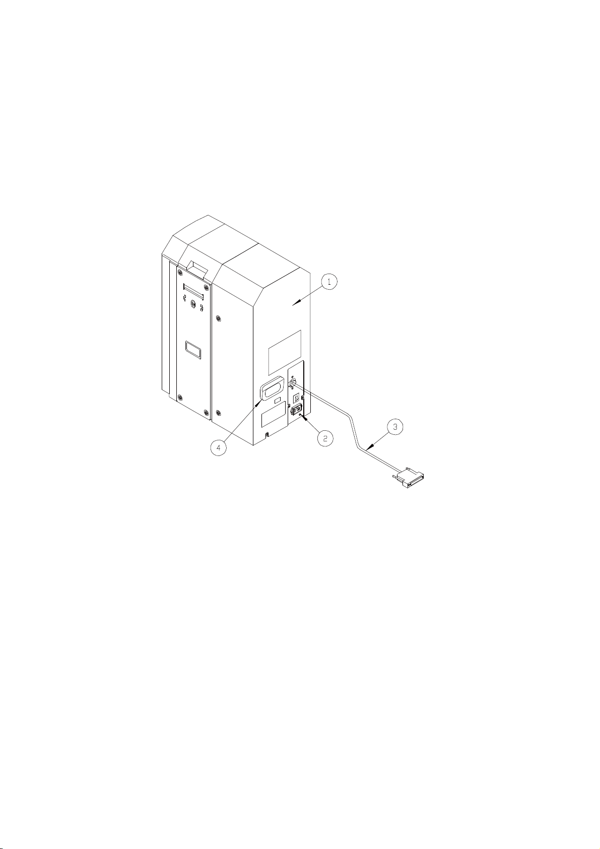
Names of Parts
<PR-L151 (MODEL No. PR5302)> (Rear Side)
1: Rear cover
2: Power cord receptacle
3: Printer connecting cable
4: Handle
11
Section 3: Installation
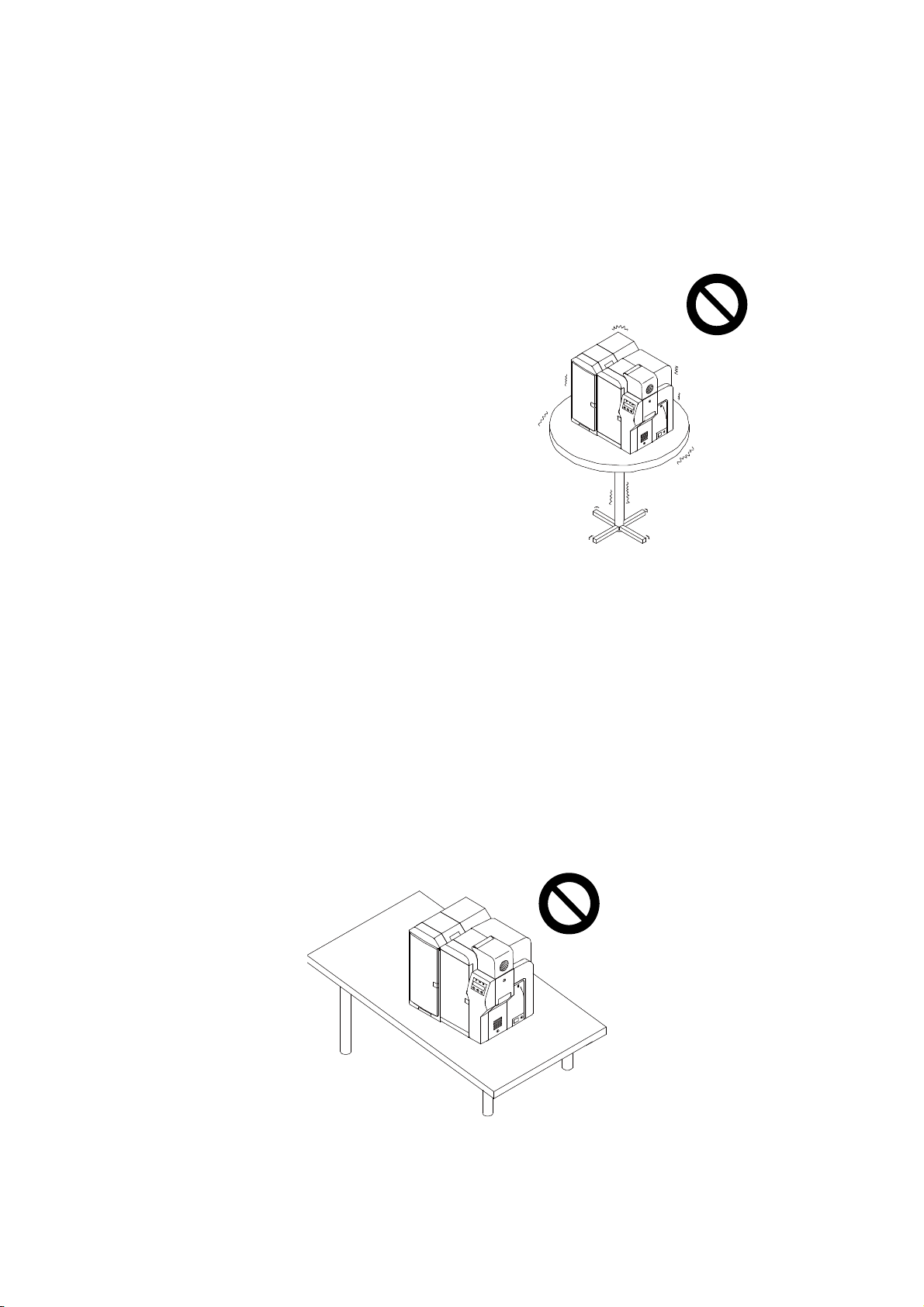
a) Place to install
Select the place as described below:
●Select and install on the rigid table or floor on the same plane as the printer, which is
free from vibration or shock.
●The place where the environment can be controlled as specified in the specification.
Temperature: 10-35℃(50 - 95°F)
Humidity: 35-80%
Do not install in such place as following:
●Slanted and/or uneven surface.
12
●Weakly structured table or floor which cannot sustain the weight of the unit.
●Table or floor which may be subjected to a drop shock of something.
●Place with much dust and high humid.

13
b) Installation procedure
(1) Open side cover
(2) Remove lamp protection pad before connecting to the power source.
(3) Turn off the power of the printer. (PR-C151 (Model No. PR5350) )
Turn off the power switch of the printer and confirm that the Power LED on the
operation panel of the printer is off.
(4) Combine the Heat Roller unit to the printer. (PR-L151 (Model No. PR5302))
Remove the stacking box of the printer.
Insert the printer joint hook located on the right side cover of the unit into the
stacking box hole located on the left side cover of the printer in the direction as
shown by the arrow mark.
After combining this unit with the printer, make sure that all four legs of both this unit
and the printer are supporting the bodies of the units. If any one leg is found not
supporting, check whether the surface of the desk is even or not slanted, or the
combination hook is firmly inserted, etc. and remove the cause after determining.
(5) Attach the stacking box to the card exit of this Heat Roller unit.
Insert the stacking box removed from the printer into the stacking box mounting hole.
Important

14
(6) Check the power source before connecting the power cord to the wall outlet.
●Select the correct power supply wall outlet to connect the cord of this unit.
Check and confirm whether the rating of the power source matches with the rating
which is indicated on the rating plate on the back of the unit.
If the rating of the outlet cannot be confirmed, ask your dealer before connecting
the power plug.
●Select the outlet location for easy plugging of the cord.
●If extension cord needed, use the cord with higher rating than the rating of the unit.
The rating of the extension cord is:
125V 10A for the 100 - 120V series unit.
250V 10A for the 200 - 240V series unit.
Using the cord with less than the rating may cause abnormal heat or fire.
●Use the outlet with the earth pole.
(7) Plug-in the power cord.
●Do not handle the power cord with wet hands as it may result in electric shock.
●Do not bend the power cord too tightly, place anything on it or place at near the
heat emitting objects.
●Connect the earth line of the power cord to the earth terminal of the outlet without fail.
(8) Connect the printer connecting cable. (PR-L151 (Model No. PR5302) )
First, confirm that the power switch of the printer is off (Power LED of the control
panel of the printer is off) and then, connect the cable to the optional unit connector at
the backside of the printer.
There is a power supply from the printer (DC 5V & 24V). If the cable is connected
while the power source to the printer is on, it may cause a trouble on the unit.
Firmly tighten the screws of the plug of interface cable to prevent unexpected trouble.
Important
15
Section 4: Replacing the ribbon

16
1. Ribbon to be used
Please use the ribbon specified by the dealer only.
There are two types of ribbons, hard coat type and soft coat type.
The unit will not function if the ribbon which is not specified is used.
Fire or other trouble may be caused depending on the kind of the ribbon used.
2. Timing of the ribbon exchange
The ribbon for this unit must be exchanged as a consumable supply at the following
occasions:
●When the unit is first used.
The ribbon is not loaded when the unit is shipped from factory.
●When the ribbon is finished
●When changing the type of ribbon
Important

17
3. Preparation for changing the ribbon
(i) Remove the adhesive tape of the ribbon.
Peel off the adhesive tape on the end of the new ribbon roll.
(ii) Place the feed spool side be side with the take-up spool in the same direction
as shown in the fig.
Coupling holes of both take-up spool and feed spool must be in the same direction.
If the unit is used for the first time, use the empty take-up spool which is included in
the shipping carton. After second time on, use the feed spool which has become
empty, as the take-up spool. ( The feed spool and the take-up spool are the same )
(iii) Attach the end of the ribbon onto the take-up spool with adhesive tape along
the groove of the spool.
Align the edge of the ribbon against the longitudinal groove on the spool and attach.
Important
Caution

18
If the end of the ribbon is not aligned correctly against the groove it may cause a
failure in take up or coating.
(iv) Turn on the power of the printer.
Power LED lamp on the operation panel turns on.
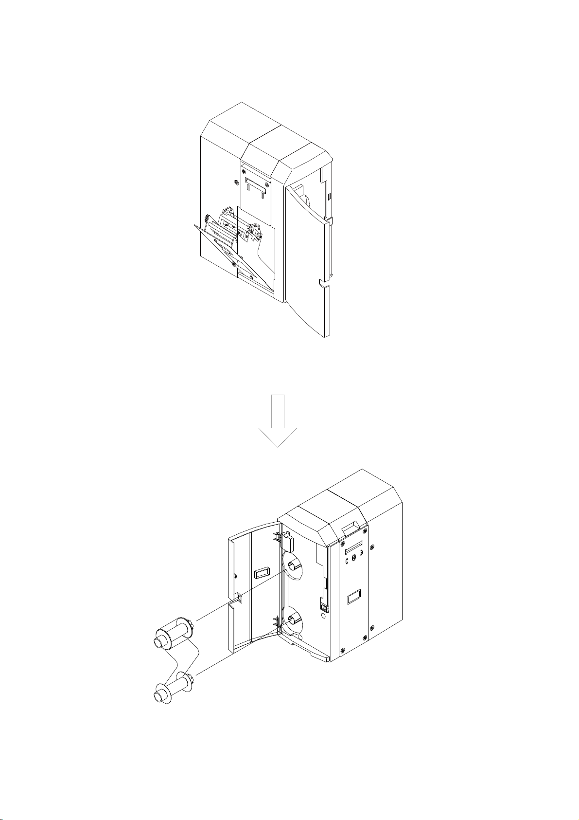
(v) Open side cover
4. Loading the ribbon
While exchanging the ribbon, the Heat Roller (150℃(302°F)) is exposed.
Do not put your fingers in this area to avoid getting burned.
Carefully proceed the ribbon exchanging in the following steps.
(i) Open the front access cover.
Gently press the center part of the cover. Then the cover opens.
(ii) Load the ribbon
●Hold take-up and feed spools with both hands, the coupling holes toward the unit as
shown in the fig.
●Slowly insert the spools onto the guide-pins of the unit.
If the spools are not inserted smoothly, the ribbon or spools may be conflicting
with some parts inside the unit. Pull out and try again.
●Insert the spools till they are set firmly
Important
Important
Caution
This manual suits for next models
1
Table of contents


