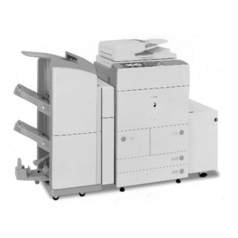
Sharp SF-S55N User manual

SF-S55N
SERVICE MANUAL
MODEL SF–S55N
Be sure to use only the genuine parts so as to ensure safety and reliability.
The parts marked with îare important for safety. When replacing these parts, be sure to use the
specified parts so as to keep safety and performance of the machine.
CONTENTS
[ 1 ] SPECIFICATION …………………………………………………1−1
[ 2 ] UNPACKING AND INSTALLATION………………………………2−1
[ 3 ]
EXETERNAL AND INTERNAL STRUCTURE
………………………3−1
[ 4 ] DISASSEMBLY AND ASSEMBLY ………………………………4−1
[ 5 ] ADJUSTMENT ……………………………………………………5−1
[ 6 ] DIAGNOSTICS ……………………………………………………6−1
[ 7 ] TROUBLESHOOTING ……………………………………………7−1
[ 8 ] MAINTENANCE ……………………………………………………8−1
[ 9 ] OPERATION ………………………………………………………9−1
[10] CIRCUIT DIAGRAM ……………………………………………10−1
●PARTS GUIDE ……………………………………………………11−1
CODE : 00ZSFS55NSM1J
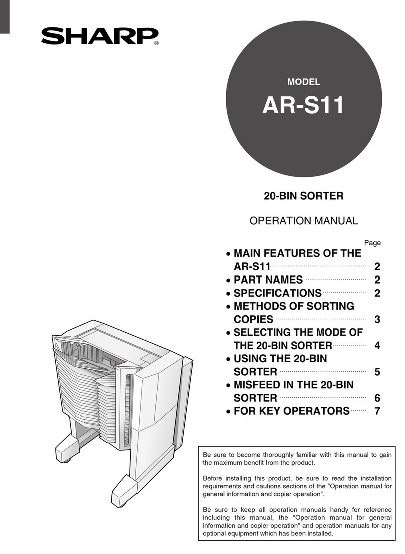
20-BIN STAPLE
SORTER
SHARP CORPORATION

[1] SPECIFICATION
1. Operation specification
(1) Type
• 20-bin staple sorter
• Stacking system
• Face-up stacking, sequential opening in order of bin
transfer by lead cam
• To-and-fro sorting (when RADF is used)
• Stacking paper
• 64 to 200 g/m2paper
• Stacking paper sizeA5/8-1/2" x 5-1/2" to A3/11" x 17"
• Number of bins
20 bins + Non-sort tray
(2) Modes
a. Stacking mode
1) NON-SORT MODE : Unless SORT, GROUP or
STAPLE mode has been
set, all the prints are
unloaded to the non-sort
tray.
2) SORT MODE : Gathering of prints is performed
automatically.
3) STAPLE SORT MODE : After completion of SORT
mode the stapling is
performed automatically.
4) GROUP MODE : The prints of one original are
unloaded to the same bin.
b. Staple mode
1) AUTO STAPLE MODE : Full-automatic stapling in
the STAPLE SORT mode
2) MANUAL STAPLE MODE : Stapling initiated by
turning on the
STAPLE key after
completion of SORT
mode
3) HAND-INSERTED STAPLING :
Simple stapling initiated by
turning on the STAPLE key after
loading paper in the uppermost
bin
c. Sort order
1) Original stand copy : Once to-and-fro sort (always
return to the 1st bin)
2) Using RADF : To-and-fro sort
(3) Stacking volume
Note : The stacking volume of STAPLE SORT conforms
to the stacking volume of SORT. However,
STAPLE SORT is disabled for paper having a
width less than 210 mm or a length less than 182
mm.
Note : Up to 10 sheets of special paper can be stacked
for NON-SORT.
※Special papers: Mother print paper, OHP paper,
thick paper (81 to 200 g/m2)
However, front covers and back covers and
interleaving papers which are thick papers can be
sorted.
(4) Stacking volume overflow
1) NONSORT : BOOK mode.
2) SORT : When 26 sheets of large size paper or 51
sheets of small size paper are loaded in the
BOOK mode even when DF is used, the
sorter OVERFLOW signal is output.
(Remove paper, and press the COPY
button to re-start.)
3) GROUP : Regulation by the print quantity at the
main unit side (inhibition item setting)
(5) Bin number OVERFLOW
SORT/GROUP mode Paper size A4, 8 1/2" x 11", B5
1) Front side taking-out ON
: Suspension after completion of processing of set
quantity for 40 bins (for all sizes)
Automatic start after removal of paper
2) Front side taking-out OFF
: Suspension after completion of processing of set
quantity for 20 bins (for all sizes)
Re-start is enabled after removal of paper.
Other sizes
: Suspension after completion of processing of set
quantity for 20 bins (for all sizes)
Re-start is enabled after removal of paper
1−1
SF-S55N
Paper size Sort Group
Non-sort
A3/11"×17" 25
B4/8 1/2"×14" 25
A4 portrait/8 1/2" x 11" portrait
B5 portrait 250
A4/8 1/2"×11" 50
B5/A5 30
8 1/2"×5 1/2"
(20) Stapling position (single stapling)
(6) Total stapling time (20 bins)
1) Single stapling: Approx. 27 seconds (inch. pre-
stapling adjusting time, approx. 4 seconds)
2) Double stapling: Approx. 52 seconds (incl. pre-
stapling adjusting and stapler shift time approx. 5
sec.)
(7) Bin return time (20 to 1 bin home position)
Approx. 11.5 sec (book copy state, multi-load 2nd
copy) Approx. 16 sec (others)
(8) Paper detection: Provided
(9) Limit-less sort: Possible
(10) In-bin sort (multi-load)
Up to 2 copies in the lateral feed mode (A4, B5, 8
1/2" x 11")
However, paper size on all bins must be the same,
and the total quantity of paper sheets in each bin
must not exceed 50.
(11) Front side taking-off
In the lateral feed mode (A4, B5, 8 1/2" x 11") only
(12) Control panel
Manualstaplingbutton,Frontaccessbutton,
Bin-up/Bin-downbutton,Stapleposition
selectingbutton
Display
Manual stapling: Enable/Disable (Enable while LED is
lighting)
Display on main unit control panel: Nonexistence of
staples, indication of staple position
(13) Operating sound
60 db or less
(14) Stapling section
1) Stapling direction
2) Rotating cam driving-in system
3) Maximum stapling thickness: Bundle thickness 5.5
mm or less
80 g/m2paper 48 sheets + 200 g/m2paper 2 sheets
(15) Staple charging system
Exclusive-use staple cartridge system (5,000 staples)
(16) Detection of nonexistence of staple: Provided
(17) Stapling-enable size
A3, A4, B4, B5, A4 portrait, 11" x 17",
8 1/2" x 14", 8 1/2" x 11", 8 1/2" x 11" portrait
(18) Manual stapling
Possible (however, one innermost part cannot be
stapled)
(19) Staple specification
Automatic and manual
1−2
SF-S55N
A3, B4, B5, A4 portrait,
11 x 17, 8 1/2 x 14, 8 1/2 x 11,
8 1/2 x 11 portrait
Front side
45°
5±2.5mm
Rear side
A4 portrait 8 1/2 x 11 portrait
8 1/2 x 14
5.75±2.5mm
4.5±2.5mm
11×17
81/2×11
B4, B5
A3, A4
5±2.5mm 5±2.5mm
5.75±2.5mm
73±4.5mm 74.4±4.5mm
62.5±4.5mm 62.5±4.5mm
82.5±4.5mm 82.5±4.5mm
5.75±2.5mm
5.75±2.5mm5.75±2.5mm
Stapling position (double stapling)

SF-S55N
2. Electric specification
1) Input voltage: DC 24V
2) Maximum power consumption: 100W or less
3) GS (EN60950)
4) VCCI Class 1, FFC/IC Class A
5) CE (EN55022, EN50082, EN60950)
3. Overall size and weight
1) 591W x 609D x 960H mm
2) Approx. 56 kg
4. Environment specification
Environment ensuring normal operation
10˚C to 32.5˚C
15% to 85%RH
0.7 to 1.0 atm (corresponding to altitude 3,000 to 0 m)
Storage and transportation environment
Any defects must not appear during storing for 10 days in
packaged state in the following environmental conditions.
-20˚C, 240 hours
40˚C, 90%, 240 hours
5. Others
Expendables
Staple SF-SC11
1−3
Sorter mode
Type of paper Size NON-SORT (STAPLE) GROUP
SORT
Paper for PPC A3, B4, A4, B5, A5Note ◯◯◯
64 to 80 g/m211"×17",8 1/2"×14" ◯◯◯
8 1/2"×11",8 1/2"×5 1/2"
Recycled paper for PPC A3, B4, A4, B5 ◯◯◯
Color paper for PPC B4, A4 ◯◯◯
Mother print paper A3, B4, A4, B5 ◯
Paper for OHP A4, 8 1/2"×11" ◯
Government-printed postcard A6 portrait ◯
Thick paper A3 ,B4, A4, B5 ◯△
81 to 200 g/m28 1/2"×11"
Label paper A4 ◯
Note: Paper having a width less than 210 mm or a length less than 182 mm cannot be stapled.
Plain pape Special paper

[2] Unpacking and installation
1. Unpacking
2−1
SF-S55N

1−5
SF-S55N

[2] Installation
1. Parts list
SF-S55N
2−2
1.0m
1.5m
Before installation.....
Be sure that you have plenty of room
around the copier for work space.
Install the copier on a flat floor.
Remove the securing fixtures. Fit the slot cover.
Screws Screws
Securing fixture Slot cover screws
Slot cover
Remove the 4 screws fixing the securing fixtures
at the bottom of the sorter, and remove the
securing fixtures.
Fit the slot cover to the bottom of the sorter in the
position shown in the figure, and secure it with
the 2 slot cover screws (M4x12).
OGZXB
47401207

2. Unpacking
SF-S55N
2−3
Remove all the securing tape and securing materials.

FOR USE WITH COPIER MODEL SF-2052
SF-S55N
2−4
Slot cover screws
(M4 x 12): 2
Sorter mounting plate screws
(M4 x 16): 2 Slot cover: 1
Stapler jam release tool: 1
Sorter mounting plate: 1
Rail: 1
Rail mounting plate: 1
Operation instruction label Stapling location label
(for copier): 1 Stapling location label
(for RADF): 1
Parts to be used
Rail mounting plate screws
(M4 x 14): 2 Rail screws A
(M4 x 10): 2 Rail screw B
(M4 x 10): 1
Support guide: 1
Stuck to the lower part of the front cover
Used only in 200 V areas
and agent areas (CE)
Grounding spring screw
(M4 x 8)
Grounding spring
(A) (B)
(A) (B)
OGZXB27401407 OGZXB67401006 OGZXB27401006
OGZXB47401207
OGZAA12311000
OGZFZ62133000 OGZFE02132000

4. Installation (mounting)
SF-S55N
2−5
Adjust the position of the casters.
• Loosen the caster nuts (4) and shift the caster positioning
plates one notch, as shown in the illustration.
Caster nuts Caster nuts
Standard caster position
Caster positioning plate
Standard caster position
Adjusted caster position

SF-S55N
2−6
Unplug the copier's power cord before carrying out the following procedure.
Mounting of the staple sorter onto the copier.
1. Attach the sorter mounting plate.
2. Attach the support guide.
Sorter mounting plate screws
Sorter mounting plate
Attach the support guide by attaching its pawls (2
locations) to the inside of the copier's paper output
section.
Pawls
Support guide
Cut portions
Attach the sorter mounting plate with the 2 sorter
mounting plate screws (M4x16 with washer).
At this time, the sorter mounting plate screw holes
are elongated; tighten the screws so that the
sorter mounting plate hangs down in its lowest
position, in the way shown in the figure.
3. Cut off the cut portions of the copier.
Remove the 2 cut portions from the lower part of
the copier's left cabinet panel.
OGZAA12311000

SF-S55N
2−7
6. Attach the rail to the sorter.
4. Fit the rail mounting plate onto the rail.
Rail mounting plate
Rollers
Rollers
Rail
Rail
Rail mounting plate
5. Attach the rail mounting plate to the copier.
Insert the rail under the copier as shown in the
figure and secure the rail mounting plate to the
copier with two rail mounting plate screws (M4 x
14).
Rail mounting plate screw
Insert the rail between the rollers on the rail
mounting plate as shown in the figure.
Fit the rail onto the rail mounting angle which is
fitted at the bottom of the sorter, and secure the
rail with the two rail screws A (M4x10) and the rail
screw B (M4x10).
Rail mounting angle
Rail screw B
Rail
Rail screws A
Rail screws A
Grounding spring (B)
Used only in 200 V areas and
agent areas (CE)
Grounding spring screw (B)
OGZXB
27401407
OGZXB-7401006
OGZXB67401006

SF-S55N
2−8
8. Connect the sorter connector.
Sorter connector
Connector on copier
Sorter connector cover
7. Confirm that the staple sorter can be attached and detached correctly.
9. Attach the grounding spring. ( only in 200 V areas and agent areas [CE] )
Cut off the cut portion (1 location) from the upper
part of the copier's left cabinet panel.
Then secure the grounding spring included in the
package using the grounding spring screw (M4 x
8).
Cut portion
Grounding spring (A)
Grounding spring screw (A)
Remove the sorter connector cover from the
copier's rear panel.
Then connect the sorter connector to the
connector
Sorter mounting plate
(1) Latch and unlatch the staple sorter from the
copier to confirm that it moves smoothly.
(2) Confirm that the staple sorter locks into place
beside the copier.
If not, adjust the height of the sorter mounting
plate until the staple sorter locks securely into
place.
• If the above operation fails to make the staple
sorter lock into place, the floor is probably not
level.
Alter the positions of the casters on the bottom
of the sorter to adjust levelness.

SF-S55N
2−9
10. Affix the stapling location labels.
12. Set the mode
・Perform the following key operations on the copier to set the mode.
1
C026 0
Align the right and bottom edges of the operation
instruction label with the control unit's ribs, and
stick the label on in that position.
11. Affix the label to the operation unit.
Operation instruction label
Affix the stapling location labels as shown in the figure.
Stapling location label
(for copier) Stapling location label
(for RADF)
to set the mode.
Insert the copier's power plug into a grounded outlet, and turn the power
switch on. Then, follow the procedure below.
When this procedure is complete, see page 14, "Operation Check of Staple Sorter."
Select an adequate number from the display
of the operation panel using the 10-key pad.

SF-S55N
2−10
Rail screws A
(M4 x 10): 3 Rail screws B
(M4 x 10): 2
Slot cover screws
(M4 x 12): 2 Sorter mounting plate screws
(M4 x 16): 2
Slot cover: 1
Stapler jam release tool: 1
Sorter mounting plate: 1
Rail: 1 Rail mounting plate: 1
Operation instruction label Stapling location label
(for copier): 1 Stapling location label
(for RADF): 1
Parts to be used
Stuck to the lower part of the front cover
Used only in 200 V areas
and agent areas (CE)
Grounding spring
(A)
FOR USE WITH COPIER MODEL SD-2260/SD-2275

6. Staple setting
SF-S55N
2−11
Remove the 7 screws securing the upper left
cabinet panel to the copier, and take off the upper
left cabinet panel.
Remove the copier's power plug from its socket before carrying out
the following procedure.
1. Remove the upper left cabinet panel from the copier.
Mounting the staple sorter onto the copier
Screws (7 pcs.)
Upper left cabinet panel
2. Remove the lower left cabinet panel from the copier.
Open the toner collecting container cover and the
lower left cabinet panel and then remove the 1
screw for the lower left panel fixing wire.
Next, pull up the lower left cabinet panel to remove it.
Toner collecting
container cover
Lower left cabinet panel
Screw
Lower left panel
fixing wire

SF-S55N
2−12
5. Attach the rail to the sorter.
Rail mounting angle
Rail screw B
Rail
Rail screws A
3. Fit the rail mounting plate onto the rail.
Rail mounting plate
Rollers
Rail
Rollers
4. Attach the rail mounting plate to the copier.
Rail screw A
Rail
Rail screw B
Rail mounting plate
Insert the rail under the copier as shown in the
figure and secure the rail mounting plate to the
copier with one rail screw A and one rail screw B
(M4 x 10 each).
Rail screws A
Grounding spring (A)
Fit the rail onto the rail mounting angle which
isfitted at the bottom of the sorter, and secure the
rail with the two rail screws A (M4x10) and the
rail screw B (M4x10).
Insert the rail between the rollers on the
railmounting plate as shown in the figure.
Used only in 200 V areas
and agent areas (CE)

7. Removing the jammed staple
SF-S55N
2−13
Fit the copier's upper left cabinet panel, removed
in step 1, back in its original position, and secure
it with the seven mounting screws.
Reattach the lower left cabinet panel removed in
step (3) in its original position.
Then fit the lower left cabinet panel fixing wire back
in its original position using the 1 screw.
Close the lower left cabinet panel and the toner
collecting container cover.
6. Reattach the lower left cabinet panel.
7. Reattach the upper left cabinet panel to the copier.
Toner collecting
container cover
Lower left cabinet panel
Screw
Lower left cabinet
panel fixing wire
Screws (7 pcs)
Upper left cabinet panel
Remove the sorter connector cover from the
copier's rear panel.
Then connect the sorter connector to the connector
on the copier.
8. Connect the sorter connector.
Sorter connector
Connector on copier
Sorter connector cover

SF-S55N
2−14
(1) Latch and unlatch the staple sorter from the
copier to confirm that it moves smoothly.
(2) Confirm that the staple sorter locks into place
beside the copier.
If not, adjust the height of the sorter mounting plate
until the staple sorter locks securely into place.
• If the above operation fails to make the staple
sorter lock into place, the floor is probably not
level. Alter the positions of the casters on the
bottom of the sorter to adjust levelness.
Remove the 2 screws from the copier's upper left
cabinet panel. Attach the sorter mounting plate
with the 2 sorter mounting plate screws (M4x16
with washer).
The sorter mounting plate screw holes are
elongated; tighten the screws so that the sorter
mounting plate hangs down in its lowest position,
in the way shown in the figure.
9. Attach the sorter mounting plate.
10. Confirm that the staple sorter can be attached and detached correctly.
Upper left cabinet panel screws
Sorter mounting
plate screws
Sorter mounting plate
Standard point on scale
Sorter mounting plate

SF-S55N
2−15
1
C026
AUDIT
CLEAR 0AUDIT
CLEAR
• Operate the keys on the copier to set the mode.
Align the right and bottom edges of the operation
instruction label with the control unit's ribs, and
stick the label on in that position.
11. Affix the stapling location labels.
Insert the copier's power plug into a grounded outlet, and turn the power
switch on. Then, follow the procedure below.
13. Set the mode.
12. Affix the label to the operation unit.
Affix the stapling location labels as shown in the figure.
Stapling location label
(for copier) Stapling location label
(for RADF)
Operation instruction label
to set the mode.
When this procedure is complete, see page 14, "Operation Check of Staple Sorter."
Select an adequate number from the display
of the operation panel using the 10-key pad.
Table of contents
Other Sharp Printer Accessories manuals

Sharp
Sharp AR-F14N User manual

Sharp
Sharp AR-FN7 User manual

Sharp
Sharp AR-RB1 User manual

Sharp
Sharp AR-D28 User manual

Sharp
Sharp MX-LCX5 User manual

Sharp
Sharp AR-PB8 User manual

Sharp
Sharp MX-B201D User manual

Sharp
Sharp FO-59A4 Instruction Manual

Sharp
Sharp AR-NB3 User manual

Sharp
Sharp ARNC5J User manual
Popular Printer Accessories manuals by other brands

Epson
Epson T606700 Material safety data sheet

Toshiba
Toshiba KD-1025 Service manual

Epson
Epson Stylus Photo 790 instructions

Sawgrass Technologies
Sawgrass Technologies Sublijet IQ R1800 installation instructions

Roland
Roland PNS-52 Assembly instructions

Xerox
Xerox 3100MFPX - Phaser B/W Laser installation instructions