Nittan evolution EV-P User manual

Document No. NISM/EV-P/02
Date: FEBRUARY 2012
evolution
EV-P
ANALOGUE ADDRESSABLE
PHOTOELECTRIC SMOKE SENSOR
INSTRUCTION MANUAL
LPCB REF: 041f/01
Quality System Certificate No. 041
Assessed to BS EN ISO 9001:2008
Hipley Street, Old Woking, Surrey, England, GU22 9LQ. UK
Tel: +44 (0) 1483 769555 Fax: +44 (0) 1483 756686 Web Site: www.nittan.co.uk E-mail: sales@nittan.co.uk

evolution
EV-P
ANALOGUE ADDRESSABLE
PHOTOELECTRIC SMOKE SENSOR
Ref No:
DATE:
PAGE:
NISM/EV-P/02
FEBRUARY 2012
ISSUE:
INSTRUCTION MANUAL
evolution.....
1 of 5 02
The EV-P advanced analogue addressable combined photoelectric and
heat sensor forms part of a brand new range of analogue addressable fire
sensors from Nittan UK called
evolution
.
The EV-P together with the EV-H, EV-PH, and EV-DP are all elegantly
designed, low profile fire sensors which are aesthetically pleasing, thus
enabling them to blend unobtrusively into modern working environments.
The
evolution
analogue addressable range all feature the very latest
technological advancements such as ASIC design, increasing reliability and
performance.
evolution
...........
- BRINGING STYLE INTO FIRE DETECTION SYSTEMS
Changes
are
subject
to DCRN.

evolution
EV-P
ANALOGUE ADDRESSABLE
PHOTOELECTRIC SMOKE SENSOR
Ref No:
DATE:
PAGE:
NISM/EV-P/02
FEBRUARY 2012
ISSUE:
INSTRUCTION MANUAL
2 of 5 02
CONTENTS:-
Section 1 - Introduction - Page 2
Section 2 - SensorModels - Page 2
Section 3 - BaseModels - Page 2
Section 4 - Installation - Page 3
Section 5 - Maintenance &
Cleaning - Page 3
Section 6 - Specifications - Page 4
Section 7 - Environmental
Parameters:- - Page 4
- Temperature - Page 4
- Humidity - Page 4
Section 8 - EMC - Page 5
Section 9 - Address Setting - Page 5
Section 10 - Connections - Page 6
Section 11 - Dimensions - Page 6
Section 12 - Heat Response Graph - Page 7
Section 1 - INTRODUCTION
The EV-P is an attractively-styled, low profile
photoelectric smoke sensor for use with Nittan
'
evolution
' protocol control panels.
EV-P features:
* Low profile, stylish appearance
* Soft addressing
* Low monitoring current
* Supplied with protective dust cover
* OMNIVIEW
TM
360
o
LED fire alarm indicator
* Remote indicator output
* 'Base Control' auxiliary output
* Compatible with UB-4-EV and STB-4SE-EV
bases
*Non-polarisedterminals
* Optical sensor, detecting visible particles of
combustion
Section 2 - SENSOR MODELS
The EV-P photoelectric smoke sensor has two terminals
for connection onto the two wire loop. The remaining
terminals provide a switched current sink function which
operates when the sensor goes into alarm condition,
suitable for the operation of an auxiliary function such as a
remote indicator. Terminal 3 (RIL) is limited to 3mA.
Terminal 2 (Base Control) is not current limited.
Section 3 - BASE MODELS
A variety of bases are available for use with the EV-P
sensor. It is important to use the correct base for each
application. The available base models are:
i) UB-4 base: for standard use with EV-P sensor.
ii) UB-4-EV base: for standard use with EV-P sensor.
iii) STB-4SE-EV base: Similar to UB-4-EV base, except
deeper.
Changes
are
subject
to
DCRN.

evolution
EV-P
ANALOGUE ADDRESSABLE
PHOTOELECTRIC SMOKE SENSOR
Ref No:
DATE:
PAGE:
NISM/EV-P/02
FEBRUARY 2012
ISSUE:
INSTRUCTION MANUAL
3 of 5
02
Section 4 - INSTALLATION
In normal use, the EV-P smoke sensor will be installed at
ceiling level. Pass the field wiring through the cable hole
in the centre and from the rear of the base. Offer up and
affix the base to the ceiling or conduit fitting with screws
via the base mounting holes. Connect the field wiring to
the base terminals, as detailed on page 6 making sure the
wiring does not obstruct fitting of the sensor head. Fit the
sensor head by inserting it into the base and turning
clockwise until the notch in the sen- sor's rim aligns with
base locking screw. The OMNIVIEW
TM
360
o
LED alarm
indicator permits visibility from any angle.
Note: The address must be set before the sensor is
fitted into place.
Fit the plastic dust cover supplied over the sensor to
keep out dust etc, until the system is commissioned. If
the dust cover is not fitted and the environment is slightly
dusty, such as when building work is being completed, for
example, problems of false alarms are likely to occur after
commissioning unless cleaning of the sensor is
undertaken. At commissioning, the dust cover should
be removed and discarded.
NOTE: THE PLASTIC DUST COVER MUST BE RE-
MOVED FROM THE SENSOR IN ORDER FOR THE
SENSORTOFUNCTION CORRECTLY.
Section 5 - MAINTENANCE AND
CLEANING
Maintenance:
The EV-P sensor is a high quality product engineered for
reliability. If proper preventative maintenance is not
carried out, there is a likelihood of malfunction, including
false alarms.
Servicing:
Servicing of the system should be carried out in accord-
ance with the requirements of BS 5830 Part 1, Fire
Detection and Alarm Systems for Buildings: Code of
Practice for System Design, Installation and Servicing.
Routine Inspection
i) Ensure the sensor head is secure and undamaged.
ii) Check the smoke entry apertures are in no way
obstructed.
iii) Ensure that the surface of the sensor's outer cover is
clean. If there are deposits due to the presence of oil
vapour, dust etc, then the sensor should be cleaned in
accordance with the cleaning instructions detailed later in
this manual. It may be advisable to ensure that such
cleaning is conducted regularly in future.
iv) Ensure that no equipment which may generate exces-
sive heat has been installed in the vicinity of the sensor
since the last routine inspection. If such equipment has
been installed, then you should notify the Fire Safety
Officer or other competent authority that its presence may
cause false alarms.
v) Ensure no equipment which may generate combustion
products or fine airborne particles has been installed in the
vicinity of the sensor since the last routine inspection. If
such equipment has been installed, then you should notify
the Fire Safety Officer or other competent authority that
its presence may cause false alarms.
OperationalTest
The purpose of the Operational Test is to confirm the
sensor’s correct operation in response to a smoke and/or
heat condition.
Note: When carrying out site testing of Analogue
Addressable Evolution sensors, the CIE shall be set to
test mode prior to beginning the tests.
i) Take any necessary precautions at the control panel to
limit the sounding of the alarm sounders/bells and any fire
service summoning device.
The maintenance procedures described below, should be
conductedwiththefollowing frequency:
One month after installation: Routine Inspection and
every 3 months after.
Every 6 months: Operational Test.
Every 12 months: Functional Test and
Cleaning.
All above frequencies of maintenance are dependent on
ambient conditions.
ii) To test the optical sensor, introduce a discrete amount
of smoke into the detector head, e.g. using a
'No Climb - Solo' smoke test head. Check that the
sensor gives an alarm condition within 15 seconds.
Check the LED indicator on the EV-P sensor illumi-
nates and any remote indicator LED fitted also illumi-
nates.
iii) After the sensor has given the alarm condition, reset the
sensor from the control panel. It may be necessary to allow
a short time to elapse before resetting the sensor, to allow
any residual smoke from the test to disperse.

evolution
EV-P
ANALOGUE ADDRESSABLE
PHOTOELECTRIC SMOKE SENSOR
Ref No:
DATE:
PAGE:
NISM/EV-P/02
FEBRUARY 2012
ISSUE:
INSTRUCTION MANUAL 4 of 5 02
iv) Before proceeding to the next sensor, ensure that the
sensor previously tested does not re-operate due to the
presence of residual smoke.
FunctionalTests:
The functional test checks the sensors operation. These
detectors may be returned to our factory for Functional
Testing.
Cleaning:
Note: The sensor head should NOT be disassembled.
i) Carefully remove the sensor from its base.
ii) Use a soft, lint-free cloth, moistened with alcohol for
sticky deposits, to clean the plastic cover.
iii) Using a soft bristle brush (e.g. an artists paintbrush)
carefully brush between the vanes and thermistor in a
linear motion away from the apertures on the plastic
case.
iv) Ensure that no debris is left on or around the thermis-
tor once cleaning is complete.
v) If the unit needs further cleaning or is damaged or
corroded, please return the complete detector to Nittan
UK. for service.
Section 6 - SPECIFICATIONS
ModelReference: - EV-P
ComputerReference: - F14N82100
SensorType: Photoelectric
smoke sensor
Sensitivity: - 3 levels can be
selectable for smoke
and rate of rise for heat.
OperatingCurrent: - 200
µ
amps
fire alarm (LED on)
5.2mA
Sensitivity: - EN54 Part 7:2000
Mass: - 118g (excluding base)
Charging Time: - 20 seconds
AmbientTemperature
Range: - -10
o
C to +55
o
C
IPRating: - 42
Section 7 - ENVIRONMENTAL
PARAMETERS
TemperatureConsiderations:
Over the range from -10
o
C to +55
o
C.
Humidity:
Relative Humidity of up to 95%, measured at
50 deg. C., non condensing.
Section 8 - EMC
Installation
The installation shall be in accordance with the regula-
tions either of the approval body for an approved system,
or otherwise, to the national code of practice/regulations
for the installation of the fire alarm system, e.g. BS 5839
part 1.
ElectromagneticCompatibility(EMC)
On a site where there is an unusually high level of poten-
tial electrical interference, e.g. where heavy currents are
being switched or where high levels of R.F. are prevalent,
care then must be taken in the type and routing of cables.
Particular care should be given to the separation of zone
wiring from the cable carrying the interference.
Section 9 - ADDRESS SETTING
Use EV-AD2 Programmer for setting the address of all
devices prior to installation.
evolution
EV-P
ANALOGUE ADDRESSABLE
PHOTOELECTRIC SMOKE SENSOR
Ref No:
DATE:
PAGE:
NISM/EV-P/02
FEBRUARY 2012
ISSUE:
INSTRUCTION MANUAL
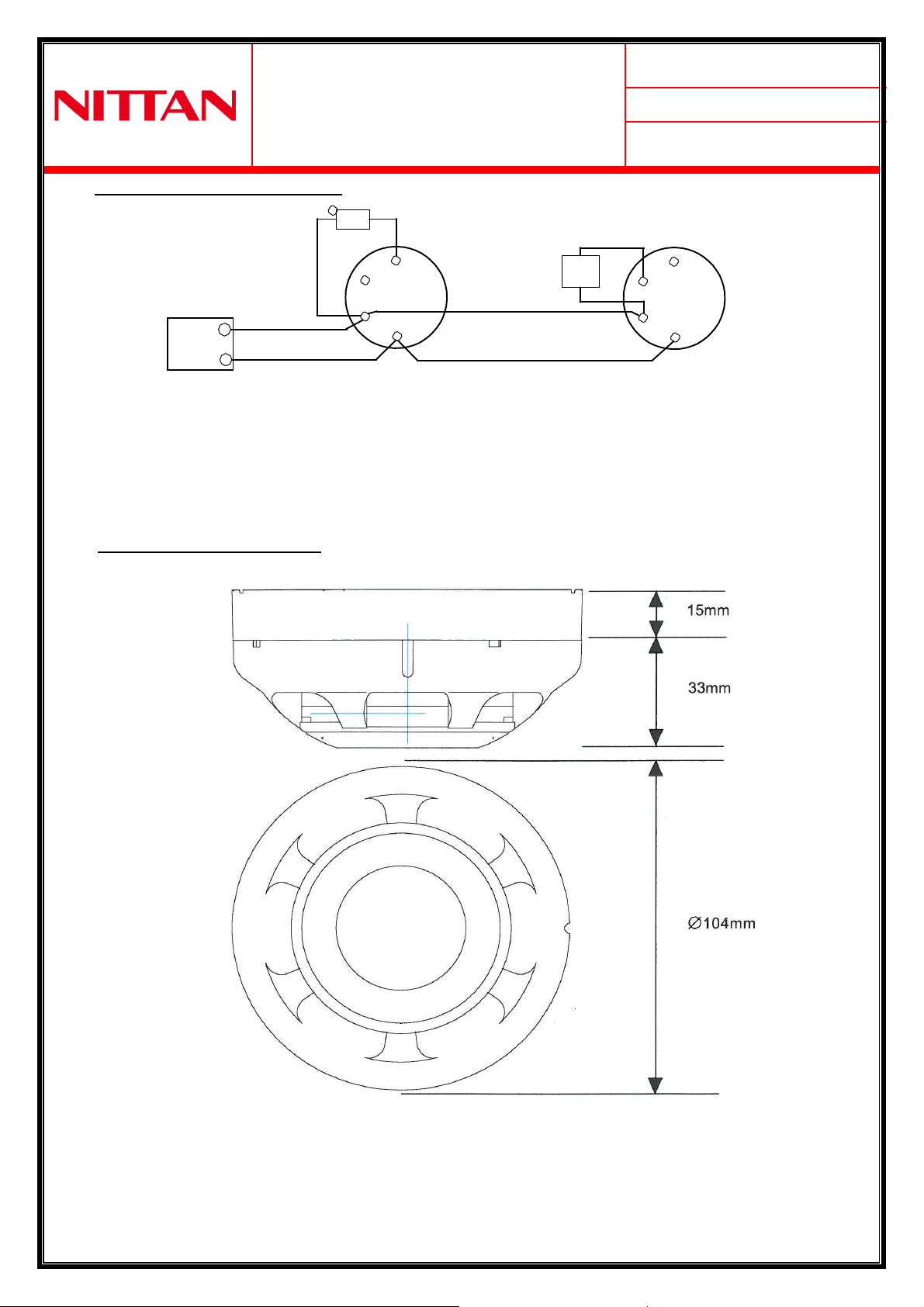
Section 10 - CONNECTIONS
+
5 of 5
02
RIL must be LED type
RIL
Max. current through
3 = 3mA @ 24V d.c.
Base
3
Control
3
2 2
1
+
6 1 6
_
UB-4-EVbase STB-4SE-EVbase
Auxiliary terminal RIL current limited to 3mA. Base control is not current limited as the auxiliary equipment provides
the limiting. If the +ve supply for the auxiliary equipment is taken from the EV loop, care must be taken to not cause
corruption of the EV protocol by excessive current draw.
Section 11 - DIMENSIONS

This manual suits for next models
1
Table of contents
Other Nittan Accessories manuals


