Nittan Sensortec ST-H-AS User manual

06
NISM/STHA/06
DATE:
PAGE:
No:
ISSUE:
of
16
ST-H-AS SENSORTEC
ANALOGUE-ADDRESSABLE
HEAT SENSOR
INSTRUCTION MANUAL
NOV 2006
NITTAN (UK) LTD - BRINGING STYLE INTO FIRE DETECTION SYSTEMS
The new ST-H-AS analogue addressable smoke sensor forms part of a
brand new range of analogue addressable fire detectors from Nittan (UK)
Ltd called SENSORTEC-ANALOGUE.
The ST-H-AS together with the ST-I-AS and ST-P-AS are all low cost,
elegantly designed, low profile fire sensors which are aesthetically
pleasing, thus enabling them to blend unobtrusively into modern work-
ing environments.
The SENSORTEC analogue addressable range all feature the very lat-
est technological advancements increasing reliability and performance
are all compatible with our existing 'AS' protocol and are compatible with
leading analogue addressable panel manufacturers.
SENSORTEC-ANALOGUE...........
From world leaders in SENSOR TECHNOLOGY
comes SENSORTEC.........
www.acornfiresecurity.com
www.acornfiresecurity.com

06
NISM/STHA/06
DATE:
PAGE:
No:
ISSUE:
of
26
ST-H-AS SENSORTEC
ANALOGUE-ADDRESSABLE
HEAT SENSOR
INSTRUCTION MANUAL
NOV 2006
Section 1 - INTRODUCTION
TheST-H-ASisanattractively-styled,lowcost,low
profile heat sensor for use with Nittan 'AS' protocol
control panels. This sensor is identical in function to
ourTCA-AS/TCA-AS2LRsensorandcanthereforebe
used as a direct replacement.
ST-H-ASfeatures:
*Lowprofile,stylishappearance
* Low monitoring current
* Integral LED fire alarm indicator
*Remoteindicatoroutputonstandardmodels
*CompatiblewithRB-3/RB-6Bases
* Compatible with existing 'AS' protocol
* Flashing LED to indicate sensor is being polled
CONTENTS:-
Section1 - Introduction - Page 1
Section2 - SensorModels - Page 3
Section3 - BaseModels - Page 3
Section4 - Installation - Page 3
Section5 - Maintenance&
Cleaning - Page 3
Section6 - Specifications - Page 4
Section7 - Environment
Parameters:- - Page 4
- Temperature - Page 4
- Humidity - Page 4
Section8 - EMC -Page4
Section9 - Sensitivity - Page4
Section10 - AddressSetting - Page5
Section11 - Dimensions - Page6
www.acornfiresecurity.com
www.acornfiresecurity.com

06
NISM/STHA/06
DATE:
PAGE:
No:
ISSUE:
of
36
ST-H-AS SENSORTEC
ANALOGUE-ADDRESSABLE
HEAT SENSOR
INSTRUCTION MANUAL
NOV 2006
Section 2 - SENSOR MODELS
The ST-H-AS heat sensor is supplied, as standard,
withthreeterminals.
The ST-H-AS has the facility to activate a remote LED
indicatororauxiliaryfunction,as standard.
TheterminalsontheST-H-ASsensorheadare
configuredasfollows:-
Terminal 3 = -VE 3 mA aux output
Terminal 1 = Sig + (+VE) positive in/out
Terminal 6 = S- (-VE) negative in/out
Section 3 - BASE MODELS
STB-4Base:having4terminals,forstandard
usewithST-P-ASsensorincludingtheauxiliary
outputfunction.
Section 4 - INSTALLATION
In normal use, the ST-H-AS heat sensor will be
installed at ceiling level. Pass the field wiring through
the cable hole in the centre and from the rear of the
base. Offer up and affix the base to the ceiling or
conduit fitting with screws via the base mounting
holes. Consider visibility and orientation of the sen-
sor'sintegralalarmLEDindicatorwhenmountingthe
base. Connect the field wiring to the base terminals,
as detailed on page 5 making sure the wiring does not
obstruct fitting of the sensor head. Fit the heat
sensor head by inserting it into the base and turning
clockwise until the notch in the sensor's rim aligns
with base locking screw.
Section 5 - MAINTENANCE AND
CLEANING
Maintenance&Servicing:
Generally, it should not be necessary to dismantle the
heat sensor since there is no internal chamber which
mayrequirecleaning. Theheatsensing element and
holder may be kept clean by gentle brushing with a
clean, dry, soft brush for dry deposits. For sticky
deposits, the brush may be moistened with a little
alcohol. If the plastic outer cover becomes dirty, this
may be removed and cleaned in the same manner as
described above for the outer covers of smoke
sensors. When replacing this cover, make sure that
the led indicator locates properly in the hole in the
outercoverbeforepushingthe outercoverhome,
otherwisetheledwillbecomedamaged.
Servicing of the system should be carried out in
accordance with the requirements of BS 5839 Part 1,
Fire Detection and Alarm Systems for Buildings: Code
of Practice for System Design, Installation and Servic-
ing.
Themaintenanceproceduresdescribedbelowshouldbe
conductedwiththefollowingfrequency:
Onemonthafterinstallation:- RoutineInspection
andevery3months
after.
Every6months:- OperationalTest
Every12months:- Functionalcleanand
Test
Allabovefrequenciesofmaintenancearedependenton
ambient conditions.
RoutineInspection
i) Ensurethe sensor head is secure and undamaged.
ii) Ensure the surface of the sensor’s outer cover is
clean. If there are deposits due to the presence of oil
vapour, dust etc, then the sensor should be cleaned in
accordancewiththecleaninginstructionsdetailedlater
in this manual. It may be advisable to ensure that such
cleaningisconductedregularlyinthefuture.
iii)Ensurenoequipmentwhichmaygeneratehigh
temperatures has been installed in the vicinity of the
sensor since the last routine inspection. If such equip-
ment has been installed, then you should notify the Fire
Safety Officer or other competant authority that it’s
presence may cause false alarms.
OperationalTest
The purpose of the Operational Test is to confirm the
sensor’scorrectoperationinresponsetoaheatcondi-
tion.
i) Take any necessary precautions at the control panel
to limit the sounding of the alarm sounders/bells and
anyfireservicesummoningdevice.
ii)Introduceheat using a heatgun/hairdryerwhichhas
been designed especially for testing heat sensors.
iii) After the heat sensor has given the alarm condition,
reset the sensor from the control panel. It may be
necessary to allow a short time to elapse before reset-
ting the sensor, to allow any residual heat from the test,
todisperse.
www.acornfiresecurity.com
www.acornfiresecurity.com

06
NISM/STHA/06
DATE:
PAGE:
No:
ISSUE:
of
46
ST-H-AS SENSORTEC
ANALOGUE-ADDRESSABLE
HEAT SENSOR
INSTRUCTION MANUAL
NOV 2006
Ultrasonic Cleaning
This method may be used to good effect for the re-
movalof contamination from the outer cover only, after
theyhavebeendismantledfromthesensor. However,
care must be taken in selection of the solvent so as
not to cause damage to the plastic and insect screen.
The solvent supplier should be consulted as to it’s
suitability.
Undernocircumstancesshouldthefullyassembled
heatsensorbecleanedwithoutdisassemblyasthis
maycausedamagetothespecialtreatmentapplied
tospecificcomponentswithinthesensor.
Section 6 - SPECIFICATION
ModelReference: -ST-H-AS
ComputerReference: - 81200
SensorType: Lowmassthermistor
OperatingCurrent: - 200
µ
amps
firealarm (LEDon)
3.2mA
SignalCurrent: - 50mAnominal
Sensitivity: - EN54 Part 5
Class A2
Mass: - 101g(excludingbase)
ChargingTime: - 20seconds
AmbientTemperature
Range: - -10deg.Cto
+50deg.C
Section 7 - ENVIRONMENTAL
PARAMETERS
TemperatureConsiderations:
Over the range from -10 Deg. C. to +50 Deg. C..
Humidity:
Relative Humidity of up to 90%, measured at
50deg.C.,noncondensing.
Section 8 - EMC
Installation
The installation shall be in accordance with the regula-
tionseitheroftheapprovalbody foranapproved
system, or otherwise, to the national code of practice/
regulations for the installation of the fire alarm system,
e.g. BS 5839 part 1.
ElectromagneticCompatibility(EMC)
On a site where there is an unusually high level of
potentialelectricalinterference,e.g.whereheavycur-
rentsarebeingswitchedorwherehighlevelsofR.F.are
prevalent, care then must be taken in the type and
routing of cables. Particular care should be given to the
separationofzonewiringfromthecablecarryingthe
interference.
Section 9 - SENSITIVITY/THRESHOLDS
HeatSensorPerformanceGraphs:-
1E
1C
18
16
14
10
0C
06
02
00
0E
12
1A
04
0A
08
2C
26
2A
28
24
22
-20 -10 10 20030 40
TEMPERATURE/DEG.C
40 50 60 70 80 90 100
2E
30
32
34
36
38
3A
3C
3E
TYP.
TYP.
ANALOGUE VALUE (HEX)
ANALOGUE VALUE (HEX)
TEMPERATURE/DEG.C
PerformanceGradetoEN54Part5:- (Hex)
Class A2 (nominal 66 degrees C) 30
Fault : 00
www.acornfiresecurity.com
www.acornfiresecurity.com

06
NISM/STHA/06
DATE:
PAGE:
No:
ISSUE:
of
56
ST-H-AS SENSORTEC
ANALOGUE-ADDRESSABLE
HEAT SENSOR
INSTRUCTION MANUAL
NOV 2006
Section 10 - ADDRESS SETTING:-
NITTANDIL SWITCHSETTINGSFORSENSORTECMODEL TYPES:ST-I-AS,5000/IONST-P-AS,
5000/OP,ST-H-AS,5000/TEMP.
WARNING:ConnectonlytoNITTAN (UK)LTD suitableandcompatibleanalogue-addressablecontrol panels.
If in doubt, check with control panel manufacturer.
DIL SWITCH SETTINGS - ALL SENSOR MODELS
Hold the sensor so that the product label can be correctly read. Set each digit on the appropriate eight switches
accordingtotheaddressrequired.
64
8
16
32
4
1
=On
2
On
128
Rear of ST-H-AS Sensor and Address Switch Setting (DIL Switch)
Above switch setting set to address 12.
=Off
Off
64
8
16
32
4
1
=On
2
On
128
Above switch setting set to address 26.
=Off
Off
64
8
16
32
4
1
=On
2
On
128
Above switch setting set to address 95.
=Off
Off
64
8
16
32
4
1
=On
2
On
128
Above switch setting set to address 126.
=Off
Off
64
8
16
32
4
1
2
On
128
OFF
RIL REMOTE LED 3mA MAX.
SER. No. _________________________________
0004572
ST-H-AS
STOCK No. 81200
HEAT SENSOR
SET ADDRESS PRIOR TO USE
AFFIX LABEL TO SEAL ADDRESS WINDOW
DISASSEMBLY WILL VOID WARRANTY
CLASSA2
EN54PT.5
AMBIENTTEMP:-10Deg.C~+90DegC..
RATING: 24Vd.c.,
0.2mANORMAL,
3.5mAALARM
MADE IN UK
USEONLY
WITH
NITTAN
PROTOCOL
NISM/WFM/O2
NITTAN (UK) LTD
www.acornfiresecurity.com
www.acornfiresecurity.com
06
NISM/STHA/06
DATE:
PAGE:
No:
ISSUE:
of
66
ST-H-AS SENSORTEC
ANALOGUE-ADDRESSABLE
HEAT SENSOR
INSTRUCTION MANUAL
NOV 2006
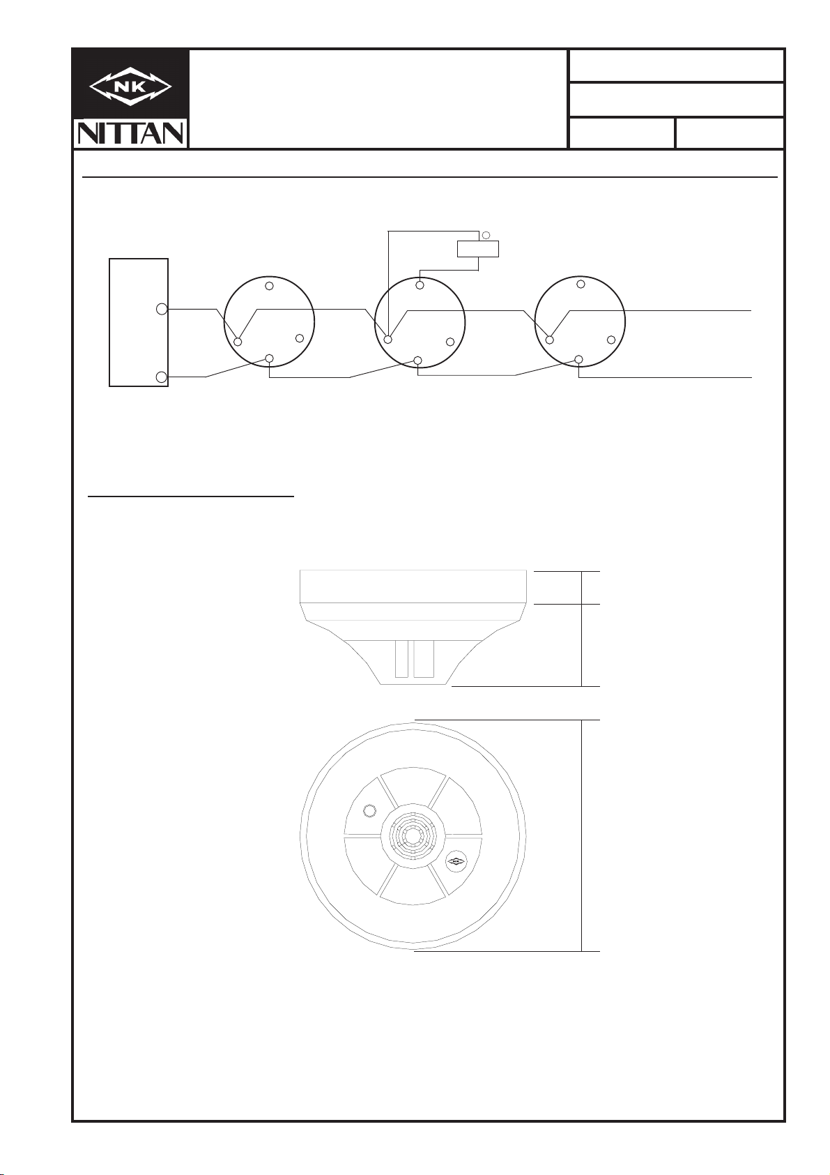
Section 9 - CONNECTIONS (Also suitable for ST-I/ST-P-AS smoke sensors)
Section 10 - DIMENSIONS
STB-4base
_65
33
65
6
3
5
11
STB-4base
LED
1
+
STB-4base
+
SIG+
S-
Low current LED 3mA max.
(STA-R1).
loopreturnto
controlpanel
15mm
49mm
104mm
www.acornfiresecurity.com
www.acornfiresecurity.com

Other Nittan Accessories manuals


