5
Inner width of sash - 150
●Cut the rail to the inner width of the sash less
150mm.
●Cut off the correct end according to the
instructions given on the sticker as follows:
• For the right-handed opening type, cut off
the right end as viewed from the front.
• For the left-handed opening type, cut of the
left end as viewed from the front.
● If the distance between the cutting face of the
rail and the reference mounting hole is no
less than 80mm, make a new hole φ5.5mm
for installing the rail at the position 50mm
from the end.
50
If no less than 80mm, make a new hole.
32.5
●Insert 2 plate nuts in the T groove in the rail.
●Match the plate nuts to the mounting holes in
the control rack set, then install the control
rack set with screws (M4 ×8 truss screws)
furnished with the product.
90-100mm
A+120 120 120 120
2
1
32
22
3 4 5
矢印方向を扉の
中心に向けて
取
り付けて下さい
ハンガーA
中
心
125
Pitch of 300 A
10
125
ハンガーB
心
中中心に向
けて
取
矢印方向を
扉の
り付
けて
下
さい
6
6
り付けて
下
さい
中心
に
向
け
て
取
矢印方向を扉の
ハンガーA
SC−C03
心
中
L/
NXX
XXX
●In assembling and reengaging the clutch gears, follow the
"Procedure for assembling and reengaging clutch gears."
●Install the control device on the hanger on the door front end with
screws (M5 ×12 pan head screws) furnished with the product.
Install it with the door open by at least 60cm (where it does not
engage with the control rack set).
7
8
注意
故障の原因と
なりますの
で調整は下記の範囲内で
行
って下さい
。
強方向:
5
回転以下
弱方向:
2
回転以下
弱
PS−03R
LOTNO.
04223
強
行って下
さい。
故障の原因となりま
す
の
で調整は下記の範囲内
で
強方向
:5回転以下
弱方向
:2回転以下
注意
PS−03R
強
LOTNO.
04308
弱
矢印方向を扉の
中心に向けて取
り付けて下さい
ハンガーA
中
心
SC−C03
L/NXXXXX
●Temporarily tighten the screws
(M4 ×5 pan head screws) fur-
nished with the product, on the
fittings for installing the pull
spring. Then insert them into the
T groove in the bottom of the rail.
●Tighten the screws to fix the
fittings. Install the pull spring on
the fittings for installing the pull
spring, with screws (M3 ×8 pan
head screws) furnished with the
product.
●Install the stop roller on the hanger on the door
front end with screws (M5 ×8 pan head screws)
furnished with the product.
●Insert the plate nuts in the T groove in the rail,
then install the plate spring with screws (M4 ×8
truss screws) furnished with the product.
9
り付けて下さい
ハンガーA
矢印方向を扉の
中心に向け
て取 中
心
SC−C03
L/NXX
XXX
L/N 04126
中心に向けて取
り付けて下さい 心
矢印方向を扉の
ハンガーA
中
SC−C08
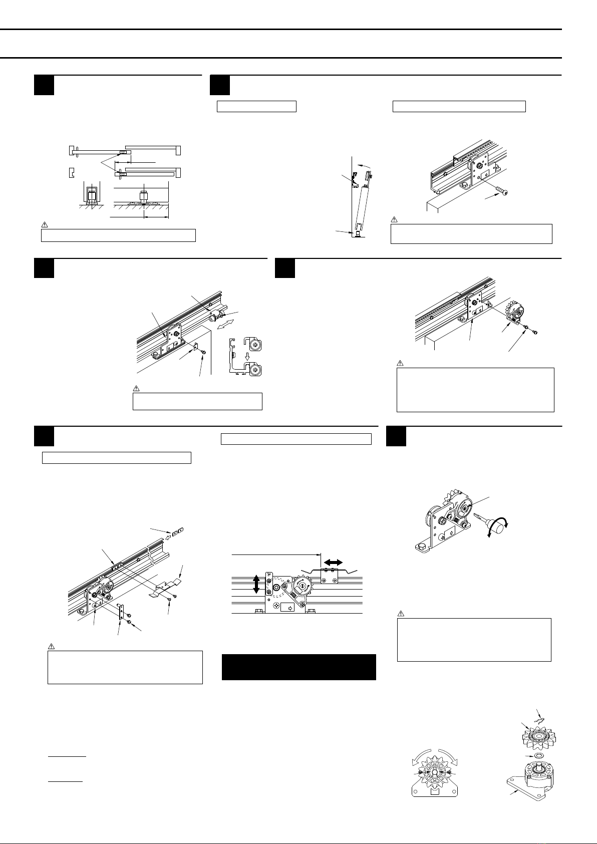
●If the closing force needs
adjustment, turn the gear shaft
with a screwdriver for
adjustment.
Label on the component
Turn it in the direction of
"Strong" →to increase the
closing force.
Turn it in the direction of "Weak"
→to decrease the closing force.
●Turn the speed
adjusting screw of
the control device
with a screwdriver
to adjust the
closing speed. (It is
factory-configured
to the highest
speed.)
●Slide the control rack set to adjust the controlling
interval, thus adjusting the closing speed.
• Shorten the controlling interval →to increase
the closing speed.
• Elongate the controlling interval →to decrease
the closing speed.
10
04223
弱方向:2
回転以下
強方向:5
回転以下
行って下さい。
故障の原因と
なり
ま
す
の
で調整は下記の範囲内
で
注意
強
弱
PS−03R
LOTNO.
ハンガーA
り付け
て下さい
中心に向けて取
矢印方向を扉の 中
心
SC−C03
L/NXX
XXX
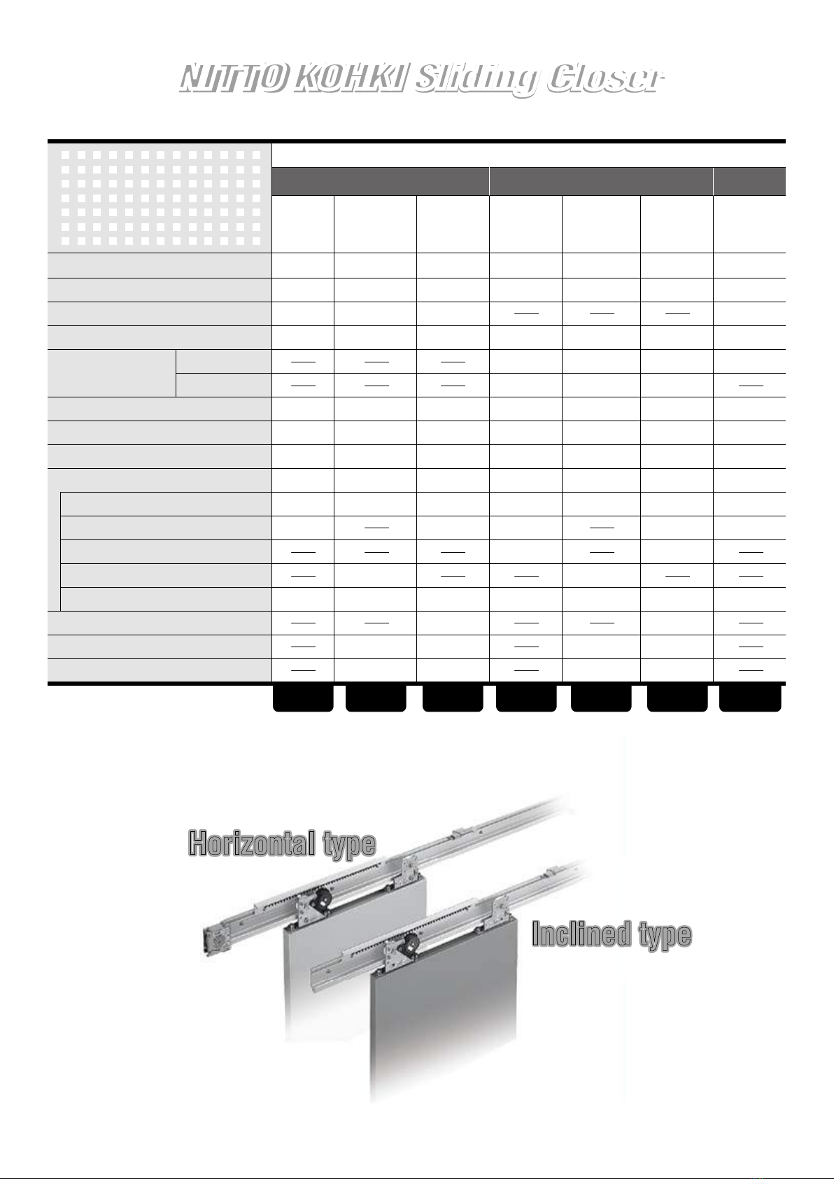
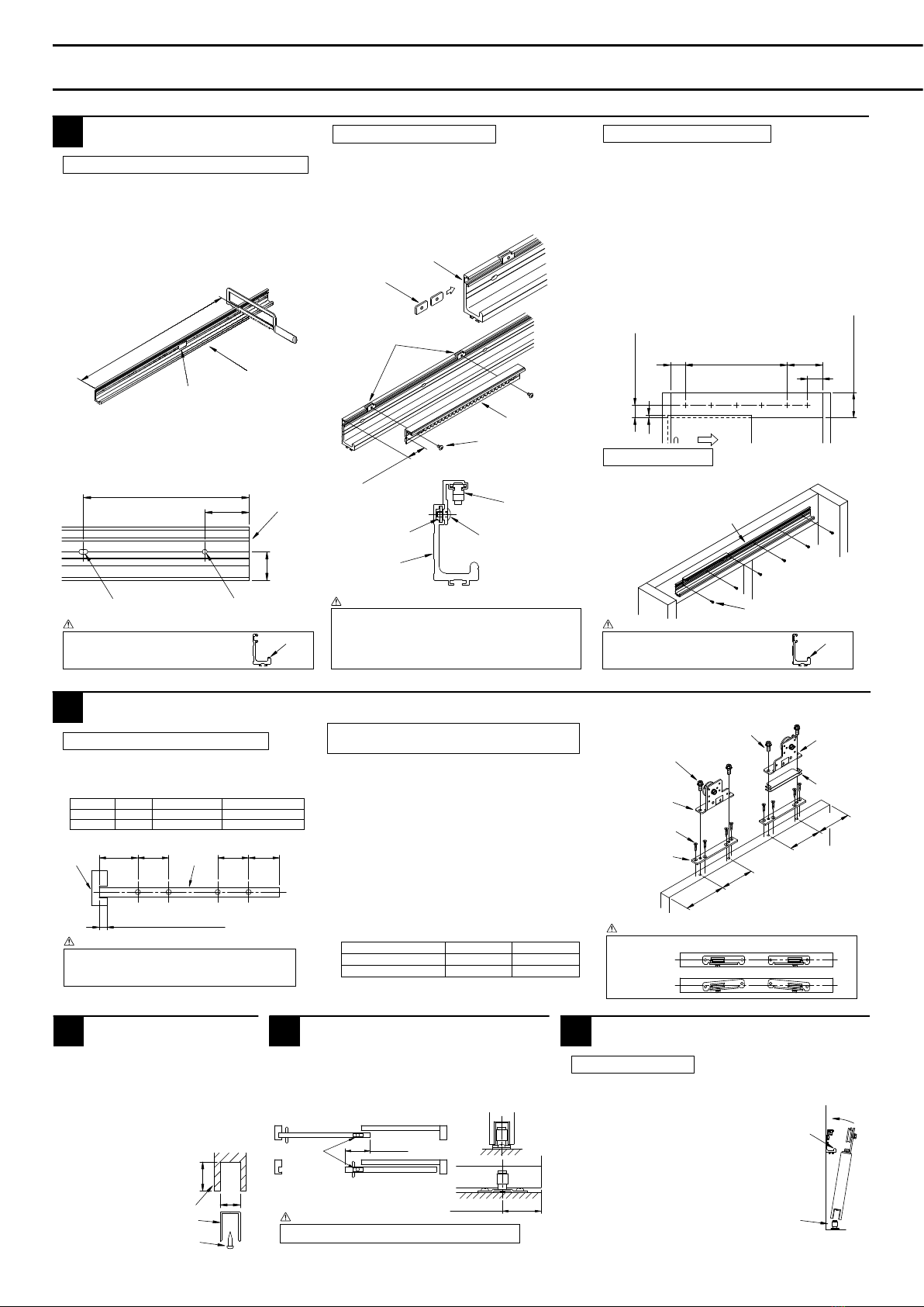
Installation Procedure for
NSC-CW
For wooden fittings, horizontal
Installation Procedure for
NSC-CW
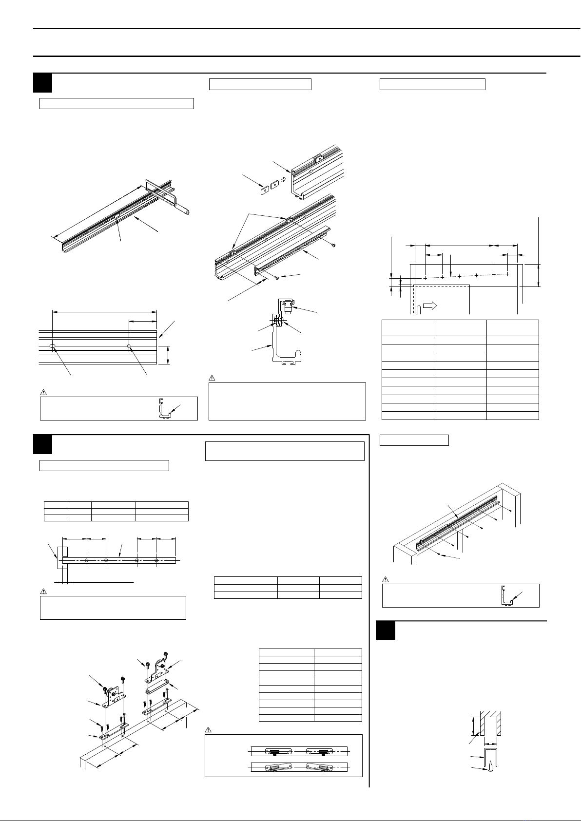
1) Cutting the rail, making a new mounting hole
2) Installing a control rack set
Installing a rail
Sticker
Front
Cutting face of rail
R groove
Reference mounting hole Make a new hole φ5.5mm
T groove of rail
Plate nut
Plate nut
Plate nut
Control rack set
Control rack set
M4 ×8 truss screw
M4 ×8 truss screw
Rail
●When making any change in the rail,
take care not to scratch the runway.
Caution
Cautions
Runway ●Install the rail horizontally.
●When installing the rail, take care not
to scratch the runway.
Caution Runway
●Be sure to use specified screws furnished with the
product. Using any unspecified screw may cause it to
interfere with the clutch gear of the control device
●Tighten the screws securely. Otherwise an abnormal
noise or imperfect control may result.
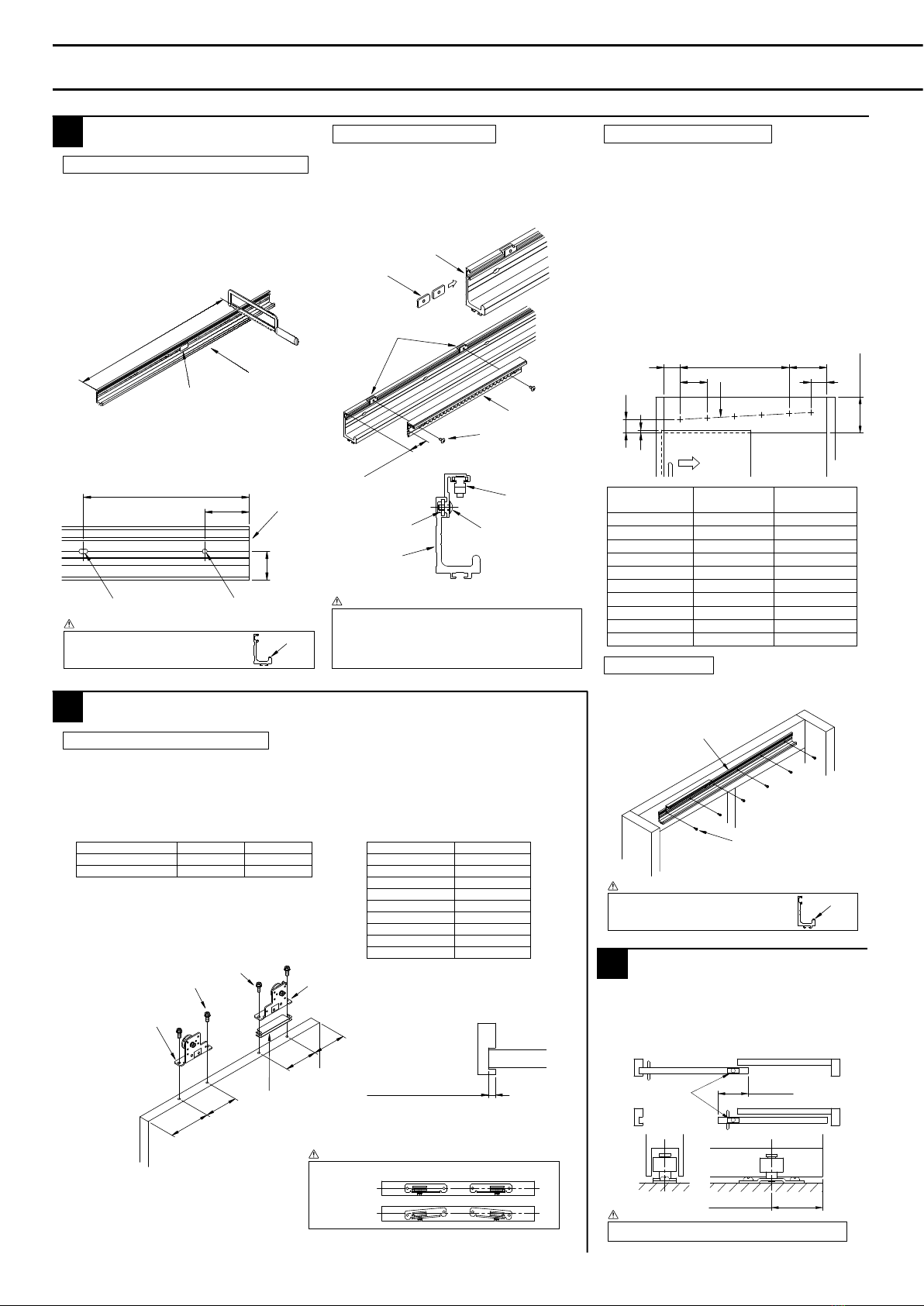
●Tap holes (M5, pitch 0.8) horizontally at
intervals of 300 with the hole specified below
as the reference point.
• Dimension from the inside of the sash on
the door front end = 125mm
• Dimension from the bottom of the top frame
of the sash = 65mm (CW23)
= 70mm (CW36/CW48)
(When the cover between the top frame and
door is 10mm)
●If the dimension A in the diagram below (the
dimension from the final hole at a pitch of 300
to the inside of the sash on the door back
end) is no less than 155mm, tap a hole at
125mm from the inside of the sash.
3) Setting rail mounting holes
●Install the rail with screws (φ5mm ×30 truss
tapping screws or M5 ×16 pan
head screws) furnished
with the product.
4) Installing the rail
65 (CW23)
70 (CW36/CW48)
No less than 125 (CW23)
No less than 130 (CW36/CW48)
Door front end
Right-handed
opening
Door back end
Rail
φ5mm ×30 truss tapping
screws or M5 ×16 pan
head screws
●For the bottom diameter of the coach screws, be
sure to follow the specified dimension. If the bottom
hole diameter is too large, the door may come off.
Caution
●Make holes in the top of the door at the
positions shown in the diagram below, as
specified below.
1) Making holes in the top of the door
Installing the hanger
Model
CW23
CW36/48 φ5.5-6
φ9Coach screw
Wooden door plate
Hole Remark
●As shown in the diagram, install the wooden
door plate with screws (φ5mm ×30 pan head
tapping screws) furnished with the product,
with the M8 screw as the reference point.
(The wooden door plate is installed on the
CW36/48 only.)
●As shown in the diagram, install the hanger A,
hanger B, and height adjusting plate.
●Install the hanger while orienting it as shown
in the table below, according to the
instructions given on the sticker attached to
the hanger.
2) Installing the wooden door plate, and the
hanger
Right-handed opening type
Left-handed opening type
Hanger A side
Door front end Door back end
Hanger B side Hanger B side
Hanger A side
A
+120 120 120 120
φ8×50 Coach screw (CW03)
M8 ×30 Hexagon head bolt (CW08)
φ8×50 Coach screw (CW03)
M8 ×25 Hexagon head bolt (CW08)
Hanger A
for right-handed door
front end
for left-handed door back
end
φ5×30
Countersunk head tapping
screw
(CW36/48 only)
Wooden door plate
(CW36/48 only)
Door front end
Door
back end
Hanger B
for right-handed
door front end
for left-handed
door back end
Height
adjusting plate
●Install the hanger on the centerline of the door.
Caution
Good
No good
●Cut off the guide rail according to
the door width.
●Carve the door bottom to the
dimension shown in the
dimension specified below, then
install the guide rail with screws
(φ4mm ×16 pan head tapping
screws) furnished with the
product.
Installing the guide rail
Door bottom
Guide rail
φ4mm ×16 pan head
tapping screws
●Install them in the middle of the door lap.
(The product does not come with such
mounting screws.)
●Install them so that the door become vertical
with the floor area.)
Installing the guide rollers
●Be sure to use the guide rollers.
Caution
Guide rollers
Lap
Lap/2
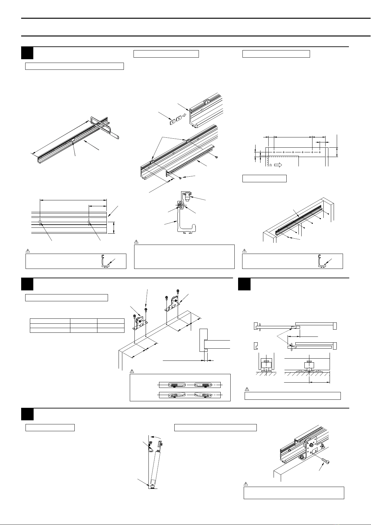
5
●Before mounting the door, wipe off the dirt
from the rail runway.
●Match the door bottom to the
guide rollers, then suspend the
door rollers and mount them
onto the rail runway.
●Check that the door operates smoothly.
●Adjust the clearance between the door
and jamb by changing the number of
height adjusting plates (optional).
1) Mounting the door
Mounting the door
Guide rollers
Runway
●Tighten the
door-retaining
screws (M8 ×30 pan
head screws) in the
hangers A and B.
2) Installing the door-retaining screws
●Tighten the screws securely to prevent the door from
coming off.
Caution Door-retaining screw
(M8 ×30 pan head screw)
●Install the door stopper bearing plate on the
hanger on the door back end with screws
(M5 ×8 pan head screws) furnished with the
product.
●Insert the door stopper fittings in the rail
runway. Slide the door stopper fittings, adjust
the door-opening position, then tighten the 2
fixing screws and fix the fittings.
Installing the door stopper
Hanger at door
back end
Door stopper fitting
Fixing screw
Door stopper
bearing plate
M5 ×8 pan head screw
●Tighten the fixing screws securely, or the door
stopper fittings may become out of place.
Caution
Installing the control device
Hanger on
door front end
Control device
M5 ×12 pan head screw
●Check the orientation of the control device
(right- or left-handed). Be sure to orient it
correctly, or the control will not work.
●Be sure to install the control device after
mounting the door. When suspending and
mounting it, the door may strike and
damage the rail or other component.
Caution
1) Installing the stop roller and plate spring
●Adjust the position of the plate spring to stop it at
the position where the door is fully open.
●Move the stop roller up and down to adjust the
stopping force.
•
Increase the stopping force. Raise the stop roller.
•
Reduce the stopping force. Lower the stop roller.
2) Adjusting the stopping position and force
Installing the stop device
Adjusting the closing force and closing speed
Installing a pull spring
1) Installing a pull spring 1) Adjusting the closing force
●Draw the wire of the pull spring,
then hook it on the hanger on
the door
front end.
2) Setting the wire
M4 ×5 pan
head screw M3 ×8 pan
head screw
Pull spring
Fitting for installing
the pull spring
T groove in the rail
●Do not draw the wire with the pull spring
alone (before the installation).
Any such practice might scratch the wire.
Caution
●Be sure to use the specified screws furnished with the product.
Using any unspecified screw may cause it to interfere with
another component.
●Securely tighten the screws furnished with the product, to keep
the stop roller and plate spring in place at all times.
Caution
Effective opening + 160 - cut-in
at door front end
(distance from rail tip at door front end)
Plate nut
Plate nut
Plate spring
Hanger on door front end M4 ×8 truss screw
M5 ×8 pan head screw
Stop roller
2) Adjusting the closing speed
●Turn the speed adjusting screw lightly. Otherwise an
imperfect control may result. After turning it all the way home,
do not turn it with overstrain.
●A change in the ambient temperature varies the closing speed
somewhat. As the temperature rises, the speed increases. As
the temperature declines, the speed decreases.
Caution
●Overwinding it in the direction of "Strong" will cause a
breakdown. Be sure to set it to a value not exceeding the
number of windings indicated on the label on the component.
Caution
Speed adjusting screw
Becomes slower
(direction S)
Becomes faster
(direction F)
R
The control device used for this product is for both orientations (right- and left-handed). The orientation of the clutch gear determines whether it is right- or left-handed.
When assembling and reengaging the clutch gear, follow the procedure described below.
1. Procedure for assembling the clutch gear
• Insert the washer into the shaft of the control device.
• Insert the clutch gear into the shaft.
If right-handed
Make the white surface (the R-stamped surface) at the center of the clutch
gear face upwards, then insert it while turning it in the direction of the arrow
for the right-handed opening type illustrated in the right-hand diagram.
If left-handed
Make the blue surface (the L-stamped surface) at the center of the clutch
gear face upwards, then insert it while turning it in the direction of the arrow
for the left-handed opening type illustrated in the right-hand diagram.
• Install the snap retainer in the groove at the tip of the shaft.
2. Procedure for reengaging the
clutch gear
• Remove the clutch gear in reverse order
of assembly. (Remove the clutch gear
while turning it in the same direction as
in assembly.)
• Assemble the clutch gear according to
the assembly procedure.
• The product comes with one spare snap
retainer.
Procedure for assembling and reengaging the clutch gear
Direction of rotation
for assembly
for left-handed (for L)
Direction of rotation
for assembly
for right-handed (for R)
Blue surface
at the center
for left-handed
(for L)
White surface
at the center
for right-handed
(for R)
Snap retainer
Clutch gear
Washer
Control device
Jamb Door top
Door front end Door back end
A (cut-in at door front end)
(The diagrams shown represent a right-handed opening type. The left-handed
opening type is symmetrical with the type represented in these diagrams.)
35mm and over
20mm and over
Depth
When the clutch gear is inserted or removed,
be sure to turn it as following instruction.