DEUTSCHTEC TL240 User manual

Installation manual
Deutschtec GmbH
Am Fuchsbau 13
15345 Petershagen/
Eggersdorf Deutschland
Phone: +49 (0)3341 30 22 4 - 0
Fax: +49 (0)3341 30 22 4 - 25
www.deutschtec.de
Telescopic
TL240 & TL240ES

Contents
1EN.09.09052022 2EN.09.09052022
Introduction 3
Symbols of the manual 3
1. General Information of the Product 4
1.1 Product Introduction 4
1.2 Technical Specications 5
1.3 Copyright 6
1.4 Standards 6
1.5 Warranty Guidelines 6
1.6 Declaration of Incorporation 7
1.7 Certication 8
1.8 Signage 9
2. Contents of Delivery 10
3. Assembly and Installation 14
3.1 Precautionary Measures 14
3.2 Required Tools 15
3.3. Technical drawings 16
3.3.1 Two-leaves door version(TBS) 16
3.3.2 One-leaf door version(TBS) 17
3.4 Part´s Position 17
3.5. Installation Steps 20
3.5.1 Check leaves & opening dimensions 20
3.5.2 Mark the right position 21
3.5.3 Fix the rail to the lintel 21
3.5.4 Possible screw grooves 22
3.5.5 Mount the stoppers at the end points 22
3.5.6 Mount the TL hanger right 23
3.5.7 Mount the TL hanger left 24
3.5.8 Install the side leaves/leaf 24
3.5.9 Mount the inner leaves/leaf 26
3.5.10 Align the inner leaf with the short hanger(s) 26
3.5.11 Align the inner leaf with the long hanger(s) 27
3.5.12 Position of hangers after adjustment 27
3.5.13 Slide both inner leaves/leaf to be able to install the oor guide(s) 28
3.5.14 Install inner oor guide 28
3.5.15 lift and slide the inner leaves/leaf to the oor guide(s) 29
3.5.16 Align the inner leaves/leaf with the xed leaves/leaf and accordingly adjust the stopper 30
3.5.17 Mount the xed TL timing belt base plate 30
3.5.18 Align inner leaves/leaf with xed TL timing belt base plate 31
3.5.19 Tensioning timing belt by side screw 32
3.5.20 Mount TL timing belts 32
3.5.21 Clamp TL timing belt(s) 33
3.5.22 Check for equal distances 34
3.5.23 Mount the SLH rail 35
3.5.24 Mount the SLH stoppers 35
3.5.25 Mount SLH hangers 36
3.5.26 Mount the outer leaves/leaf 37
3.5.27 Install outer oor guide 37
3.5.28 Lift and slide the outer leaves/leaf 38
3.5.29 Connect the inner leaves/leaf with outer leaves/leaf 39
3.5.30 Connect TL rail to SLH rail with joiners 39
3.5.31 Passing at nuts for xing operator components 40
3.5.32 Components installation as illustrated 40
3.5.33 Timing belt installation over pulleys and xing on belt clamps (2) 41
3.5.34 Operator Cover 42
3.5.35 Side Covers 42
3.6 Starting the Operator 43
3.6.1 Standard Version 43
3.6.2 Escape Version 43
3.7 Modifying the Parameters 53
3.8 Sensors Setup Table 54
3.9 Wiring Diagrams 55
3.9.1 Wiring Diagram Optex OA-Flex Sensor 55
3.9.2 Wiring Diagram BEA ZEN/ZENSAFE Sensor 56
3.9.3Wiring Diagram BEA ZEN/ZENSAFE Sensor 57
3.9.4 Wiring Diagram BEA IXIO-DT3 Sensor 58
3.9.5 Wiring Diagram BEA VIO Sensor 59
3.10 Block Diagram 60
3.11 Mechanical Key Switch 61
4. Maintenance Service 62
4.1 Precautionary Measures 62
4.2 Maintenance Check 62
4.3 Timing Belt Tension 64
4.3 Mechanical Faults 64
4.5 Troubleshooting 65
4.5.2 LED Status – Error Codes 67
5. User Instructions 69
5.1 Precautionary measures 69
5.2 Main Elements of the system 70
5.3 Digital key switch 73
5.3.1 Operating the system with the digital key switch 73
5.3.2 Main menu 74
5.4 System behavior 75
5.4.1 Closing cycle 75
5.5 Failures 76
5.6 Error handling 77
5.6.1 Handling errors by mechanical key switch 77
5.6.2 Handling errors by digital key switch 77
5.7 Mandatory Routine Maintenance 77
5.8 Cleaning 78
6. Disabling and Dismantling 79

3
This guide is for service engineers who service Tl240 and TL240ES and SLH240ES operators and gives
information on:
- System specifications
- Maintenance
Introduction
- Assembly, installation and settings
In this booklet, the installation process is predesignated for the engineers who install service Tl240 and
TL240ES operators.
- User guidance
Symbols of the manual
This manual uses the following symbols and the keywords indicate hazards that pose a risk to life and limb:
NOTICE: An important hint.
INFORMATION: An important information.
DANGER: A hint representing a danger that immediately leads to death or
severe injury.
WARNING: A hint representing a danger that can lead to death or severe
injury.
EN.09.09052022
DANGER
WARNING
4
Due to these models' smart design to be energy-saving and immune to wear, we have been able to present
you an entry solution which is long-lasting, environment-friendly and an excellent value for your money. What
is more, they have all successfully passed one-million-cycle test and are TÜV approved.
1.1 Product Introduction
1 General Information of the Product
TL series' telescopic mechanism is designed and made in a way that can easily give a brilliant performance in
places with high traffic. Having passed one-million-cycle test, this mechanism is also considered absolutely
suitable for escape doors.
TL240ES secure entry solutions are specially designed and produced for escape routes and emergency exits
but can also be applied in normal entrances.
EN.09.09052022

6
1.3 Copyright
This manual was prepared and issued by Deutschtec GmbH. All rights are reserved. The information in this
manual is the property of Deutschtec GmbH; located in Germany. Disclosure of this information or any part of
it to third parties is not permitted, except with prior and explicit written permission of Deutschtec GmbH.
Deutschtec GmbH has the reserved rights to improve its products without notice. Therefore, it is possible that
the installed products show some differences from the description in this manual. This manual is based on the
standard product.
- EN 60335
These operators in agreement with following standards:
- EN 16005
- EN ISO 13849
- EU low voltage directives
1.5 Warranty Guidelines
Conformance with the following installation and service procedures must be maintained to assure a proper
installation and to maintain the Deutschtec warranty.
- EU EMC directives
- DIN 18650
1.4 Standards
Not following installation manual may result in faulty operation, injuries and
voiding warranty.
EN.09.09052022
Specification
Specification Specification
5EN.09.09052022
1.2 Technical Specification
Tl240
Tl240 Tl240
TL240ES
TL240ES TL240ES
Opening width - single panel
Opening width - double panel
Operator height
Operator depth
Opening speed
Closing speed
Hold-open time
Ambient temperature
Type of Protection
Track prole
Anti-noise rubber prole
Power supply
Power Consumption max. 250 W max. 250 W
Gear motor power
226 mm
155 mm
anti-crash
Stainless Steel/Aluminum
1800 - 4000 mm
900 - 3000 mm
0 - 30 s
IP 20
100 W
Variable up to 1.1m/s
(Four leaves )
Variable up to 1.1m/s
(Four leaves)
Variable up to 1.1m/s
(Four leaves )
Variable up to 1.1m/s
(Four leaves)
226 mm
155 mm
anti-crash
Stainless Steel/Aluminum
1800 - 4000 mm
900 - 3000 mm
0 - 30 s
IP 20
100 W
Emergency exit routes in both directions
Mechanical key switch (Optional)
24V DC output for external accessories
Emergency exit routes in
both directions
Possibility of using more
software and hardware
options by using DMS
device
Mechanical key switch
(optional)
24V DC output for external
accessories
Power Lock
Possibility of using
electromechanical lock
(optional)
Possibility to use safety
sensors with testing signal
Programmable relay output
(optional)
Max operation cycles with 2.2 Ah
battery (Optional)
Max operation cycles with 7.2 Ah
battery (Optional)
Possibility to adjust force limitation
according to DIN18650 and EN16005
400
1000
-
Read-out error memory
with error codes (with digital
programmable switch)
Programmable relay input
(optional)
-
-
-
-
-15 to + 50 C -15 to + 50 C
230V/33V,50VA (Peak 120VA) 230V/33V,50VA (Peak 120VA)
Max leaf weight, double:
2 x 150 Kg
2 x 150 Kg
Max leaf weight, four
4 x 100 Kg
4 x 100 Kg

8
1.7 Certification
EN.09.09052022
7
1.6 Declaration of Incorporation
EN.09.09052022
Declaraon of Incorporaon
In accordance with Annex II section 1.B. of the EC Machinery Directive 2006/42/EG
Authors and persons responsible for creating the relevant technical documents:
Deutschtec GmbH
Am
Fuchsbau
13
15345Petershagen/Eggersdorf
Germany
We hereby declare that the incomplete machine:
Telescopic Door Operator Type: TL240 and TL240 ES
as long
as
supply
is
possible
within
the
scope
of
delivery,
and
corresponds
to
the basic
requirements
of
the
following
directives
(refer
to
the
Annex
regarding
which
requirements were
met):
Machinery Direcve 2006/42/EG
EU Official Journal L 157/24 dated 09.06.2006
EG Low Voltage Direcve2006/95/EG
EU Official Journal L 374/10 dated 27.12.2006
EMC Direcve 2004/108/EG EU Official Journal L 390/24 dated 31.12.2004
Harmonized standards that were used, whose references have been published in
the Official Journal of the EU:
EN ISO 13849-1: 2016-6
EN 60335-1:2012
EN 16005:2012
Petershagen/Eggersdorf, 17.01.2021 (Place, Date)
Requirements of Annex I of 2006/42 EC, which have been complied with. The
numbers refer to the sections of Annex:
I: 1.1.5, 1.3.4, 1.3.7, 1.5.14, 1.3.1, 1.3.2, 3.4.5, 1.2.1, 1.3.8.2, 1.4.1, 1.4.3, 1.5.1,
1.5.2, 1.5.5, 1.5.6, 1.5.7, 1.5.8, 1.5.9, 1.5.10, 1.5.13, 1.1.3, 1.1.6, 1.2.6, 1.6.3,
1.5.15, 1.3.2, 1.3.3, 1.6.1, 1.2.4.1, 1.2.4.3, 1.2.4.4, 1.2.3, (partially)
10
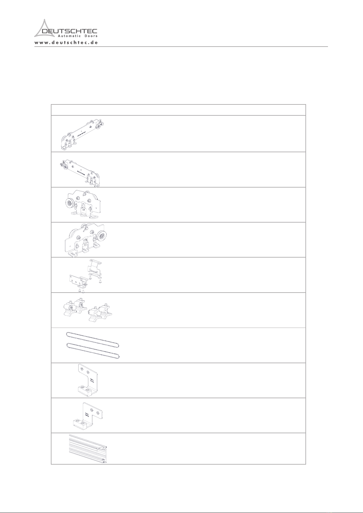
2. Contents of Delivery
For TL240 and TL240ES series:
EN.09.09052022
9
1.8 Signage
Clear signage on automatic doors is a key component of the safety system. Deutschtec has prepared several
warning signs (in accordance with ISO 7010:2020) that must be attached to the relevant parts of this product.
Signage are defined below:
Signage Interpretation Location to be attached on
This warning sign is used to show
the risk of electric shock advising to
avoid touching the component.
This warning sign shows the risk of
hand injury with moving parts.
This opaque decal inform s
pedestrians about the presence of
the transparent glazing.
This decal might be presented with
different designs.
This pictogram is mandatory for
doors with an emergency break-out
function.
This signage should be attached on
the power supply.
This signage should be attached on
the hangers inside the operator.
This opaque decal should be
placed at 1270mm ± 305mm
from the floor to the centerline of
the sign visible from both sides of
each fixed leaves.
This signage should be placed at
1270mm ± 305mm from the floor
to the centerline of the sign visible
from the opening side of the door.
Risk of Electric Shock
Risk of Crushing Hands
In Emergency Push to Open
EN.09.09052022
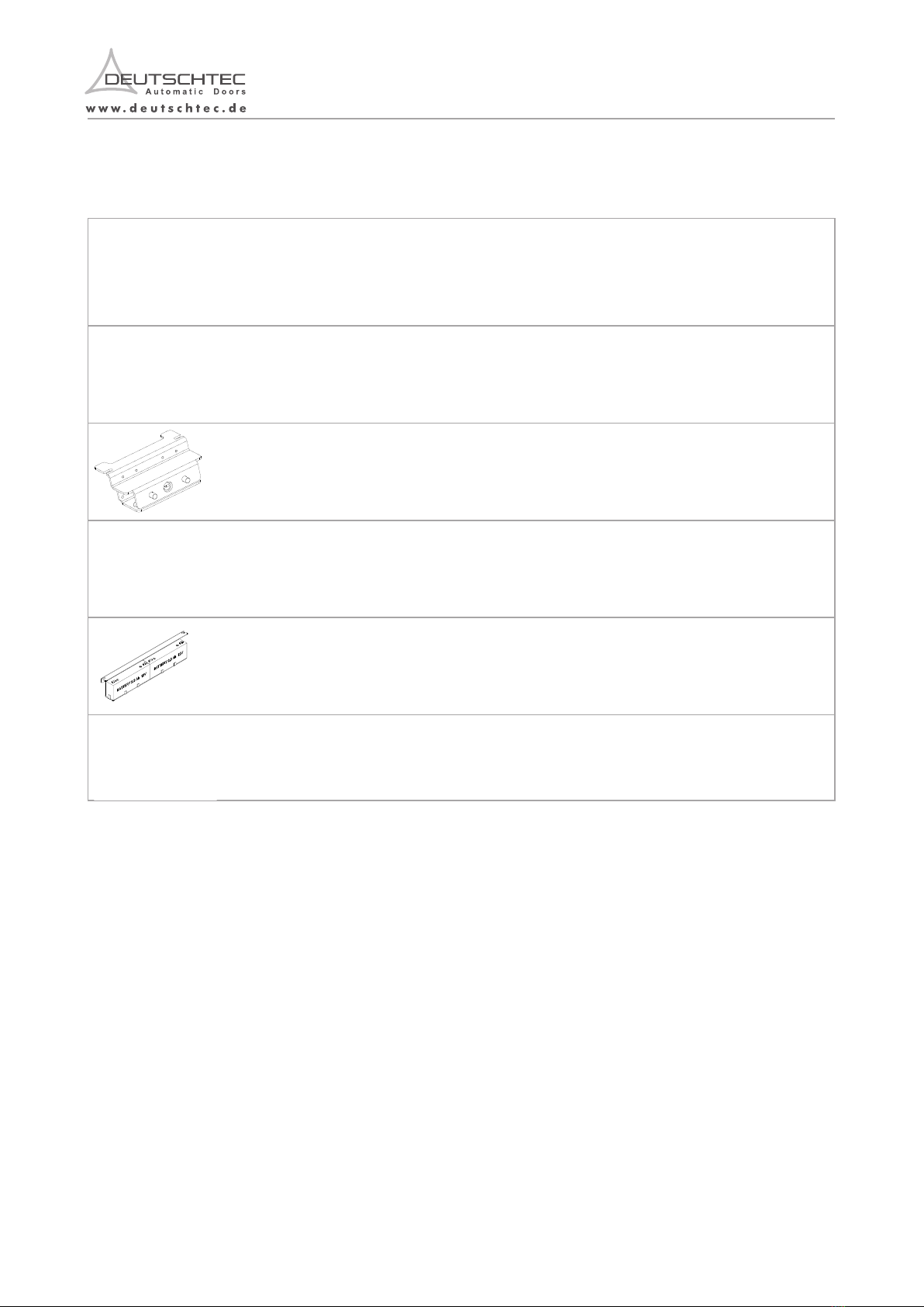
Art.-No. Description This kit/set incl.
1000000231 TL Hanger Long Left
10000000235
1000000214
1000000229
1 Pcs.
1 Pcs.
1 Pcs.
1000000237 Belt Clamp Set
1000000108 SLH Stopper Set
1 Pcs.
1 Pcs..
1000000244 TL Timing Belt HTD 5M
6mm, 6 meter
1 Pcs.
1 Pcs.
TL Hanger Long Right
TL Hanger Short Left
TL Hanger Short Right
1000001694
2 Pcs.
1000001695
Complete Floor Guide Left
Complete Floor Guide Right
2 Pcs.
1000000036 Tl240 Telescopic Profile Set, SS
4m
1 Pcs.
10
2. Contents of Delivery
For TL240 and TL240ES series:
EN.09.09052022
9
1.8 Signage
Clear signage on automatic doors is a key component of the safety system. Deutschtec has prepared several
warning signs (in accordance with ISO 7010:2020) that must be attached to the relevant parts of this product.
Signage are defined below:
Signage Interpretation Location to be attached on
This warning sign is used to show
the risk of electric shock advising to
avoid touching the component.
This warning sign shows the risk of
hand injury with moving parts.
This opaque decal i n f o rms
pedestrians about the presence of
the transparent glazing.
This decal might be presented with
different designs.
This pictogram is mandatory for
doors with an emergency break-out
function.
This signage should be attached on
the power supply.
This signage should be attached on
the hangers inside the operator.
This opaque decal should be
placed at 1270mm ± 305mm
from the floor to the centerline of
the sign visible from both sides of
each fixed leaves.
This signage should be placed at
1270mm ± 305mm from the floor
to the centerline of the sign visible
from the opening side of the door.
Risk of Electric Shock
Risk of Crushing Hands
In Emergency Push to Open
EN.09.09052022
Art.-No. Description This kit/set incl.
1000000231 TL Hanger Long Left
10000000235
1000000214
1000000229
1 Pcs.
1 Pcs.
1 Pcs.
1000000237 Belt Clamp Set
1000000108 SLH Stopper Set
1 Pcs.
1 Pcs..
1000000244 TL Timing Belt HTD 5M
6mm, 6 meter
1 Pcs.
1 Pcs.
TL Hanger Long Right
TL Hanger Short Left
TL Hanger Short Right
1000001694
2 Pcs.
1000001695
Complete Floor Guide Left
Complete Floor Guide Right
2 Pcs.
1000000036 Tl240 Telescopic Profile Set, SS
4m
1 Pcs.
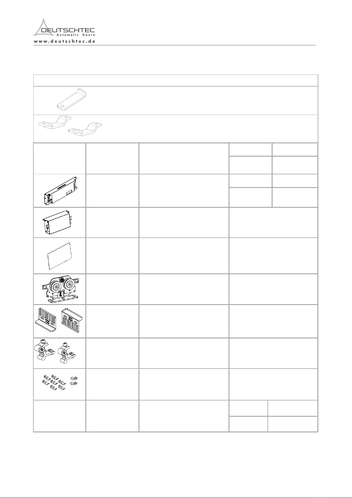
12 EN.09.09052022
11
EN.09.09052022
1000000247
1000000230
1 Pcs.
2 Pcs.
TL Rail Joiner Middle
TL Rail Side Joiner
Art.-No. Art.-No.Description Description
This kit/set incl. This kit/set incl.
1000000131
SLH
Pack
Screw
1Pcs
1000000636
SLH -240ES Data
Connection
Cable
and
26
Pin
Connector
1PCS TL240ES
1000000038
SLH Assembled Motor
100W-
24V
1PCS TL240
2 PCS TL240ES
1000000057
SLH/PR Control Unit -Steel Case
1 PCS TL240
2 PCS TL240ES
1000000076
SLH/ PR Power Pack Steel
Case 1 Pcs.
Side Cover Pack 1 PCS
SLH Hanger & Roller 4 Pcs.
SLH Belt Clamp Set 1
Pcs
SLH Stopper Pack 1
Pcs
SLH Cover and Cable Clip
1
Pcs
SLH/Prime Standard Cable Pack 1PCS TL240
2 PCS TL240ES
1000000081
1000000094
1000000108
1000000115
1000000119
1000000333
SLH
240
ES -
Power
Connection
Cable
and
4
Pin
Connectors
1PCS TL240ES
1000000124
Battery
Pack
-
GN 1PCS TL240ES
1000000116
GN
Cable
Clip
6
Pcs
1000000100
SLH
Idler
Pully
1Pcs
4 m SLH Rail Prole, AL
4 m SLH Cover Prole, AL
4 m General Track Prole, SS
4 m General Track Prole, AL
General Rubber Prole, for SS
General Rubber Prole, for AL
4 m SLH-Back Prole
1000000002 1 Pcs.
1000000003 1 Pcs.
1000000023 1 Pcs.
1000000004 1 Pcs.
1000000024 4 Meter
1000000005 4 Meter
1000000035
11
This section presents guide for engineers who assemble and install TL240 series doorsets.
3 Assembly and Installation
-Local building code requirements for automatic doors must be taken into consideration.
Not following installation manual may result in faulty operation, injuries and voiding warranty.
- All tasks of installation should be carried out by trained professionals authorized by Deutschtec. Following these
instructions avoids material damage and personal injuries. Any other person, under any circumstances, must not be
involved in the technical affairs of this product.
This section presents the precautionary measures that must be taken into account for the installation of the product.
3.1 Precautionary Measures
Special attention must be given to this section. Deutschtec GmbH shall not be liable for accidents caused by
ignorance of this part.
- There has to be secured space and enough time for installation of this product without any interruptions by unauthorized
individuals.
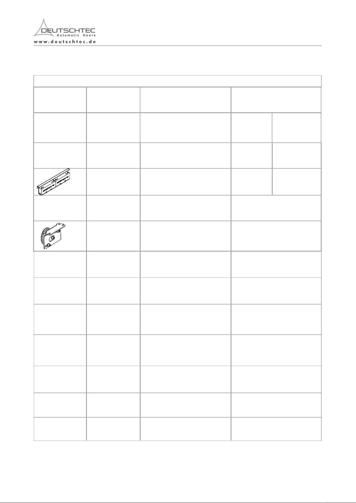
14 EN.09.09052022
Mechanical Key Switch ( Deutschtec logo)
Optional
Optional
Optional
Optional
Optional
Optional
Digital Programme Switch (Deutschtec logo)
Electromechanical Lock-GN
HSML_Complete Lock for SLH
Battery Pack - GN
Battery Set - GN
1000000147
1000000166
1000000174
1000000944
1000000124
1000000392
Description Kit/set incl.
Article NO.
- Assembly and installation of the system has to be performed by trained technicians using protective equipment, such as:
- Goggles
- The areas with a risk of injury must be visually labeled by safety barricades and signs to keep pedestrians away from
hazardous areas.
- Ensure equipment stability to prevent any unintended dangerous movement or collapse of any part of the equipment.
- While moving long components of the product, watch both sides of them.
- Ensure the stability of the installed operator parts on the wall. Secure the parts against falling.
- Do not install the drive on a wall that is damp or may get wet.
- Ensure the installation area is safe for workers, technicians and pedestrians.
- Gloves
- Safety footwear
- Hard hats
- Make sure the floor is not slippery.
- Make sure the workspace is well-lit.
- Never perform the high risk tasks alone.
- Pay attention to the hazard signage attached to the components inside the operator.
- Before lifting heavy modules identify the center of gravity of the object and beware to control the object movements.
Before working with electrical system, make sure the drive is disconnected from the power supply.
signage and pictograms to the locations specified in section 1.8.
Various screws and dowels are required for fastening. These are dependent on the sub foundation.
Note: Consumables
DANGER
13
This section presents guide for engineers who assemble and install TL240 series doorsets.
3 Assembly and Installation
-Local building code requirements for automatic doors must be taken into consideration.
Not following installation manual may result in faulty operation, injuries and voiding warranty.
- All tasks of installation should be carried out by trained professionals authorized by Deutschtec. Following these
instructions avoids material damage and personal injuries. Any other person, under any circumstances, must not be
involved in the technical affairs of this product.
This section presents the precautionary measures that must be taken into account for the installation of the product.
3.1 Precautionary Measures
Special attention must be given to this section. Deutschtec GmbH shall not be liable for accidents caused by
ignorance of this part.
- There has to be secured space and enough time for installation of this product without any interruptions by unauthorized
individuals.
14 EN.09.09052022
Mechanical Key Switch ( Deutschtec logo)
Optional
Optional
Optional
Optional
Optional
Optional
Digital Programme Switch (Deutschtec logo)
Electromechanical Lock-GN
HSML_Complete Lock for SLH
Battery Pack - GN
Battery Set - GN
1000000147
1000000166
1000000174
1000000944
1000000124
1000000392
Description Kit/set incl.
Article NO.
- Assembly and installation of the system has to be performed by trained technicians using protective equipment, such as:
- Goggles
- The areas with a risk of injury must be visually labeled by safety barricades and signs to keep pedestrians away from
hazardous areas.
- Ensure equipment stability to prevent any unintended dangerous movement or collapse of any part of the equipment.
- While moving long components of the product, watch both sides of them.
- Ensure the stability of the installed operator parts on the wall. Secure the parts against falling.
- Do not install the drive on a wall that is damp or may get wet.
- Ensure the installation area is safe for workers, technicians and pedestrians.
- Gloves
- Safety footwear
- Hard hats
- Make sure the floor is not slippery.
- Make sure the workspace is well-lit.
- Never perform the high risk tasks alone.
- Pay attention to the hazard signage attached to the components inside the operator.
- Before lifting heavy modules identify the center of gravity of the object and beware to control the object movements.
Before working with electrical system, make sure the drive is disconnected from the power supply.
signage and pictograms to the locations specified in section 1.8.
Various screws and dowels are required for fastening. These are dependent on the sub foundation.
Note: Consumables
DANGER
13

3.2 Required Tools
2.5 & 3 & 4 & 5 & 6
Drill (+ masonry drill)
6, 8 und 10 mm
These are required tools for the door installation.
15 EN.09.09052022
- Beware of glass breakage and resulting injuries.
- Beware of moving parts in the drive.
- Do not touch the electronic board. Make sure to touch an earthed metal prior to having contact with the module.
- Secure the cables inside the drive by the cable ties.
- Before activating the mechanical part, make sure that the surrounding is clear of any object. Moving parts can draw
loose cables, hair or clothing into the system.
- Do not carry/move the glazing alone.
- Beware of sharp components in the drive.
- Attach signage and pictograms to the locations specified in section 1.8.
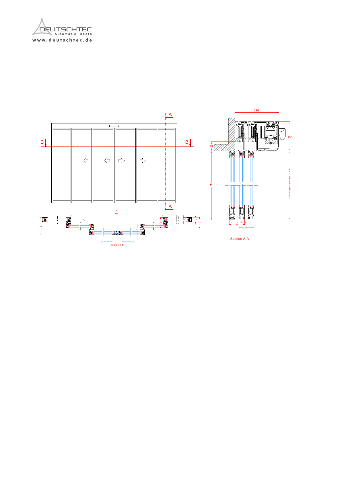
3.3.1 Two-leaves door version (TBS)
3.3 Technical Drawings
16 EN.09.09052022
3.2 Required Tools
2.5 & 3 & 4 & 5 & 6
Drill (+ masonry drill)
6, 8 und 10 mm
These are required tools for the door installation.
15 EN.09.09052022
- Beware of glass breakage and resulting injuries.
- Beware of moving parts in the drive.
- Do not touch the electronic board. Make sure to touch an earthed metal prior to having contact with the module.
- Secure the cables inside the drive by the cable ties.
- Before activating the mechanical part, make sure that the surrounding is clear of any object. Moving parts can draw
loose cables, hair or clothing into the system.
- Do not carry/move the glazing alone.
- Beware of sharp components in the drive.
- Attach signage and pictograms to the locations specified in section 1.8.
3.3.1 Two-leaves door version (TBS)
3.3 Technical Drawings
16 EN.09.09052022
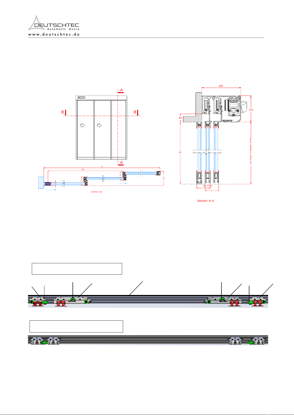
3.3.2 One-leaf door version (TBS Frame)
Note: The focus of this manual, within the assembly section, is on a two leaves version of the door but it is roughly
analogous with the one leaf version apart from positional differences on the rail.
3.4 Part´s Position s
EN.09.09052022 18 EN.09.09052022
1 2
3 4
5
5 6
Low-Speed Rail Hanger Assembly
High-Speed Rail Hanger Assembly
5 5
17
Art.-No. DescriptionPosition

19 EN.09.09052022 20 EN.09.09052022
Note: This installation manual is based on TL-series.
3.5.1 Check leaves & opening dimensions:
3.5. Installation Steps
Note: In the cases that the height difference between ceiling and the top surface of back
profile is limited and there is not sufficient space to install the rail and use demanded tools.
Ensure that the top of back profile is at least 20 mm lower than the ceiling. Please note that
it is important to consider proper covering component before the installation procedure.
This manual suits for next models
1
Table of contents
Other DEUTSCHTEC Door Opening System manuals


Popular Door Opening System manuals by other brands


Johnson Controls
Johnson Controls PGP303 installation guide

Carbine
Carbine CDC-5 instructions

Roca
Roca MOTION manual

WSS
WSS SPRINT Slide Line Original Assembly and Maintenance Instructions

Cal-Royal
Cal-Royal N-77CVR installation instructions

Roger Technology
Roger Technology R41 Series Instructions and Recommendations

WSS
WSS SPRINT NOVA 80 Assembly and operating instructions

Assa Abloy
Assa Abloy Yale 1105 installation instructions

Eco
Eco TS-50 Assembly instruction

Telcoma
Telcoma STAR Series INSTRUCTION HANDBOOK AND SPARE PARTS CATALOGUE

GEZE
GEZE Slimdrive EMD Replacement instructions

BWI
BWI 2000V Series installation instructions