NIVELCO UNICONT PMG-500 Owner's manual

2 pmg511en21p01
CONTENTS
1. INTRODUCTION.................................................................................................................................................................... 4
2. SPECIFICATIONS.................................................................................................................................................................. 4
2.1 General Data.................................................................................................................................................................. 4
2.2 Accessories .................................................................................................................................................................... 5
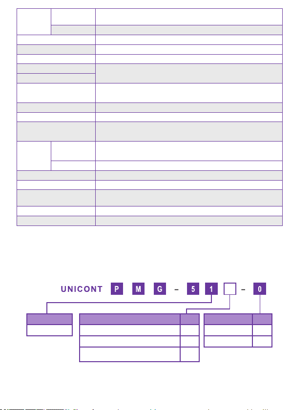
2.3 Order Code..................................................................................................................................................................... 5
2.4 Outlines and Dimensions .............................................................................................................................................. 6
3. MOUNTING............................................................................................................................................................................ 6
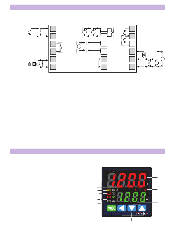
4. WIRING .................................................................................................................................................................................. 7
5. PROGRAMMING ................................................................................................................................................................... 7
5.1 Parts and Display ........................................................................................................................................................... 7
5.2 Startup............................................................................................................................................................................ 9
5.3 Input Settings [PAR3 → IN-T]........................................................................................................................................ 9
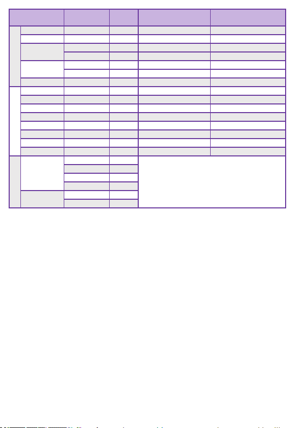
5.3.1 Input Types [PAR3 → IN-T].................................................................................................................................. 9
5.3.2 Sensor Temperature Unit .................................................................................................................................... 10
5.3.3 Analog Input Scale Value Settings ...................................................................................................................... 10
5.3.4 Low-Limit Input Value [PAR3 → L-RG]............................................................................................................... 11
5.3.5 Upper-Limit Input Value [PAR3 → H-RG]........................................................................................................... 11
5.3.6 Scale Decimal Point Position [PAR3 → DOT].................................................................................................... 11
5.3.7 Lower Limit Scale Value [PAR3 → L-SC] ........................................................................................................... 11
5.3.8 Upper Limit Scale Value [PAR3 → H-SC]........................................................................................................... 11
5.3.9 Input Offset Correction [PAR3 → IN-B] .............................................................................................................. 11
5.3.10 Input Digital Filter [PAR3 → MAvF] .................................................................................................................. 12
5.3.11 Upper Limit [PAR3 → H-SV] and Lower Limit of Set Value (SV) [PAR3 → L-SV] ........................................... 12
5.4 Output Settings............................................................................................................................................................. 12
5.4.1 Selecting a Control Output [PAR3 → OUT2]...................................................................................................... 12
5.4.2 SSR Function [PAR3 → O2.SR]......................................................................................................................... 12
5.4.3 Current Loop Output Range Settings [PAR3 → O2MA]..................................................................................... 12
5.5 Control Output.............................................................................................................................................................. 13
5.5.1 Heating Control [PAR3 → O-FT → HEAT] or Cooling Control [PAR3→ O-FT → COOL]................................ 13
5.5.2 Heating & Cooling Control [PAR3 → O-FT → H-C]........................................................................................... 13
5.5.3 Deadband/Overlap Band [PAR2 → DB]............................................................................................................. 14
5.5.4 MV Upper Limit Value [PAR2 → H-MV] and MV Lower Limit Value [PAR2 → L-MV]........................................ 17
5.5.5 MV Settings for Sensor Break Error [OPEN] [PAR5 → ErMV] .......................................................................... 18
5.5.6 Ramp Settings [PAR2 → RAMU/ RAMD/ rUNT] ................................................................................................ 18
5.5.7 Auto/Manual control settings............................................................................................................................... 19
5.5.7.1 Switching Between Manual/Auto Control................................................................................................. 19
5.5.7.2 Initial MV for Manual Control [PAR5 → ItMV].......................................................................................... 20
5.5.7.3 Initial MV Manual Control [PAR5 → PrMV] ............................................................................................. 21
5.6 Temperature Control..................................................................................................................................................... 21
5.6.1 Temperature Control Mode [PAR3 → C-MD]...................................................................................................... 21
5.6.2 ON/OFF Control with Hysteresis Function [PAR3 → C-MD → ONOF] ............................................................. 21
5.6.3 PID Control [PAR3 → C-MD → PID] ................................................................................................................. 22
5.6.3.1 Setting the Proportional Band for Heating [PAR2 → H-P] and Cooling [PAR2 → C-P].......................... 23
5.6.3.2 Setting Integral Time for Heating [PAR2 → H-I] and Cooling [PAR2 → C-I] .......................................... 23
5.6.3.3 Setting Differential Time for Heating [PAR2 → H-D] and Cooling [PAR2 → C-D] .................................. 23
5.6.3.4 Setting Control Period for Heating [PAR3 → H-T] and Cooling [PAR3 → C-T]...................................... 23
5.6.3.5 Offset Correction / Manual Reset Settings [PAR2 → REST] .................................................................. 23
5.6.4 Auto-Tuning......................................................................................................................................................... 24
5.6.4.1 Auto-Tuning ON/OFF [PAR2 → AT] ........................................................................................................ 24
5.6.5 Auto-Tuning Mode Settings [PAR3 → AT.t]......................................................................................................... 24

pmg511en21p01 3
5.7 Alarm Output ................................................................................................................................................................ 25
5.7.1 Alarm Operation [PAR4 → AL-1]........................................................................................................................ 25
5.7.2 Alarm Output Settings [PAR4 → AL1T].............................................................................................................. 26
5.7.3 Alarm Output Lower [PAR1 → AL1L] and Upper [PAR1 → AL1H] Limit Value Settings ................................... 27
5.7.4 Alarm Output Hysteresis [PAR4 → A1HY].......................................................................................................... 27
5.7.5 Alarm N.O./N.C. [PAR4 → A1N]......................................................................................................................... 27
5.7.6 Alarm Output Delay Settings [PAR4 → A1ON / A1OF]....................................................................................... 27
5.7.7 Loop Break Alarm (LBA) [PAR4 → AL-1/ → LBA] ............................................................................................. 28
5.7.8 LBA Monitoring Period [PAR4 → LBaT] ............................................................................................................. 29
5.7.9 LBA Detection Band [PAR4 → LBaB]................................................................................................................. 29
5.7.10 Sensor Break Alarm [PAR4 → AL-1 → SBA]................................................................................................... 30
5.7.11 Heater Burnout Alarm [PAR4 → AL-1 → HBA]................................................................................................ 30
5.7.12 Alarm Output Deactivation [PAR5 → DI-K→ ALRE]........................................................................................ 31
5.7.13 Alarm Output Examples .................................................................................................................................... 32
5.8 Analog Transmission.................................................................................................................................................... 33
5.8.1 Analog Transmission Output Value Settings [PAR4 → AoM1] ........................................................................... 33
5.8.2 Transmission Output Upper / Lower Limit Value Settings [PAR4 → FsL1/ FsH1].............................................. 33
5.9 Communication ............................................................................................................................................................ 33
5.9.1 Unit Address Settings [PAR4 → ADRS] ............................................................................................................. 34
5.9.2 BPS (Bits Per Second) Settings [PAR4 → BPS]................................................................................................ 34
5.9.3 Communication Parity Bit [PAR4 → PRTY]........................................................................................................ 34
5.9.4 Communication Stop Bit Settings [PAR4 → STP].............................................................................................. 34
5.9.5 Response Timeout Settings [PAR4→ RSwT]..................................................................................................... 34
5.9.6 Enable / Disable Communication Writing [PAR4→ COMW]............................................................................... 35
5.10 Other Functions.......................................................................................................................................................... 35
5.10.1 Heating MV Monitoring ..................................................................................................................................... 35
5.10.2 Cooling MV Monitoring...................................................................................................................................... 35
5.10.3 Heating Current Monitoring [PAR1 → CT-A] .................................................................................................... 35
5.10.4 RUN/STOP [PAR1 → R-S]............................................................................................................................... 35
5.10.4.1 Stop Control Output Settings................................................................................................................. 36
5.10.4.2 Stopping the Alarm Output [PAR5 → StAL] .......................................................................................... 36
5.10.5 Multi SV............................................................................................................................................................. 36
5.10.5.1 The Number of Multi SVs [PAR5 → MtSV] ........................................................................................... 36
5.10.5.2 Selecting the Multi SV Number [PAR1 → SV-N]................................................................................... 36
5.10.5.3 Multi SV Settings [PAR1 → SV-0/ SV-1] ............................................................................................... 36
5.10.6 Digital Input ....................................................................................................................................................... 36
5.10.6.1 Digital Input Terminal Settings [PAR5 → DI-1]...................................................................................... 36
5.10.6.2 Digital Input Button Setting [PAR5 → DI-K]........................................................................................... 37
5.10.7 User Level Settings [PAR5 → USER] .............................................................................................................. 37
5.10.8 SV Group Lock [PAR5 → LcSV]....................................................................................................................... 37
5.10.9 Parameter Group Lock [PAR5 → LcP1/LcP2/LcP3/LcP4/LcP5] ...................................................................... 37
5.10.10 Reset Parameter [INIT] ................................................................................................................................... 37
5.10.11 Password Settings [PAR5 → PWD]................................................................................................................ 38
5.10.11.1 Setting up a Password [PASS].............................................................................................................38
5.10.11.2 Reset Password................................................................................................................................... 38
6. ERROR CODES................................................................................................................................................................... 39
7. MAINTENANCE, REPAIR, AND STORAGE ....................................................................................................................... 40
8. MENU MAP..................................................................................................................................................................ANNEX

4 pmg511en21p01
Thank you for choosing a NIVELCO product!
1. INTRODUCTION
In addition to the 1/16 DIN (48 x 48 mm) design, the UNICONT PM universal controller family is characterized by
easy setpoint adjustment and easy programming. The universal analog PID controller is suitable for processing
signals from Pt100 resistance thermometers, various thermocouples, and transmitters with a 4…20 mA
and 0…10 V DC, 0…5 V DC, 1…5 V DC, 0…100 mV DC signal. The control output can be a relay, a continuous
0…20 mA or 4…20 mA current signal, or an output suitable for operating an SSR (solid-state relay). The self-
learning autotuning (AT) mode helps users determine PID parameters. The device provides automatic wire
compensation for the Pt100 input signal and automatic cold junction compensation for the thermocouple input
signal. Some PM–500 series members are also capable of RS485 communication.
The UNICONT PM–500 enables more efcient control with a super-fast 50 ms sampling cycle and ±0.3% display
accuracy. Moreover, it supports a variety of control modes, including simultaneous control of heating and cooling
and automatic/manual control and communication functions.
2. SPECIFICATIONS
2.1 GENERAL DATA
PMG–500
Power
supply
AC 100…240 V AC, 50/60 Hz, 8 VA
AC/DC 24 V AC 50/60 Hz, 8 VA or 24…48 V DC, 5 W
Voltage tolerance ±10% deviance from nominal voltage
Ambient temperature –10…+50 °C
Ambient humidity 35...85% RH
Display
Process Value (PV): 7-segment, red, 7.0 × 14.0 mm,
Set Value (SV): 7-segment, green, 5.0 × 10.0 mm
Status LEDs with labels
Primary
input
RTD mode Compatible resistance temperature sensors: JPt 100Ω, DPt 100Ω, DPt 50Ω,
Cu 100 Ω, Cu 50 Ω, and Nikel 120 Ω
TC mode Compatible thermocouple sensors: K, J, E, T, L, N, U, R, S, B, C, G, and PLII
Analog mode Voltage: 0…100 mV, 0…5V, 1…5 V, and 0…10 V
Current: 0…20 mA and 4…20 mA
Optional
inputs
CT input 0…50 mA (for external 1/1000 CT connection)
Digital input (DI)
Active input for passive switches, measuring current: 0.5 mA / 5 V
Contact switch – sensing threshold: ’On’ < 2 kΩ / ’Off’ > 90 kΩ
Transistor switch – sensing threshold: ’On’ < 1.0 V DC / ’Off’ < 0.1 mA
Display
accuracy
RTD mode Room temperature (23 °C ±5 °C): (PV ±0.3% or ±1 °C) ±1 digit
Full ambient-temperature range: (PV ±0.5% or ±2 °C) ±1 digit
TC mode
Analog mode Room temperature (23 °C ±5 °C): ±0.3% F.S. ±1 digit
Full ambient-temperature range: ±0.5% F.S. ±1 digit
CT input ±5% F.S. ±1 digit
Control
outputs
Relay (OUT1 / 2) 250 V / 3 A AC-1
SSR (OUT2) 11 V DC ±2 V / 20 mA
Current (OUT2) 4…20 mA or 0…20 mA selectable (max. loop resistance 500 Ω)
Alarm output Relay (AL1) 250 V / 3 A AC-1

pmg511en21p01 5
Optional
outputs
Transmitter
output 4...20 mA: output accuracy ±0.3% F.S (max. loop resistance 500 Ω)
Communication RS485 communication Modbus RTU protocol
Control algorithms: ON/OFF, P, PI, PD, PID
Hysteresis RTD / Thermocouples: 1…100 °C (0.1…100 °C)
Proportional band (P) 0.1…999.9 °C (0.1…999.9%)
Integral time (I) 0…9999 s
Differential time (D)
Control period (T) Relay output, SSR driver output: 0.1…120.0 s
Current loop output + SSR driver output: 1.0…120.0 s
Manual reset value 0…100%
Sampling period 50 ms
Vibration resistance 0.75 mm amplitude at frequency 5 to 55 Hz (for 1 min)
in each X, Y, Z direction for 2 hours
Relay life
cycle
Mechanical OUT1/OUT2: min. 5,000,000 operations
AL1: min. 20,000,000 operations
Electrical OUT1/OUT2, AL1: min. 100,000 operations
Memory retention ~10 years (non-volatile semiconductor memory)
Ingress protection Behind mounting plane: IP20, front panel: IP54
Insulation type Reinforced insulation between the input and the power part
(dielectric breakdown: 2 kV)
Bounding box size 48 x 48 x 70.5 mm
Weight ~105 g
2.2 ACCESSORIES
– 1 User’s and Programming Manual
– 1 Mounting bracket
– 1 Warranty card
– 1 EU declaration of conformity
2.3 ORDER CODE
Output Code
R1, R2 relays, Iout, AL1 relay 1
R1 relay, SSR1 / 4…20 mA, AL1 relay 2
R1 relay, SSR1 / 4…20 mA, AL1 relay,
RS485 3
Supply voltage Code
100…200 V AC 1
24 V AC/DC 2
Input
1 universal input
Legend:
Iout: 0/4…20 mA output, which can be control or transmitter type
SSR1: Solid-state relay driver output AL1: Closing contact relay output
RS485: Series line connection with Modbus RTU protocol

6 pmg511en21p01
2.4 OUTLINES AND DIMENSIONS
The device can be mounted in a 48x48 mm cutout (1/16 DIN board instrument).
The insertion depth is 64.5 mm, other main dimensions are shown in the gure.
PMG–5
Front Side
48
45
1.7
664.5
Mounting Bracket
31
20
15
21
5
45
16
48.6
44.9
36
55
56
3. MOUNTING
The panel is mounted on the front panel in a 1/16 DIN (48 x 48 mm) cutout with the supplied mounting frame. Make
sure that the rubber seal ts, which ensures tightness from the front. When installing multiple instruments, ensure
adequate distances. Insert the unit into the bracket panel and secure the bracket with a straight screwdriver
(-)
Tightening the mounting bracket Minimum distance between devices
A – min. 65 mm C – 450
+0.6 mm
B – min. 65 mm D – 450
+0.6 mm
D
B
C
A

pmg511en21p01 7
4. WIRING
DI-1
RS485 (B
-
)
RS485 (A+)
RTD TC Sensor
CT
1
2
3
4
5
6
7
8
9
10
11
13
14
15
16
17
18
A
B
B'
V
mA
mA
DI-1
-
+
Digital input,
Non-contact,
Contact input
Output
1
Relay
250 V
3 A AC–1
Resistive load
Supply voltage
1
00…240 V AC 50/60 Hz 8 VA
2
4 V AC 50/60 Hz 8 VA
2
4…48 V DC 5 W
V
mA
DC
0/4…20 mA
Max. load 500 Ω
SSR
11 V DC ±2 V
Max. 20 mA
AL1 output
250 V 3 A AC–1
Resistive load
Output 2
Relay
250 V 3 A AC–1
Resistive load
Current
transformer (CT)
0.0…50.0 A
Transmitter
output
4…20 mA
DC
12
Ally types have colored connection points. Other connection point types depend on the particular variant.
Important information for proper use:
– The digital input is not electrically isolated from internal circuits, so it must be insulated if it is connected
to another circuit.
– Make sure that the connection polarity of the temperature sensor or analog input is correct.
– Make sure the polarity of the power supply is correct.
–Do not swap the output and input terminals.
–For thermocouple sensors, use a compensation cable with the same specifications as the input sensors.
Using an extension cord of different specifications and/or materials makes temperature sensing less
accurate. For more reliable operation, choosing a high-grade compensation cable is recommended.
–Do not place sensor wires near AC wires.
– Do not attach communication cables to the AC power cord. Use only twisted-pair wires for communication
cabling. The length of the communication cable must not exceed 800 meters.
5. PROGRAMMING
5.1 PARTS AND DISPLAY
The seven-segment displays show the measured (Process
Value, PV) and set values (SV) in regular operation, while
in other modes, they show the corresponding text signals
and values according to the current status of programming
and setting. Use the 4 buttons to operate the menu system
and perform programming. 6
1
3
2
8
7
4
5
910
11

8 pmg511en21p01
1. Measured Value (PV):
RUN mode: it shows the currently measured value (PV).
Setting mode: it shows the name of the parameter.
2. Set value (SV):
RUN mode: it shows the set value (SV).
Setting mode: it shows the the parameter value.
3. Unit (°C / °F / %) indicator: It displays the unit set in parameter group 3. The unit applies to the displayed
values of the PV and SV.
4. Manual control indicator (MAN): it switches on during manual control.
5. Multi SV indicator (SV1, SV2, SV3) LEDs: Indicates the different target value setting currently in use
(SV1-3). The base destination eld (SV0) is valid if none is active. Not available for all models.
6. Auto-tuning indicator (AT): ashes every 1 second when auto-tuning is executed.
7. Alarm output (AL1) indicator: it turns on when the alarm output is on.
8. Control output (OUT1, OUT2) indicator: it turns on when the corresponding control output is active. During
manual control, it switches off if the measured value is 0.0% when using a current output; otherwise, it is
switched on continuously. During automatic control, it switches on when the measured value exceeds 3.0%
and switches off when it falls below 2.0%.
9. button: It is used when entering parameter group, returning to RUN mode, moving parameter, saving
the set value
Functions:
9.1 Press and hold the button for longer than 2 seconds in RUN mode to enter Setting mode.
9.2 Press and hold the button for 1.5 seconds to enter another parameter group in Setting mode.
9.3 Press and hold the button for longer than 3 seconds in to return to RUN mode from Setting mode.
9.4 Press and hold the button at the last parameter name of any parameter group, and the device
returns to the current main parameter group, where other parameter groups can be accessed.
9.5 If no button is pressed within 30 seconds in setting mode, the device will automatically return to RUN
mode, and the previously saved setting value will be retained.
10. buttons: they are used when entering the set value, changing mode, navigating between
parameters/values, and changing values up/down.
11. Digital input key: When pressing the buttons together for 3 seconds, it operates the
RUN/STOP, alarm clear, and auto tuning functions.

pmg511en21p01 9
The characters of the 7-segment display
5.2 STARTUP
When energized, the display will ash for one second, at which point all display sections will illuminate. Then the
hardware ID code and the input sensor type will ash twice, and the unit will switch to RUN mode. If ‘Open’ is
displayed, there is no source or there is a contact error on the universal input.
In RUN mode, the current temperature or the value provided by the sensor is displayed.
The parameters in each group are related to each other, so please follow the parameter order below.
Parameter group 3 [PAR3] → Parameter group 4 [PAR4] → Parameter group 5 [PAR5] →
Parameter group 2 [PAR2] → Parameter group 1 [PAR1] → SV Setting [SV]
Note: Changing the parameters of parameter group 3 can sometimes restore other related parameters. Always check that
such parameters are not affected.
5.3 INPUT SETTINGS [PAR3 →IN-T]
For normal operation, the universal input must rst the universal input must be set in ‘Setting’ mode. Then the
input type must be selected according to table 5.3.1 Input types. Default setting: KCaH.
5.3.1 Input Types [PAR3 → IN-T]
The device supports multiple input types, allowing the user to choose from various thermocouples, resistors,
and analog voltages/currents.
Input type Accuracy Indication Temperature range (°C) Temperature range (°F)
Thermocouple (TC)
K (CA) 1KCaH –200…1350 –328…2463
0.1 KCaL –199.9…999.9 –199.9…999.9
J (IC) 1JIcH –200…800 –328…1472
0.1 JIcL –199.9…800.0 –199.9…999.9
E (CR) 1ECrH –200…800 –328…1472
0.1 ECrL –199.9…800.0 –199.9…999.9
T (CC) 1TCcH –200…400 –328…752
0.1 TCcL –199.9…400.0 –199.9…752.0
B (PR) 1B PR 0…1800 32…3272
R (PR) 1 R PR 0…1750 32…3182
S (PR) 1 S PR 0…1750 32…3182
N (NN) 1N NN –200…1300 –328…2372

10 pmg511en21p01
Input type Accuracy Indication Temperature range (°C) Temperature range (°F)
Thermocouple (TC)
C (TT) 1C TT 0…2300 32…4172
G (TT) 1G TT 0…2300 32…4172
L (IC) 1LIcH –200…900 –328…1652
0.1 LIcL –199.9…900.0 –199.9…999.9
U (CC) 1UCcH –200…400 –328…752
0.1 UCcL –199.9…400.0 –199.9…752.0
Platinel II 1 PLII 0…1390 32…2534
RTD
Cu 50 Ω 0.1 CU 5 –199.9…200.0 –199.9…392.0
Cu 100 Ω 0.1 CU10 –199.9…200.0 –199.9…392.0
JPt 100 Ω 1JPtH –200…650 –328…1202
JPt 100 Ω 0.1 JPtL –199.9…650.0 –199.9…999.9
DPt 50 Ω 0.1 DPt5 –199.9…600.0 –199.9…999.9
DPt 100 Ω 1DPtH –200…650 –328…1202
DPt 100 Ω 0.1 DPtL –199.9…650.0 –199.9…999.9
Nickel 120 Ω 1NI12 –80…200 –112…392
Analog
Voltage
0 … 10 V AV1
–1999 … 9999
(The display point changes according to the decimal point)
0 … 5 V AV2
1 … 5 V AV3
0 … 100 mV AMV1
Current 0 … 20 mA AMA1
4 … 20 mA AMA2
Note: If the input specication is changed, the upper / lower limits of the SV will be automatically set to the maximum/
minimum values of the new specication for the temperature sensors. For analog inputs, it sets the analog upper/lower
input values to the max/min temperature range and the SV upper/lower limits to the upper/lower scale values. Therefore,
the settings need to be recongured.
5.3.2 Sensor Temperature Unit
When the input temperature sensor is selected, the [PAR3 - UNIT] can be set to display the desired unit (°C, °F).
However, this parameter is not displayed when an analog input is selected. The default unit is °C
When analog input is selected, it is possible to specify the unit [PAR3 - dUNT] (°C, °F,%, OFF). When OFF is
selected, the displayed unit is not specied. The LED unit display does not turn on. The default setting is %.
5.3.3 Analog Input Scale Value Settings
By selecting the analog input, the analog input range (upper / lower input limits) and the display scale (upper /
lower scale limits) within the selected input range can be set.
For analog input, ±5% of the set upper / lower limit is extended. The analog output is also expanded by comparing
the input value. (Using a ±5% extension for a temperature sensor input within the temperature range.)
Note: If the upper and lower limit scale settings are the same, ERR will ash twice, and the Setting mode will be displayed.

pmg511en21p01 11
Upper scale limit +10%
Upper scale limit +5%
Upper scale limit
Upper limit
Lower limit
Lower scale limit
Lower scale limit –5%
Lower scale limit –10%
12 1 1 32 2 1 1
No. PV Display
1±5% section PV ashes
2±5 to 10% section HHHH or LLLL ashes
3Over ±10% section OPEN ashes
5.3.4 Low-Limit Input Value [PAR3 → L-RG]
The actually used lower limit values can be set within the analog input range. The temperature range from the
minimum value to the upper limit [H-RG] - F.S. adjustable up to 10%. Default: 0.
5.3.5 Upper-Limit Input Value [PAR3 → H-RG]
The actually used limit values can be set within the analog input range. The lower input limit [L-RG] + F.S. can be
set from 10% to the maximum value of the temperature range. Default: 10.
5.3.6 Scale Decimal Point Position [PAR3 → DOT]
The decimal point position can be set for Current Measured Value (PV) and Set Value (SV) on the upper and
lower limit scales. Available settings: 0000 / 000.0 / 00.00 / 0.000. Default: 000.0.
5.3.7 Lower Limit Scale Value [PAR3 → L-SC]
Sets the display scales for the lower limits of the analog input [L-RG]. (Based on the decimal point setting.)
Default: 0
5.3.8 Upper Limit Scale Value [PAR3 → H-SC]
Sets the display scales for the upper limits of the analog input [H-RG]. (Based on the decimal point setting.)
Default: 100.
5.3.9 Input Offset Correction [PAR3 → IN-B]
This function is used to correct the offset provided by thermocouples, RTDs, or analog input devices. The input
correction function is mainly used when the sensor cannot be xed directly to the controlled objects. Temperature
difference compensation must be performed between the sensor installation point and the actual measuring
point. Default setting: 0, unit: °C / °F / -.
Example: If the controller shows 78 °C when the actual temperature is 80 °C, set the input correction [IN-B]
to “002” to set the temperature displayed on the controller to 80 °C.
Note: If the Process Value (PV) of each input sensor after input correction is out of the input range, “HHHH” or “LLLL”
will appear on the display. Make sure that an accurate temperature variance measurement is performed before setting
the input correction. Inaccurate initial measurement may result in greater deviation.

12 pmg511en21p01
5.3.10 Input Digital Filter [PAR3 → MAvF]
Stable control is not possible if the Process Value (PV) uctuates due to rapid input signal changes. Using the
input digital lter function stabilizes the PV for more reliable control. Default setting: 0.1 s.
Example: If the digital input lter is set to 0.4 seconds, the digital lter applies to the sampling value collected in
0.4 seconds. (400 ms).
Note: The Process Value (PV) may differ from the actual input value when using the digital input lter.
5.3.11 Upper Limit [PAR3 → H-SV] and Lower Limit of Set Value (SV) [PAR3 → L-SV]
The Set Value (SV) range can be limited within the temperature range of the temperature sensor or analog input
to prevent system control by improper SV.
Parameter Description / Range Default
H-SV SV lower limit +1 digit to upper limit value of sensor input or analog
scale
1350 (temperature) °C / °F
000.0 (analog)
L-SV Lower limit value of sensor or analog scale to SV upper-limit -1 digit –200 (temperature) °C / °F
100.0 (analog)
Note: Setting values outside the min/max input range or analog upper/lower limits is impossible. The previous settings are
retained instead of such values. The Setpoint (SV) can only be set within the lower limit of SV [L-SV] and the upper limit of
SV [H-SV]. The lower limit of SV [L-SV] must not exceed the upper limit of SV [H-SV].
5.4 OUTPUT SETTINGS
5.4.1 Selecting a Control Output [PAR3 → OUT2]
On models with a current loop output, current (CURR) or SSR drive output can be selected. Default setting: SSR.
5.4.2 SSR Function [PAR3 → O2.SR]
The SSR function only works with standard output [STND] on current models, so additional settings are not
available.
The way the load is controlled works the same way as the relay output type. (ON: 100% output level, OFF: output
level 0%)
AC
OUT
ON OFF ON OFF
5.4.3 Current Loop Output Range Settings PAR3 → O2MA]
If the control output is set to current output (CURR), the current output’s upper and lower limit range can be
4… 20 mA or 0… 20 mA. O2MA: Sets the current output range of OUT2.
Note: This parameter is only available on models that support [OUT2] current output.

pmg511en21p01 13
5.5 CONTROL OUTPUT
Output modes for general temperature control include heating mode or cooling mode and heating and cooling mode.
Heating control and cooling control are opposite operations with inverted outputs. The PID t i m e constant va r i e s de-
pending on the characteristics of the section controlled during PID control. The value of the control output is MV
(Manipulated Variable). MV is a percentage value that controls the switching of the assigned device output
according to the settings.
0%
Heating control (inverted operation)
PV
Control output
(MV)
100.0%
0%
Cooling control (normal operation)
PV
Control output
(MV)
100.0%
Setting group Parameter Range Default
PAR3 O-FT Standard model: HEAT / COOL HEAT
Heating/cooling model: HEAT / COOL / H-C H-C
5.5.1 Heating Control [PAR3 → O-FT → HEAT] or Cooling Control [PAR3→ O-FT → COOL]
Heating control mode: If the Process Value (PV) falls below the Set Value (SV), the output will power the heater.
Cooling Control Mode: If the Process Value (PV) rises above the Set Value (SV), the output will power the cooler.
5.5.2 Heating & Cooling Control [PAR3 → O-FT → H-C]
Heating and cooling control mode: heating and cooling with a single temperature controller if it is difcult to cont-
rol the temperature of the object by heating or cooling alone. The heating and cooling control mode uses different
PID time constants to control heating and cooling. It is possible to set the heating and cooling control in both PID
control and ON / OFF control modes.
For heating and cooling control, the relay control output OUT1 is assigned to the heating control, and the SSR
/ current control output OUT2 is assigned to the cooling control. Note that the OUT2 SSR drive output uses
standard (on / off) control.
Cooling load
Heating load
Temperature drop
Temperature
increase
Temperature sensor input
(feedback)
Cooling control output
Temperature
controller
Cooling
control
Heating
control
Heating control output

14 pmg511en21p01
5.5.3 Deadband/Overlap Band [PAR2 → DB]
It is possible to assign a deadband between the heating and cooling control bands based on the Set Value (SV) for
heating and cooling. A deadband is formed around the SV when a positive (+) value is set. There is no regulation in
the deadband, so the heating and cooling MV (Manipulated Variable) will be 0.0% in the deadband formed. When
the negative (-) value is set, an overlap band (simultaneous heating and cooling MVs) is formed around the SV.
Set to 0 if no deadband or overlap band is used.
When setting the integral time, this applies if the integral time for the heating control and cooling control is set.
It also acts as a P-P controller for PI-P control and P-PI control.
Ranges and default settings:
[OUT1 / OUT2]: PID / PID, PID / ON-OFF, and ON-OFF / PID control
–Set the range (temperature): – (proportional band) + (proportional band)
(lower value when using different proportional bands)
–Set the range (analog): –99.9…+99.9
–Default: 0000 (temperature H),000.0 (temperature L, analog),
(unit: temperature °C / °F, analog % F.S.)
[OUT1 / OUT2]: ON-OFF / ON-OFF control
–Set the range (temperature):
–999 (overlapping band) –0000 (not used) –+999 (deadband) (temperature H)
–199.9 (overlapping band) –000.0 (not used) –+999.9 (deadband) (temperature L)
–Set the range (analog): –99.9 (overlap band) 000.0 (not used) –099.9 (deadband)
–Default: 0000 (temperature H), 000.0 (temperature L, analog),
(unit: temperature °C / °F, analog % F.S.)
Using the deadband:
When db is in 10 digits
Heating MV SV-5
SV-5 Process value
ON
SV+5
Deadband
Deadband
Cooling MV
Heating control
Heating control
Cooling control
Heating control
Control output MV
Control output MV
PID heating control and PID cooling control
Heating proportional band
Heating proportional band Cooling hysteresis/offset
100.0%
100.0%
Cooling proportional band
% FS analog
PID heating control and ON/OFF cooling control

pmg511en21p01 15
Overlap band
Heating control Cooling control
PID heating control and ON/OFF cooling control
When db is
in -10 digits Heating proportional band Cooling hysteresis/offset
100.0%
Process valueHeating MV SV+5
When db is in 10 digits
SV+5
SV+5SV-5
SV-5
ON
Cooling MV
Process value
Process value ON
ON
Deadband
Deadband
Overlap band
Heating control
Heating control
Heating control
Cooling control
Cooling control
Cooling control
Control output MV
Control output MV
Cooling proportional band
Cooling hysteresis/offset
Heating hysteresis/offset
100.0%
ON/OFF heating control and PID cooling control
ON/OFF heating control and ON/OFF cooling control
PID heating control and PID cooling control
Using Overlap Band
When db is in -10 digits Control output MV % FS analog
Heating proportional band Cooling proportional band
100.0%
Cooling MVHeating MV SV+5

16 pmg511en21p01
Overlap band
Overlap band
Heating control
Heating control
Heating control
Heating control
Cooling control
Cooling control
Cooling control
Cooling control
ON/OFF heating control and PID cooling control
ON/OFF heating control and ON/OFF cooling control
PID heating control and PID cooling control
PID heating control and ON/OFF cooling control
When db is
in -10 digits
When db is
in -10 digits
When db
is in 0 digit
When db
is in 0 digit
Control output MV
Control output MV
Control output MV
Control output MV
Cooling proportional band
Cooling hysteresis/offset
Heating hysteresis/offset
Heating proportional band
Cooling proportional band
Cooling hysteresis/offset
100.0%
Cooling MV
Process value
Process value SV-5
SV-5
% FS analog
100.0%
100.0%
0.0% (SV)
OFF 0.0% (SV) ON
Heating MV
Heating MV
Cooling MV
Process value
SV+5
Using neither a deadband nor an overlap band

pmg511en21p01 17
Heating control Cooling control
Cooling controlHeating control
ON/OFF heating control and PID cooling control
ON/OFF heating control and ON/OFF cooling control
When db
is in 0 digits
When db is
in 0 digits
Control output MV
Control output MV
Heating hysteresis/offset
100.0%
OFF 0.0% (SV)
OFF (SV)
ON
ON ON
Process value Cooling MV
Present value
Cooling proportional band
Cooling hysteresis/offset
Note: Actual operation may differ depending on the set value of the heating integration time [H-I] and the cooling
integration time [C-I].
5.5.4 MV Upper Limit Value [PAR2 → H-MV] and MV Lower Limit Value [PAR2 → L-MV]
The upper / lower limits of the control output MV [H-MV / L-MV] can be set to the actual MV, provided that the MV
calculation of the temperature controller exceeds the limits.
When controlling heating and cooling, the cooling MV contains a „-” prex. Therefore, the upper limit displayed on
the heating side is +, and the lower limit is displayed on the cooling side.
Standard control (heating) Heating and cooling control
100%
MV upper limit
Control output
MV lower limit
0%
100%
MV upper limit
Control output
MV lower limit
0%
Heating control Heating control
Cooling control
PV
Parameter Description / Range Default
H-MV
Standard control: MV lower limit value [L-MV] +0.1…100.0 100.0%
Heating and cooling control: 000.0…100.0 (PID)
0.0 (OFF)/100.0 (ON) (ON/OFF) 100.0%
L-MV Standard control: 000.0…MV upper limit value [H-MV] –0.1 0.0%
Heating and cooling control: –100.0…000.0 (PID), –100.0 (ON) / 0.0 (OFF) (ON/OFF) –100.0%

18 pmg511en21p01
Note: The same MV limits apply during auto-tuning. The MV limits do not apply to manual control, MV when control is
stopped, MV sensor failure, and initial manual control. The MV upper / lower limit conguration is not available in the ON /
OFF standard control mode (heating or cooling control).
5.5.5 MV Settings for Sensor Break Error [OPEN] [PAR5 → ErMV]
In the event of an open sensor error, the output value of the controller can be set to a predened MV value instead
of ON / OFF or PID control. Ignores the MV based on the ON / OFF or PID control and sends a control value based
on the specied MV. Default setting: 0.0%
5.5.6 RAMP Settings [PAR2 → RAMU/ RAMD/ rUNT]
The ramp is a function that congures the temperature per unit time to the Setpoint (SV). The function limits the
rate of change of the Set Value (SV) and thus limits sudden temperature changes (increase and decrease) in
the control system.
The ramp is typically used in applications where rapid temperature changes (increase and decrease) can adver-
sely affect the controlled system.
Control is based on the changed SV (hereafter: RAMP SV) – based on the preset rate of change (temperature
changing per unit time). The RAMP uplink rate and the RAMP downlink rate can be congured independently.
Parameter Description / Range Default
RAMU Setting for RAMP-UP change rate 0 °C / °F / Digit
RAMD Setting for RAMP-DOWN change rate
rUNT RAMP time unit (SEC / MIN / HOUR) MIN
Note: Activating the RAMP function when RAMP is not operating limits the Set Value (SV) rate of change based on the
Process Value (PV). Changing the SV or RAMP parameters during RAMP operation limits the rate of change of SV based
on SV at the time of change.
The alarm occurs during the RAMP based on the nal SV. Setting the RAMP rate to 0 turns off the RAMP functi-
on. When the RAMP function is on, RAMP SV appears in the SV display area.
RAMP depending on operating status:
Operation Ramp UP/DOWN Ramp
All operations When 0 Inactive
OPEN, HHHH, LLLL, auto-tuning, switching from Auto to Manual,
switching from Run to Stop Regardless of status Inactive
OPEN, HHHH, LLLL, after Auto-tuning has nished, PV = SV Regardless of status Inactive
Switching ON, SV change, switching from Stop to Run, switching from
Manual to Auto, Ramp rate change When not 0 Active

pmg511en21p01 19
Ramp operation diagram
SV
SV
SV
SV
SV
SV
RAMP SV
= PV
Altered
SV
RAMP SV
RAMP SV
= PV
RAMP Start
Change point Change point
RAMP Start
RAMP time unit (s/m/h)
RAMP setting values
(1…9999 digit)
RAMP setting values
(1…9999 digit)
RAMP
activation zone
RAMP
activation zone
RAMP
activation zone
RAMP
activation zone
Time
Time Time
Time
Activating RAMP, when RAMP is off
Changing SV or RAMP parameter when RAMP is on
5.5.7 Auto/Manual control settings
The automatic mode is for the temperature to reach SV with the MV value calculated by the PID control.
The purpose of the manual mode is for the temperature to reach SV with a user-dened MV value.
Note: In manual mode, parameter settings can only be viewed and cannot be changed (except for lock parameters). If the
[DI-1] digital input terminal function is set to automatic / manual [MAN], the button and automatic/manual changeover
will not work with communication. If the unit is turned on after a power failure or shutdown, the previous mode (automatic
or manual) will be retained.
It is possible to switch to manual mode during STOP state. It is also possible to switch between automatic / manual
mode during adjustment, but automatic tuning will stop if manual control is switched on during automatic tuning.
If a sensor break alarm occurs in [SBA] normal mode, the MV [ErMV] sensor fault will occur. The MV settings for
manual and automatic control can be changed in this state.
Operational priority: Manual control > Stop > Open (sensor disconnected)
5.5.7.1 Switching Between Manual/Auto Control
Switching to manual mode for standard control (heating or cooling):
– In ‘Normal’ mode, press the button, and the device will switch to MV monitoring mode. The SV display
shows H(heating control) or C(cooling control) and shows MV, indicating the start of MV monitoring.
–If any of is pressed during MV monitoring, the MAN indicator will turn on, and the lowest
digit (100 digits) will flash to indicate that the manual control is active.

20 pmg511en21p01
–Press the button to move the flashing digit (100 → 101 → 102 → 103 → 100).
–Select the digit and configure the desired MV value with the buttons 0 → 1 → 2 → 3 →
4 → 5 → 6 → 7 → 8 → 9 → 0 using the buttons.
–In either state, press the button to end manual control. The MAN indicator light goes out, and the
system returns to automatic control mode.
Switching to manual mode for heating and cooling control:
– In ″Normal″ mode, press the button, and the heating MV supervision mode is activated.
The SV display shows "H" and the MV indicates the start of the heating MV monitoring.
–If one of the buttons is pressed while the heating MV is being monitored, the MAN
indicator light comes on, and the lowest digit (100 digits) flashes to indicate that the manual control has
been activated.
–Press the button to move the flashing digit (100 → 101 → 102 → 103 → 100).
–Select the digit and set the desired MV value with the buttons and switch between
0 → 1 → 2 → 3 → 4 → 5 → 6 → 7 → 8 → 9 → 0 using the buttons.
–Press the button again, and the cooling MV monitoring mode is activated. ‚C’ appears on the SV
display and MV indicates the start of cooling MV monitoring.
– The lowest digit (100 digits) will flash if any of the buttons are pressed during cooling
MV monitoring.
–Press the button to move the flashing digit (100 → 101 → 102 → 103 → 100).
–Select the digit and set the desired MV value by using the buttons, and use the
buttons to switch between 0 → 1 → 2 → 3 → 4 → 5 → 6 → 7 → 8 → 9 → 0.
–In any condition, press the button to end the manual control mode. The MAN indicator light goes
out, and the system returns to automatic control mode.
Note: After heating and cooling control, the system returns to automatic control in the order of heating monitoring, manual
heating control, cooling monitoring, and manual cooling control. To switch between automatic and manual mode, press the
button once. The heating MV remains valid during cooling monitoring and manual cooling control. When the [DI-1]
digital input function is set to AUTO / MANUAL [MAN], the button on the front panel and the auto / manual control
functions via communication do not work.
Switching Manual / Auto control using the digital input (DI) connector:
If the digital input function [DI-1] AUTO / MANUAL control switch is set to [MAN], turn on the DI to activate manual
mode (the MAN indicator lights up) and turn off the DI to activate automatic mode. If the digital input function is
automatic, it can only be monitored. If it is manual, it is possible to change the MV and monitor it.
Note: See 5.10.6 Digital Input for detailed information about the digital input (DI) terminal settings.
5.5.7.2 Initial MV for Manual Control [PAR5 → ItMV]
The initial MV value can be set when the device is switched from automatic [AUTO] to manual control [PrMU].
Default setting: AUTO.
–AUTO: automatically adjusted MV, as initial MV for manual control.
–PrMV: manually set initial MV [PrMV].
Note: When the power is turned back on, it starts with MV that was in use when the power was turned off.
Table of contents
Other NIVELCO Controllers manuals