NIVELCO UNICONT PMG-400 Owner's manual

pmg4111a0600p_01
1 / 24
UNICONT
PMG-400
Universal controller
and display unit
USER'S AND PROGRAMMING MANUAL
1
ST
edition
Manufacturer:
H-1043 Budapest, Dugonics u. 11.
Tel.: 889-0100 Fax: 889-0200
NIVELCO Process Control Co.
E-mail: sales@nivelco.com www.nivelco.com

2 / 24
pmg4111a0600p_01
TABLE OF CONTENTS
1. GENERAL DESCRIPTION .................................................................................................................... 3
2. ORDER CODE ....................................................................................................................................... 3
3. TECHNICAL DATA................................................................................................................................ 4
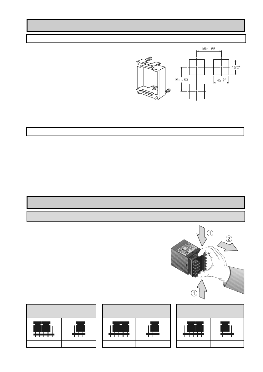
3.1 DIMENSIONS...................................................................................................................................... 4
3.2 ACCESSORIES ................................................................................................................................... 4
4. MOUNTING............................................................................................................................................ 5
5. WIRING .................................................................................................................................................. 5
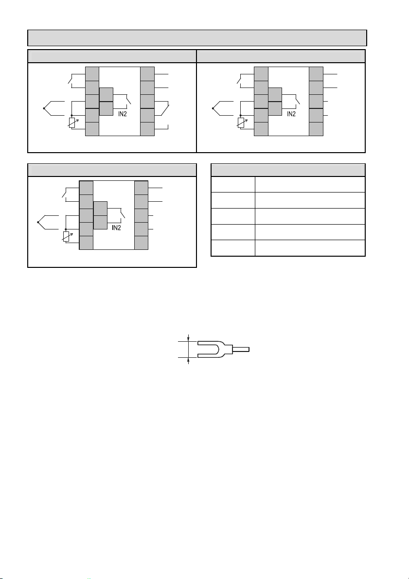
5.1 INPUT SELECTION............................................................................................................................... 5
5.2 WIRING POWER SUPPLY,INPUT/OUTPUT ............................................................................................ 6
6. CONTROL OUTPUTS ........................................................................................................................... 7
6.1 RELAY OUTPUT.................................................................................................................................. 7
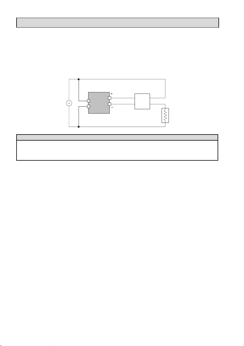
6.2 SOLID STATE RELAY (SSR) DRIVER OUTPUT........................................................................................ 8
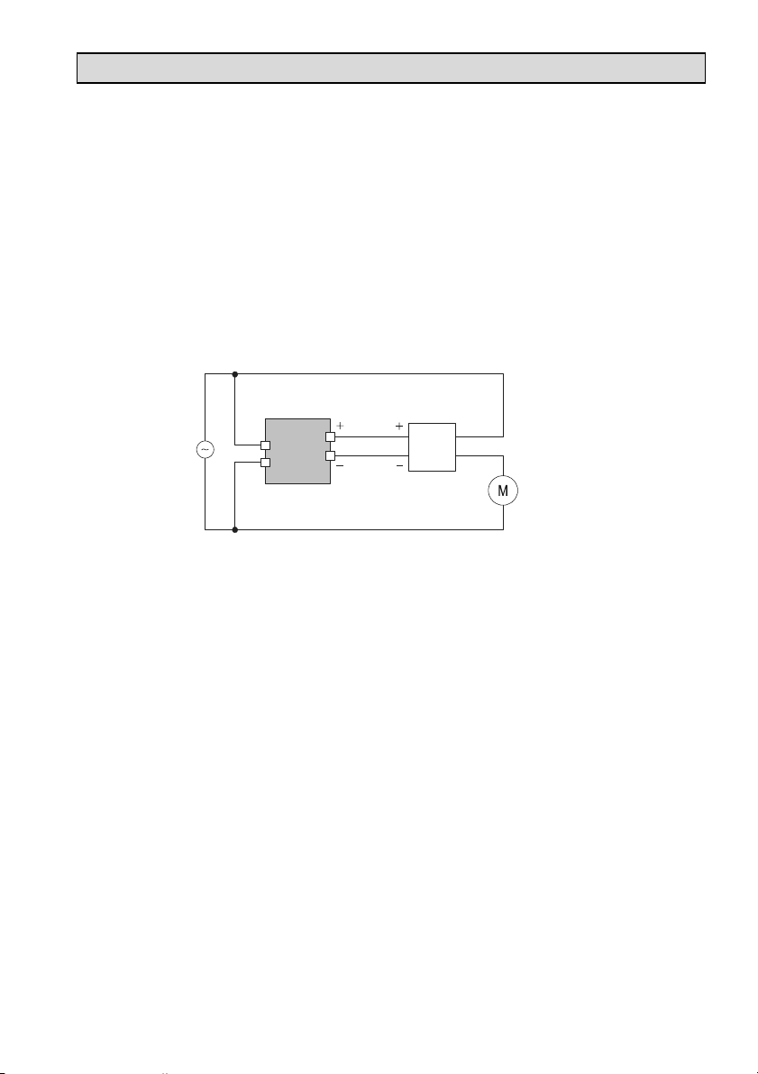
6.3 ANALOGUE (4-20 mA) OUTPUT........................................................................................................... 9
7. SETTINGS, PROGRAMMING ............................................................................................................. 10
7.1 FRONT PANEL,KEYPAD,DISPLAY...................................................................................................... 10
7.2 BASIC OPERATION............................................................................................................................ 11
7.3 ERROR MESSAGES........................................................................................................................... 11
7.4 SET VALUE (SV) ............................................................................................................................. 11
7.5 CONFIGURATION MODE.................................................................................................................... 12
7.5.1 Mode Settings...................................................................................................................... 12
7.5.2 Control Parameters ............................................................................................................. 13
8. CONTROL ALGORITHMS .................................................................................................................. 14
8.1 ON/OFF CONTROL.......................................................................................................................... 14
8.2 HEATING/COOLING (FILLING /EMPTYING)CONTROL........................................................................... 14
8.3 PROPORTIONAL (P) CONTROL ........................................................................................................... 15
8.4 PID CONTROL ................................................................................................................................. 15
9. IN- AND OUTPUT MODE SETTINGS .................................................................................................16
9.1 SELECT THE INPUT MODE ................................................................................................................. 16
9.1.1 Analogue input..................................................................................................................... 17
9.2 ALARM RELAY OUTPUT..................................................................................................................... 18
9.3 LOOP BREAK ALARM (LBA).............................................................................................................. 19
9.4 SENSOR BREAK ALARM (SBA) ......................................................................................................... 20
9.5 AUTOTUNING (AT) OPERATION.......................................................................................................... 20
9.6 DUAL PID CONTROL FUNCTION......................................................................................................... 21
9.7 RAMP FUNCTION ............................................................................................................................ 22
10. SETTING THE CONTROL PARAMETERS ...................................................................................... 23
10.1 SV-2 FUNCTION (INTERNAL SET VALUE).......................................................................................... 23
10.2 IN-B FUNCTION (INPUT CORRECTION) .............................................................................................. 23
11. FACTORY DEFAULT SETTINGS ..................................................................................................... 24
12. MAINTENANCE, REPAIR ................................................................................................................. 24
13. STORAGE CONDITIONS.................................................................................................................. 24
14. WARRANTY ...................................................................................................................................... 24

pmg4111a0600p_01
3 / 24
Thank you for choosing a NIVELCO instrument.
We are sure that you will be satisfied throughout its use!
1. GENERAL DESCRIPTION
The UNICONT PMG-411, PMG-412 and PMG-413 universal analogue PID-controllers can be used for
temperature measurement with a Pt-100 resistance thermometer or different thermocouples. The
UNICONT controllers are also suitable for processing and display the signals of field transmitters with
4-20 mA and 1-5 V DC or 0-10 V DC output. The output signal of the controller can be relay, continuous
4-20 mA process current signal or SSR-driver. The additional alarm relay provides for limit monitoring. The
unit is microprocessor based featuring auto-tuning software which is able to find the optimal P-I-D
constants automatically. The setting can be performed by the keyboard on the front panel. The large bi-
coloured display provides easy reading even from far distance. The process parameters are red, the set
values are green.
Inputs
Thermocouple
Voltage signal
PMG-400
Universal
controller
Relay
SSR driver
ON/OFF
PID
Controls
Outputs
2. ORDER CODE
UNICONT PMG–4 –
INPUT CODE OUTPUT CODE POWER SUPPLY CODE
1x Universal input 1 1x relay + 1x alarm relay 1 230 V AC 1
SSR driver + 1x alarm relay 2
4-20 mA + 1x alarm relay 3

4 / 24
pmg4111a0600p_01
3. TECHNICAL DATA
Type PMG-41-1
Resistance
thermometer
(3-wire, aut. cable
compensation)
Pt 100 (–199.9 °C...+199.9 °C or 0 °C...+500 °C)
R cable: max. 5 Ω
K (-100 °C … +1100°C); J (0°C … +800°C)
R (0°C … +1700°C); E (0°C … +800°C)
T (-200°C … +400°C); S (0°C … +1700°C)
Thermocouple
(aut. cold junction
compensation) N (0°C … +1300°C); W (0°C … +2300°C)
Voltage 1-5 V DC; 0-10 V DC
Input
Current 4-20 mA DC
Proportional band (P) 0 … 100%
Integral time (I) 0 … 3600 sec
Derivative time (D) 0 … 3600 sec
PID (auto-tuning)
Cycle time (T) 1 … 120 sec
Relay SPDT; 250 V AC, 3 A, AC1
SSR (Solid-State Relay) driver 12 V DC ±3 V (max. 30 mA)
Control
output
Output
Current 4-20 mA DC (max. load: 600 Ω)
Alarm output 1x SPST programmable relay, 250 V AC, 1 A, AC1
Setting and display accuracy ±0.3 % ±1 digit for the whole input scale or ±3 °C
PV (process value) 4 digit, 7 segment 11 mm high red LED
Display SV (set value) 4 digit, 7 segment 7 mm high green LED
Power supply 100-240 V AC 50/60 Hz, max. 5 VA
Allowable voltage range: 90% to 110% of rated voltage
Electrical connection Screw type terminals, max. wire cross-section: 0.5 mm2
Memory protection 10 years
Ingress protection Front side: IP 65, Back side: IP 20
Electrical protection Class II. Reinforced Isolation
Ambient temperature Operation: -10…+50 °C, Storage: -20…+60 °C
Ambient humidity 35 … 85% relative humidity
Dimensions 48 x 48 x 100 mm (panel cut out: 45.5+0.6 x 45.5+0.6 mm)
Weight 0.15 kg
3.1 DIMENSIONS
The unit can be mounted into a suitable
1/16DIN (48x48 mm) cut-out place.
Insertion length of the unit is 100 mm,
the additional dimensions can be seen
on the drawing.
3.2 ACCESSORIES
User’s and Programming manual
Warranty Card
Declaration of Conformity
Mounting bracket

pmg4111a0600p_01
5 / 24
4. MOUNTING
MOUNTING BRACKET
The unit can be mounted with the help of the
supplied mounting bracket to the suitable cut-
out hole. Be careful with the sealing, which
provides proper sealing from the front panel.
Suitable distances between multiple units
should be taken into consideration.
The cut-out dimensions in case of single, or
multiple units should be the following, and
width of the mounting-plate is 3 - 9 mm.
Using the optional PAM-500-0 front panel adapter the 48x48mm sized unit can be mounted to an existing
96x48mm cut-out hole. In case of using the front panel adapter, the width of the mounting-plate is
3–5 mm.
APPROPRIATE CONDITIONS OF OPERATION
The device is designed for indoor usage only and it should be protected from intense physical damage
and direct sunlight. The device cannot be applied in the following places:
environments which are exposed to strong vibration or other heavy physical impacts
flammable and dusty environments
environments above 85% relative humidity and where sudden temperature changes can happen
strongly acidic or alkaline environments
environments which are exposed to direct sunlight
environments which are exposed to strong magnetic fields or strong electrical noise
5. WIRING
5.1 INPUT SELECTION
To select the input mode it is necessary to detach the housing.
Before performing the operation always make sure that the
device is powered OFF!
Removing the housing should be carried out in two steps
shown in the drawing. First press gently the two clips on the
back side of the device, and then pull backward the inside part
of the device. Select the desired input mode with the help of
the S/W1 and the S/W2 pins and the jumpers on the circuit
board. After setting the jumpers, replace the housing to the
device.
A.) RTD INPUT AND
THERMOCOUPLE INPUT
B.) VOLTAGE INPUT
(1-5 VDC; 0-10 VDC)
C.) CURRENT INPUT
(4-20 mA)
S/W1 S/W2
S/W1 S/W2
S/W1 S/W2

6 / 24
pmg4111a0600p_01
5.2 WIRING POWER SUPPLY,INPUT/OUTPUT
PMG-411 WIRING PMG-412 WIRING
12
11
AL1 5
4
3
2
1
U
PW
OUT
10
9
8
7
6
–
+
IN1
Pt100
TC
12
11
AL1 5
4
3
2
1
U
PW
SSR
OUT
10
9
8
7
6
–
+
IN1
Pt100
TC
–
+
Relay output and Alarm output SSR driver output and Alarm output
PMG-413 WIRING MARKINGS
UPW Power supply
OUT Control output
AL1Alarm output
IN1Sensor input
12
11
AL1 5
4
3
2
1
U
PW
4…20 mA
OUT
10
9
8
7
6
–
+
IN1
Pt100
TC
–
+
IN2Control input
Analogue (4-20 mA) output and Alarm output
Note:
The power supply should be connected to the terminal via a two-pole isolating switch (preferably
located near the equipment) and an anti-surge fuse. The power is recommended to equipped with
a suitable sized, U-shaped cable lug:
Max 7.2 mm
For wiring the sensors use insulated, shielded cable as short as possible.
The input signal wires should be separated from the supply wire.

pmg4111a0600p_01
7 / 24
6. CONTROL OUTPUTS
6.1 RELAY OUTPUT
The primary function of the relay output is the realization of the PID control. In case of PID control the
relay output discontinuously turns off or on the load, thereby implements the PID control.
If the value of is ., ON/OFF control will operate. In case of ON/OFF control the relay output
continuously turns off and on the load.
For PID control or ON/OFF control applications it is recommended to use magnet switch or power relay.
Always make sure to observe the technical specifications for the relay contacts! If the relay is
overloaded, it may damage the device.
When the device is controlling main relay or magnet switch / power relay contact, the flow reverse
electromotive force from coil of power relay or magnet switch can cause interference through the supply
wire, which may result the malfunction of the device.
The mechanical lifetime of the output relay is about 107switching which should be taken into account in
any case during the design of the control system. If the relay cycle time () is set to a short value, the
life cycle of the relay is getting lower. It is recommended to choose the type with the SSR driver if the
thermal response of the system is fast and therefore the cycle time () of the relay should be set to a
very low value.
Application example:
Heater
Magnet switch
or power relay
UNICONT
A
B
Power
Note:
It is recommended to keep the power relay or magnetic switch as far as possible from the UNICONT controller.
If the wire length of ’A’ and ’B’ is too short the electromotive force occurred from the coil of the power relay or
magnetic switch may flow in the power line of the unit which may result malfunction.

8 / 24
pmg4111a0600p_01
6.2 SOLID STATE RELAY (SSR) DRIVER OUTPUT
Using the SSR driver (voltage-impulse) output the unit is suitable for high-speed controlling tasks where
the standard relay switching speed is not sufficient.
SSR driver output is suitable for driving solid state relay with 12 V DC voltage and max.30 mA load.
For the realization of high-speed control, the cycle time () of the relay is recommended to set 1 to 2
seconds.
Application example:
UNICONT
SSR
OUT SSRIN OUT
Heater
Power
Note:
The solid state relay should be selected according to the capacity of the load otherwise short circuit may occur,
which may result fire.
Usage of the SSR driver output is recommended in case of indirect heating in order to provide efficient operation.

pmg4111a0600p_01
9 / 24
6.3 ANALOGUE (4-20 mA) OUTPUT
Using of the analogue output intervening devices with current input can be controlled. As an advantageous
feature for example control valve with position control can be controlled using the analogue output.
The control output of the unit provides the current value specified by the PID parameters.
The 4 mA current value is assigned to 0 % and 20 mA is assigned to 100 %.
The maximum load of the analogue output is 600 Ω. In case of higher load the current output value will
not change proportionally to the measured value.
When current output is used the Manipulated Value (MV) is changing as analogue form and its value can
rarely be 0% or 100%. Therefore (loop break alarm) mode can not be used in case of using current
output.
When analogue output is used the OUT (control output) indicator LED on the front panel does not
indicate the status of the output.
Application example:
UNICONT
Power Analogue
output
Frequency inverter
IN OUT
Asynchronous or
synchronous motor

10 / 24
pmg4111a0600p_01
7. SETTINGS, PROGRAMMING
7.1 FRONT PANEL,KEYPAD,DISPLAY
In normal (measurement) mode the
7-segment displays show the
measured Process Value and the
Set Value. In the other modes it
shows texts and values in
accordance to the actual state of the
programming and configuration.
With the 3 arrow ( , , ) buttons
the menu-system can be handled
and programming can be performed.
CONTROL PANEL
NUMBER
NAME OPERATION
1 Process Value (PV) In normal (measurement) mode: display measured Process Value
In configuration mode: display selected setting
2 Set Value (SV) In normal (measurement) mode: display Set Value
In configuration mode: display SV or value of selected setting
3 Second SV (SV2)
indication The SV2 (green) LED lights if the internal second SV is active
4 Autotuning (AT)
indication
The AT (green) LED flashes to indicate if the
device performs the autotuning
5 Autotuning (AT)
button Press the button to enter the auto tuning mode
6 , , buttons
Press the button to move between the digits,
with / buttons the selected digit value
can be changed up or down
7 Event 1 (EV1) output
(alarm) indication The EV1 (red) LED is lit if the alarm output is active
8 Control Output (OUT)
indication The OUT (red) LED is lit if the control output is active
9 P/E button Press the button to enter the configuration mode
or return to the normal (measurement) mode

pmg4111a0600p_01
11 / 24
7.2 BASIC OPERATION
Normal
(measurement)
mode
Setting the
control
parameters
Enter the
Set Value
(SV)
Mode
Settings
3 s
3 s
3 s
Note:
The controller returns automatically from configuration mode, to normal (measurement) mode if there is no key
activity for 60 seconds.
7.3 ERROR MESSAGES
If any error occurs during the operation of the controller the display shows the following error messages:
” ” flashes on the display if input sensor is not connected or its wire is broken.
” ” flashes on the display if the measured value is lower than the low limit value in the input
range of the sensor (it is likely because the range selection is wrong).
” ” flashes on the display if the measured value is higher than the high limit value in the input
range of the sensor (it is likely because the input selection is wrong).
” ” appears on the display if the device is defective and does not operate.
7.4 SET VALUE (SV)
1. 2.
In normal (measurement) mode, press the button.
The first digit of the set value will be flashing.
Once the desired SV is entered with the arrow buttons
(, , ) press the button to accept the new
value. Then the device will return to normal
(measurement) mode.

12 / 24
pmg4111a0600p_01
7.5 CONFIGURATION MODE
7.5.1 MODE SETTINGS
Normal (measurement) mode
Mode settings
3 s3 s
+
PROGRAMMING SEQUENCE
Select the input from 19 options
Select alarm relay mode
Select alarm output mode
. Select auto-tuning mode
Select PID control algorithm
Select cooling or heating control
Select temperature measurement unit
Setting the high limit scale value of the analogue input
Setting the low limit scale value of the analogue input
Setting the decimal point (only in case of analogue input)
Turning on or off the RAMP function
Turning on or off the Key lock
In normal (measurement) mode press the and the buttons and hold for 3 seconds
to change the mode settings. If the configuration is completed press the button and
hold for 3 seconds to return to normal (measurement) mode.
The (decimal point setting) menu item appears only if analogue output is used. Also
the , , options only appears in the (input selection) list if proper
jumper settings are made as described in chapter 5.1 „Input”.

pmg4111a0600p_01
13 / 24
7.5.2 CONTROL PARAMETERS
Normal (measurement) mode
Setting the control parameters
3 s
PROGRAMMABLE CONTROL PARAMETERS
Select SV-2 (internal set value) within input range for each sensor.
SV-2 is effective if the IN2 input is active.
Set alarm relay operation value (if alarm relay mode is selected in ).
(sec)
Set the output delay time for loop break alarm (0 … 999 s)
(if is selected in )
.
(°C) .
Set the value of alarm hysteresis
(interval between ON and OFF for alarm output)
.
(%).
Set the value of Proportional band in %
If value of is set to .the unit operates in ON/OFF mode
(sec)
Set the value of Integral time in seconds
If value of is set to this function will be OFF
(sec)
Set the value of Derivative time in seconds
If value of is set to this function will be OFF
(sec)
Set the value of proportional control cycle time in seconds
In case of SSR output this value should be small, for example 2 sec.
.
(°C) .
Set the value of switching difference
in case of ON/OFF control
.
(°C) .
Set the correction value for input sensor error
Also suitable as an offset function for calibration
.
(%).
Set the value of manual reset (offset for the Proportional band) in %
(for control only)
(min)
Set the value of RAMP rising time (in case of heating)
Only when function is (enabled)
(min)
Set the value of RAMP falling time (in case of cooling)
Only when function is (enabled)
Turning OFF the key lock
When the key lock is active the configuration cannot be changed
When ON1 is selected only the mode settings and auto-tuning is locked

14 / 24
pmg4111a0600p_01
To change the control parameters, press the button and hold for 3 seconds in normal
(measurement) mode. If the configuration is completed press the button and hold for 3
seconds to return to normal (measurement) mode.
The , , , , , , , , parameters will be displayed only if the
corresponding options are selected at the operating modes.
8. CONTROL ALGORITHMS
8.1 ON/OFF CONTROL
The ON/OFF control is called two-position control because the output turns ON when the PV falls lower
then SV and the output turns OFF when the PV is higher than SV. This control method is not only for
controlling temperature it can be also used for basic control method for sequence control or level control.
The ON/OFF control is operating when the value of Proportional band () is set to .at the control
parameters.
If necessary, a programmable temperature difference () between ON and OFF can be set at the
control parameters. The setting range is 1 °C to 100 °C (or 0.1 °C and 100.0 °C). If the hysteresis width
is too small, too frequent relay switching may occur (contact bounce).
The menu item is available at the control settings only if is set to .at the control parameters.
The ON/OFF control mode should not be applied when this type of control method may cause damage to
the equipment due to the potentially too frequent ON or OFF cycle (such as cooling compressors).
Even if ON/OFF control is stable contact bounce can be occurred in the following cases: not sufficient
value, the capacity of the heating system, the response characteristics of the equipment to be
controlled, or mounting position of the sensor. These aspects should be taken into account to minimize
to possibility of contact bounce when designing the control system.
8.2 HEATING/COOLING (FILLING /EMPTYING)CONTROL
The device can control heating or cooling process but also suitable for tank level control tasks. The filling
control algorithm is the same as the heating, while the emptying control algorithm is the same as the
cooling.
The algorithm can be selected at the mode settings menu.
function: cooling, or emptying control
function: heating, or filling control
Cooling / emptying Heating / filling
t
PV
Y
t
PV
Y
PV: process value Y: intervening signal

pmg4111a0600p_01
15 / 24
8.3 PROPORTIONAL (P) CONTROL
In case of proportional control the value of the Proportional band () is not zero but the Integral time ()
and the Derivative time () are set to zero.
The Proportional band can be set within the range of 1 to 100%.
The Proportional Control will be accomplished by changing the time of the relay’s energised or
de-energised state within the cycle time. The cycle time of the relay () can be set within the range of
1 to 120 s.
Proportional range: the control range of the cycle time. Out of the proportional range the relay is always
energised or de-energised.
The value of the Proportional range: q = (%) * M, where M = measurement range.
The position of the Proportional range compared to the Set Value (SV) depends on the percentage value
set in the control parameter.
If value = 0 %, the whole range is under the SV.
If value = 50.0 %, the proportional range is symmetrical to the SV.
If value = 100 %, the proportional band is over the SV.
Process Value
()PV
Set Value
(S )V
Reduce
value
Increase
value
8.4 PID CONTROL
PID control is the most commonly used control mode because the best controlling accuracy can be
achieved with it. Similar to the Proportional (P) Control described in the previous chapter, the PID control
will be accomplished by changing the relay’s energised and de-energised states within its cycle time ().
Since the determination of the optimal P-I-D parameters are difficult and time consuming manually the
usage of the Autotuning is recommended.
Devices with analogue output (4-20 mA) PID control should be only used. Prior to start the control process
it should be determined which control characteristics (cooling or heating) is required.

16 / 24
pmg4111a0600p_01
9. IN- AND OUTPUT MODE SETTINGS
9.1 SELECT THE INPUT MODE
INPUT DISPLAY MEASUREMENT RANGE
K thermocouple K(CA)H .-100 °C … +1300 °C
K thermocouple K(CA)L .-100 °C … +999.9 °C
J thermocouple J(IC)H . 0 °C … +800 °C
J thermocouple J(IC)L . 0.0 °C … +800.0 °C
R thermocouple R(PR) 0 °C … +1700 °C
E thermocouple E(CR)H . 0 °C … +800 °C
E thermocouple E(CR)L . 0.0 °C … +800.0 °C
T thermocouple T(CC)H . -200 °C … +400 °C
T thermocouple T(CC)L . -199.9 °C … +400.0 °C
S thermocouple S(PR) 0 °C … +1700 °C
N thermocouple N(NN) 0 °C … +1300 °C
W thermocouple W(TT) 0 °C … +2300 °C
J Pt100 JPtH . 0 °C … +500 °C
J Pt100 JPtL . -199.9 °C … +199.9 °C
DIN Pt100 DPtH . 0 °C … +500 °C
DIN Pt100 DPtL . -199.9 °C … +199.9 °C
0-10 V DC -1999 …+9999
1-5 V DC -1999 …+9999
4-20 mA -1999 …+9999
Jumper setting and
scaling are needed

pmg4111a0600p_01
17 / 24
9.1.1 ANALOGUE INPUT
When using analogue input the UNICONT controller could be connected to a 4-20 mA output level
transmitter device for example.
Scaling:
In case of temperature measurement if the input is Pt100 or thermocouple, the device automatically
determines the measurement range and the position of the decimal point according to the selected type of
the input signal.
When analogue input is used (4-20 mA, 0-10 V DC, 1-5 V DC) low and high limit values should be
specified for the input measurement range. These values can be entered in the and mode
settings. In addition you can set the decimal point location at the mode setting.
Application example:
Controlled device
(e.g. pump)
Level meter
(e.g. EasyTREK SPA-380-4
Ultrasonic level transmitter)
Analogue output
(e.g. 4-20 mA)
(input mode): (4-20 mA)
(measurement range high level): (mm)
(measurement range low level): (mm)
(position of the decimal point):
Note:
For using analogue input proper jumper settings are required as described in chapter 5.1 „Input”.

18 / 24
pmg4111a0600p_01
9.2 ALARM RELAY OUTPUT
ALARM EVENTS
Loop break alarm, see the details: chapter 9.3
Sensor break alarm, see the details: chapter 9.4
No alarm output
When is 10 °C
Deviation High limit alarm
The output will be ON when the Process Value (PV)
is higher than the Set Value (SV) + .
When is 10 °C
Deviation Low limit alarm
The output will be ON when the Process Value (PV)
is lower than the Set Value (SV) - .
When is 10 °C
Deviation High/Low limit alarm
The output will be ON when the difference between
the Process Value (PV) and the Set Value (SV)
is higher or lower than .
When is 10 °C
Deviation High/Low limit reserve alarm
The output will be OFF when the difference between
the Process Value (PV) and the Set Value (SV)
is higher or lower than .
When is 110 °C
Absolute value High limit alarm
The output will be ON when the Process Value (PV)
is equal to or higher than .
When is 90 °C
Absolute value Low limit alarm
The output will be ON when the Process Value (PV)
is equal to or lower than .
The alarm output () value at the control parameters can be set within the range of 1 °C to 100 °C or
0.1 °C to 100.0 °C. The value of determines the position of the energised or de-energised state of
the alarm relay.
The ’b’ alarm relay switching hysteresis ( - time interval between ON and OFF) can be set within
the range of 1 °C to 100 °C or 0.1 °C to 100.0 °C at the control parameters.

pmg4111a0600p_01
19 / 24
ALARM RELAY OPTION SETTINGS
Symbol Operation Description
General alarm No optional alarm output, no latching
Latch function Once the alarm output turns ON, it will be continuously
activated. It can be turned OFF by selecting .
Standby sequence function
The alarm output will not turn ON the first time when PV
reaches SV. The alarm output turns ON only if PV differs
from the SV and reaches the alarm value ().
Latch & Standby sequence
function Operating latch and standby sequence function together
9.3 LOOP BREAK ALARM (LBA)
The (Loop Break Alarm) relay mode allows you to recognize an abnormal temperature of the
control system. If the temperature at the control system not changed within ±2 °C during the specified
time set in the (loop break alarm delay time) parameter then the output will be ON according to the
(alarm relay option) settings.
Example: If the Set Value (SV) is 300 °C and the Process Value (PV) is 50 °C the device controls with
100% gain. If there is no change in the temperature of the control system within the selected time
interval the unit recognizes that the heater is cut off and the output will be ON.
The value can be entered at the control parameters.
The value can be set only if the mode is selected at the alarm relay output operating
modes.
mode can be selected at the mode settings under the menu item.
The setting range of the Loop Break Alarm is 1 to 999 second.
If the thermal response of the control system is slow, should be set to sufficiently high value.
The mode operates only when the manipulated value of the controller is 0% or 100% therefore
mode cannot be used with current output.
If the output is ON in the mode, check the following:
Short-circuit or wire break at the temperature sensor
Improper operation of the controlled equipment
Improper operation of the load (heating / cooling device)
Wrong wiring
In case of sensor failure if mode is ON the output will not be active. In this case turn OFF the
unit, reconnect the sensor and then turn ON.
When mode is used and the other alarm operation functions cannot be used.

20 / 24
pmg4111a0600p_01
9.4 SENSOR BREAK ALARM (SBA)
When (Sensor Break Alarm) relay mode is used the alarm output indicates when sensor line is cut or
open. This can be indicated for example by connecting a buzzer or an emergency light to the alarm output.
mode can be selected at the mode settings under the menu item.
When mode is used and other alarm operation functions cannot be used.
9.5 AUTOTUNING (AT) OPERATION
The Autotuning function determines the optimal P-I-D constants and the cycle time based on the
automatically measured thermal characteristics and response of the control system.
The Autotuning function is recommended to use at initial time after connecting the sensor and turning
on the device.
To start the Autotuning press the button for 3 seconds or more.
When the Autotuning is started AT (green) LED will blink, after the Autotuning is finished the AT LED
turns off.
While the Autotuning function is executing it can be cancelled by pressing the button for 5 seconds
or more.
When the power turns off or the Autotuning process is cancelled manually the P-I-D constants and the
cycle time will not be saved and the previously set values remain valid.
The time constant of P-I-D selected by the Autotuning function can be manually changed at the control
parameters ().
The Autotuning operation mode (there are 2 different options) can be selected at the menu item.
When mode is selected (factory default setting) Autotuning is executed at the entered Set Value
(SV), when mode is selected Autotuning is executed at the 70% of the entered Set Value (SV).
It is necessary to execute the Autotuning periodically since the thermal characteristics of the control
system can be changed when the controller is used continuously for a long time.
mode mode
A
utotunin
g
time
°C
SV
Time (t)
°C
Time (t)
SV
70 %
A
utotunin
g
time
Table of contents
Other NIVELCO Controllers manuals