Niviuk KODE P User manual

KODE P
User’s manual

2
NIVIUK GLIDERS & AIR GAMES SL C/ DEL TER 6, NAVE D 17165 LA CELLERA DE TER - GIRONA - SPAIN
KODE P
YOUR MOUNTAIN PARTNER
WELCOME
We wish to welcome you to our team and thank you for your trust in
choosing a Niviuk wing.
We would like to share the enthusiasm with which we created this wing
and the importance and care we took in the design and manufacture of
this new model. All this in order to offer maximum pleasure on every ight
with a Niviuk glider.
The Kode P is an accessible and light mountain wing to accompany you
on your hike & y adventures.
We are condent you will enjoy ying this wing and will soon discover the
meaning of our motto:
“The importance of small details”.
This is the user manual and we recommend you read it carefully.
USER MANUAL
This manual provides the necessary information on the main
characteristics of your new paraglider.
Whilst it provides information on the wing, it cannot be viewed as an
instructional handbook and does not offer the training required to y this
type of paraglider.
Training can only be undertaken at a certied paragliding school and each
country has its own system of licensing.
Only the aeronautical authorities of respective countries can determine
pilot competence.
The information in this manual is provided in order to warn you against
adverse ying situations and potential dangers.
Equally, we would like to remind you that it is important to carefully read all
the contents of your new KODE P manual.
Misuse of this equipment could lead to severe or irreversible injuries
to the pilot, even death. The manufacturers and dealers cannot be held
responsible for misuse of the paraglider. It is the responsibility of the pilot
to ensure the equipment is used correctly.

3
INDEX
WELCOME 2
USER MANUAL 2
1.1 WHO IS IT DESIGNED FOR? 4
1.2 CERTIFICATION 4
1.3 IN-FLIGHT BEHAVIOR 5
1.4 CONSTRUCTION, MATERIALS 5
1.5 ELEMENTS, COMPONENTS 6
2. UNPACKING AND ASSEMBLY 7
2.1 CHOOSING THE RIGHT LOCATION 7
2.2 PROCEDURE 7
2.3 CONNECTING THE HARNESS 7
2.4 HARNESS TYPE 7
2.5 SPEED-BAR 7
2.6 INSPECTION AND WING INFLATION ON
THE GROUND 9
2.7 ADJUSTING THE BRAKES 9
3. THE FIRST FLIGHT 9
3.1 CHOOSING THE RIGHT LOCATION 9
3.2 PREPARATION 9
3.3 FLIGHT PLAN 9
3.4 PRE-FLIGHT CHECK 10
3.5 WING INFLATION, CONTROL AND
TAKEOFF 10
3.6 LANDING 10
3.7 PACKING 10
4. IN FLIGHT 10
4.1 FLYING IN TURBULENCE 11
4.2 POSSIBLE CONFIGURATIONS 11
4.3 ACCELERATED FLIGHT 13
4.4 FLYING WITHOUT BRAKE LINES 13
4.5 LINE KNOT(S) IN FLIGHT 13
5. LOSING ALTITUDE 13
5.1 BIG EARS 13
5.2 B-LINE STALL 14
5.3 SPIRAL DIVE 14
5.4 SLOW DESCENT TECHNIQUE 14
6. SPECIAL METHODS 15
6.1 TOWING 15
6.2 ACROBATIC FLIGHT 15
7. CARE AND MAINTENANCE 15
7.1 MAINTENANCE 15
7.2 STORAGE 16
7.3 CHECKS AND INSPECTIONS 16
7.4 REPAIRS 16
8. SAFETY AND RESPONSIBILITY 16
9. GUARANTEE 17
10. ANNEXES 18
10.1 TECHNICAL DATA 19
10.2 MATERIALS DESCRIPTION 20
10.3 RISER PLAN 21
10.4 LINE PLAN 22
10.5 LINE LENGTHS KODE P SIZE 16
10.6 LINE LENGTHS KODE P SIZE 18
10.7 LINE LENGTHS KODE P SIZE 20
10.8 LINE LENGTHS KODE P SIZE 22
10.9 LINE LENGTHS KODE P SIZE 24
10.10 LINE LENGTHS KODE P SIZE 26
10.11 CERTIFICATION

4
1. CHARACTERISTICS
1.1 WHO IS IT DESIGNED FOR?
The Kode P is an accessible and light mountain wing to accompany you
on your hike & y adventures.
Enjoy pleasant and more progressive handling in the classic sizes (20, 22,
24, 26) and more direct and dynamic ying in the smaller sizes (16 and
18), which are more suitable for experienced hike & y pilots.
Its versatility facilitates a multitude of adventures. The wing permits ying
in thermals and strong winds without having to compromise on safety
and comfort. In addition, its lightness and ease of take off on all types of
terrain will enhance hike & y adventures.
1.2 CERTIFICATION
The KODE P has been submitted for the European EN and LTF
certication.
All certication tests were conducted by the Air Turquoise testing centre in
Switzerland.
All sizes passed the load, shock and ight tests.
The wing passed the sustained load test with an 8G load factor.
It also passed the shock loading test with 800 daN of force.
The ight test resulted in the following certication for all KODE P sizes:
EN A
LTF A
Size 16 of the KODE P has been certied as:
EN B
LTF B
If the wing is loaded above the maximum certied take off weight for sizes
16 and 18, the certication changes as follows:
EN C
LTF C
We recommend that only pilots who are familiar with gliders of this
certication or above y this paraglider.
Only the aeronautical authorities of respective countries can determine
pilot competence.
We recommend pilots read the certication ight test report carefully,
especially the comments of the test pilot. The report contains all the
necessary information on how the paraglider reacts during each of the
tested manoeuvres.
It is important to point out that the appropriate response to each adverse
manoeuvre can vary from size to size; even within the same size at
maximum or minimum load, the behaviour and reactions of the wing may
vary.
-Description of ight characteristics of EN A paragliders:
Paragliders with maximum passive safety and extremely forgiving ight
characteristics. Gliders with good collapse resistance in normal ight.
-Description of the skills required by the pilot to y an EN A wing:
Designed for all pilots, including pilots under instruction.
-Description of ight characteristics of EN B paragliders:
Paragliders with a high degree of passive safety and very forgiving ight
characteristics. Gliders with high collapse resistance outside normal ight.
-Description of the skills required by the pilot to y an EN B wing:
Designed for all pilots, at any level of qualication.

5
-Description of ight characteristics of EN C paragliders:
Paragliders with moderate passive safety, potentially dynamic reactions
to turbulence and pilot errors. The recovery to normal ight may require
precise interventions by the pilot.
-Description of the skills required by the pilot to y an EN C wing:
Designed for pilots familiar with recovery techniques, who y actively and
understand the implications of ying a paraglider with reduced passive
safety.
For further information on the ight test and the corresponding
certication number, please see the nal pages of this manual or visit the
product page download section at www.niviuk.com .
1.3 IN-FLIGHT BEHAVIOUR
Niviuk developed this wing by adopting very specic goals: to improve
performance, excellent handling and to facilitate more control for the pilot.
To increase performance while maintaining the highest level of safety.
To ensure that the wing transmits the maximum feedback in an
understandable and comfortable way so that the pilot can focus on
piloting and enjoying the ight. And, with active piloting, make the most of
all favourable conditions.
The glider is very solid in all aspects of ight. The glide is smooth, even
when fully accelerated. When gliding, it has an excellent sink rate and
the prole remains stable. Improved turn precision means handling
is less physical. Inating the wing is much easier and gentler, without
overshooting.
Flying this wing is very intuitive, with clear, usable feedback about the
surrounding airmass. It responds to the pilot’s inputs effectively and even
in thermic and turbulent conditions, it remains stable and solid.
The KODE P ies efciently. It enters thermals with sufcient speed to
centre in the lift and climb progressively. The handling is progressive and
effective for even more ying pleasure under a meticulously designed
wing of extraordinary quality.
It is lightweight, even lighter in ight and easy to pilot, with outstanding
turbulence buffering and an amazing range of speed for incredible glides.
1.4 CONSTRUCTION, MATERIALS
The KODE P features all the technological innovations in design and
construction used in our manufacturing facilities. It is built with the
most careful selection of current materials, technology and accessories
available, to improve pilot comfort whilst increasing safety and
performance.
In the design of all Niviuk products the team aims to ensure development
and continuous improvement. The technologies developed in recent years
have allowed us to develop more evolved and higher performance wings.
In short, better and better gliders. It is in this context that we would like to
introduce the technologies featured in this new model.
RAM Air Intake - this system is characterised by the arrangement of the
air inlets, to ensure optimal maintenance of internal pressure. Thanks to
this design, we were able to reduce their size, while maintaining the same
air ow at all angles to improve laminar ow. Thus more consistency
across the whole speed range and better performance without
compromising on safety.
Titanium Technology (TNT) - a revolutionary technique using titanium.
Using Nitinol in the internal construction provides a more uniform prole
and reduces the weight to gain efciency in ight. Nitinol provides the
highest level of protection against deformation, heat or breaks.

6
Structural Leading Edge (SLE) - provides more rigidity and stability along
the span of leading edge but also allows full exibility along the both
the vertical and horizontal axis. A reduction in the amount of Mylar, in
comparison to previous proles, has resulted in less weight which makes
it easier to inate the wing.
3D Pattern Cut Optimization (3DP) - an optimised process to cut the
fabric panels to ensure the perfect form of the leading edge. Creating
separate panels for each of the sections at the front of the wing means
the sail fabric is tauter and crease-free. During the cutting, the optimal
orientation of the fabric section is selected, depending on its nal location.
If the fabric pattern is properly aligned with the axes of load, it suffers less
deformation after repeated use, to the long-term benet of the leading
edge.
3D Leading Edge (3DL) - adding an extra reinforced seam to the leading
edge helps to ensure more consistency and volume in the prole. This
provides a more efcient 3D contour.
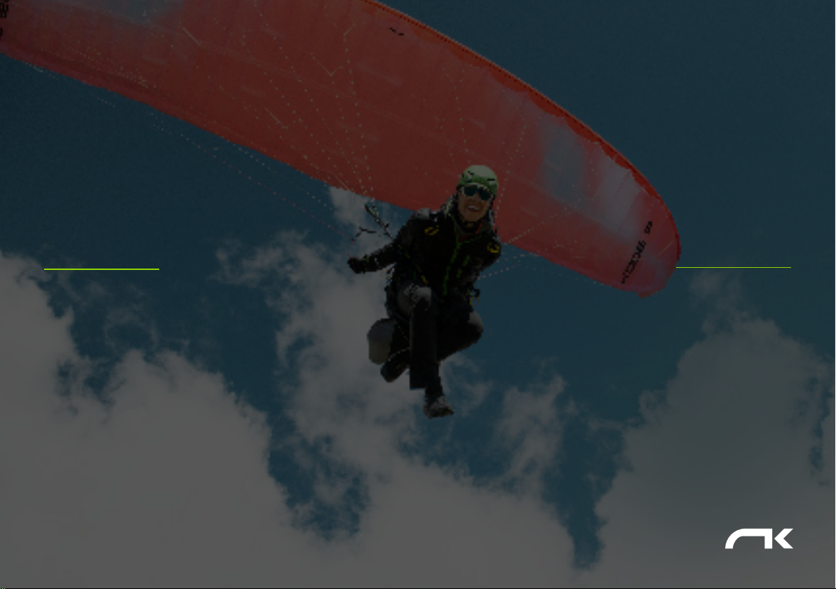
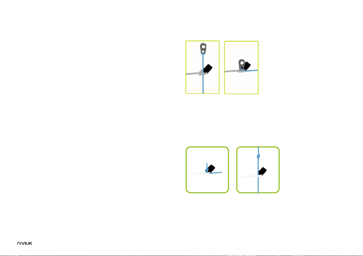
Interlock System (IKS) - is an ultralight connection system specially
designed for mountain and lightweight equipment. With less weight than
the traditional delta maillon it is nevertheless much stronger.
The use of these technologies is a big technological leap forward in
building wings and a big improvement in ight comfort.
For the construction process of the KODE P we use the same criteria,
quality controls and manufacturing processes as in the rest of our range.
From Olivier’s computer to the nished cut piece of fabric, not even
the minutest of error is permitted; the cutting of each of the assembly
elements that make up the paraglider is carried out one by one, through
rigorous and extremely meticulous work. The same meticulous system
is used for the subsequent marking and numbering of each piece, thus
avoiding possible errors in this very delicate process.
The jigsaw puzzle assembly method makes it easier to organise, saves
resources and provides excellent quality control. All Niviuk gliders go
through an extremely rigorous and detailed nal inspection. For example,
the canopy is cut and assembled through an automated process that
follows a very strict order where there is no margin for error.
Finally each wing is individually inspected.
The same fabric has been used as in the rest of the range, ensuring its
guaranteed lightness, strength and durability without fading.
The main lines are made from and the mid and gallery lines are made from
unsheathed Aramid.
The line diameter has been calculated depending on the workload and
aims to achieve the required best performance with the least drag.
The lines are semi-automatically cut to length and all the sewing is
completed under the supervision of our specialists.
Once the nal assembly of the canopy is concluded, every line is checked
and measured.
Each glider is packed according to the most advanced material
maintenance and conservation guidelines..
Niviuk gliders are made of premium materials that meet the requirements
of performance, durability and certication that the current market
demands.
Information about the various materials used can be viewed in the nal
pages of this manual.
1.5 ELEMENTS/COMPONENTS
The KODE P is delivered with a series of accessories that will greatly
assist in the maintenance of the paraglider:
- A Kargo bag. This bag is large enough to hold all equipment comfortably
and with plenty of space.
- An inner bag to protect the wing during storage and transport.
- An adjustable compression strap to compress the inner bag and reduce
its volume.
- A riser protector, which will prevent metal parts from coming into contact

7
with the cloth during storage.
- A repair kit with self-adhesive Ripstop tape and spare O-rings to protect
the maillons.
2. UNPACKING AND ASSEMBLY
2.1 CHOOSING THE RIGHT LOCATION
We recommend unpacking and assembling the wing on a training hill or a
at clear area without too much wind and free of obstacles. It will assist in
carrying out all the recommended steps required to check and inate the
KODE P.
We recommend that a qualied instructor or a local Niviuk dealer is
present to supervise the entire procedure, as only they can address any
doubts in a safe and professional way.
2.2 PROCEDURE
Take the glider out of the rucksack, open and unfold it on the ground
with the lines positioned on the undersurface, oriented in the direction
of ination. Check the cloth and lines are undamaged and all maillons
connecting the lines and risers are locked. Identify, and if necessary
untangle, the A, B, C, and the brake lines and corresponding risers. Make
sure that there are no knots.
2.3 CONNECTING THE HARNESS
The KODE P risers are colour-coded.
- right: green
- left: red
This colour-coding makes it easier to connect the wing to the correct side
and helps prevent pre-ight errors.
Correctly connect the risers to the attachment points so that the risers
and lines are correctly ordered and free of twists. Check that the IKS or
carabiners are properly fastened and securely locked.
2.4 HARNESS TYPE
The KODE P can be own with all current harness types. If the chosen
harness has an adjustable chest strap, we recommend setting this to the
distance recommended during certication, which will vary depending on
the size of the harness. See the certication report.
Care should be taken with the chest strap setting, as the distance of the
chest strap setting will affect the handling of the glider. If the chest strap
is too wide, it allows greater feedback but this carries the risk of affecting
the stability of the wing.
If the chest strap is set too tightly, the wing feels more solid, but there is a
loss of feedback and a risk of twisting in the case of a violent asymmetric
collapse.
2.5 CONNECTING THE SPEED-BAR
TThe speed-bar is a means of temporary acceleration by changing the
airow over the prole. The speed system comes pre-installed on the
risers and is not modiable as it conforms to the measurements and limits
stipulated during certication.
The KODE P includes a speed system with maximum travel depending
on its size (see Full speed-bar). The speed system is engaged when the
pilot pushes the speed-bar (not included as standard with this glider
model) with their feet. The pilot must t and install the speed-bar and
connect it to the risers (see 2.5.1: Speed system assembly).
The speed system uses an action/reaction system. Released, the speed-
bar is set to neutral. When the bar is pushed using the feet, the wing
accelerates. The speed can be regulated by varying the pressure on the
bar. Once the pressure on the bar is released, the speed system returns to
the neutral setting.

8
The speed system is efcient, sensitive and precise. The pilot can use the
system whenever they want during the ight. In the neutral position, the
glider will y at standard speed and glide. Using full speed-bar, the wing
will y at maximum speed, but the glide will be adversely affected.
•Released speed-bar: the A, B, C, -risers are aligned.
•Full speed-bar: the difference between the A - C-risers becomes:
Size 16 – 100 mm
Size 18 – 100 mm
Size 20 – 160 mm
Size 22 – 160 mm
Size 24 – 160 mm
Size 26 – 160 mm
PLEASE NOTE
The use of the speed system results in changes to the speed but also the
reactions of the wing. For more information, please see the certication
report.
2.5.1 Speed system assembly
The speed-bar consists of the bar that the pilot pushes with their feet, as
well as the two cords that connect it to the speed system components on
the risers. Once you have chosen the type of speed-bar you prefer, you
must install it. Some considerations:
•The pilot should use the type of speed-bar they consider appropriate,
depending on the type of harness, personal preferences, etc.
•The speed-bar is detachable to facilitate its connection and/or
disconnection to the risers as well as subsequent adjustment.
•To connect it to the harness, please follow the instructions of the harness
manufacturer. The majority of harnesses have a speed system pre-
installed.
•The standard connection of the speed-bar to the speed system is via
Brummel hooks, where two slots in the hooks are interlocked, making
their connection/disconnection easy. However, any connection system
that is safe may be used.
Plume (P) models - please note
The P models were designed with the idea of saving weight across the
entire equipment. To achieve this, Niviuk decided to deliver the wings
without the classic Brummel hooks and opting for a kite-style knotting
system. This system offers the same efciency and safety as the classic
Brummel hooks, but with much less weight.
1.Make a knot in the speed-bar cord and we pass this through the cord
connections on the risers.
2.Apply tension to both sides until the knots are locked tightly in the riser
connections.

9
The system or procedure for connecting the kite knot is exactly the same
as the Brummel hooks and can be used in other systems or connection
elements.
2.5.2 Changing the riser cords
In spite of the speed system having pulleys with bearings to reduce
friction to a minimum, the frequency with which the speed-bar is used
causes the cords to wear and they may need to be replaced.
In all Niviuk gliders the speed system cords on the risers are completely
removable and easily replaceable. The pilot can use the Brummel hooks,
not use them, remove them, use another type of connector, etc. It is
even possible to x the speed-bar cords directly to the speed system
on the risers. This last option makes the connection/disconnection more
laborious, but means the cord has maximum travel without obstructions
or restrictions which is very useful for some models of harnesses.
2.6 INSPECTION AND WING INFLATION ON THE GROUND
After a thorough pre-ight inspection and the weather conditions deemed
favourable for ying, inate your KODE P as many times as necessary to
familiarise yourself with its behaviour. Inating the KODE P is easy and
should not require a great deal of physical effort. Inate the wing with a
little pressure from the body using the harness. This may be assisted by
using the A-lines. Do not pull on them; just accompany the natural rising
movement of the wing. Once the wing is inated to the overhead position,
appropriate control with the brakes will be sufcient to hold it there.
2.7 ADJUSTING THE BRAKES
The length of the main brake lines is adjusted at the factory and they
conform to the length stipulated during certication. However, the length
can be changed to adapt to the pilot’s ying style. It is advisable to y
with the original setting for a period of time to get used to the actual
behaviour of the KODE P. In case it is necessary to modify the brake
length, loosen the knot, slide the line through the brake handle to the
desired point and re-tighten the knot rmly. Only qualied personnel
should carry out this adjustment. You must ensure that the modication
does not affect the trailing edge and SLOW the glider down without pilot
input. Both brake lines should be symmetrical. We recommend using a
clove hitch or bowline knot.
When changing the brake length, it is necessary to check that they do
not engage when the speed-bar is used. When we accelerate, the glider
rotates over the C-riser and the trailing edge elevates. It is important
to check that the brake is adjusted to take into consideration this extra
distance during acceleration. With this prole deformation there is a risk of
generating turbulence and causing a frontal or asymmetric collapse.
3. THE FIRST FLIGHT
3.1 CHOOSING THE RIGHT LOCATION
For the rst ight we recommend going to your usual ying area or a
training hill and that a qualied instructor is present and supervising the
entire procedure.
3.2 PREPARATION
Repeat the procedures detailed in chapter 2 UNPACKING AND
ASSEMBLY to prepare your equipment.
3.3 FLIGHT PLAN
Planning a ight before taking off to avoid possible problems later is
always a good idea.

10
3.4 PRE-FLIGHT CHECK
Once ready, but before taking off, conduct another equipment
inspection. Conduct a thorough visual check of your gear with the wing
fully open, the lines untangled and properly laid out on the ground to
ensure that all is in working order. Be certain the weather conditions are
suited to your ying skill level.
3.5 WING INFLATION, CONTROL AND TAKE OFF
Smoothly and progressively inate the wing. The KODE P inates easily
and does not require additional input. The wing does not have the
tendency to overy the pilot. It is a straight forward exercise leaving
enough time for the pilot to decide whether to accelerate and take off or
not.
If the wind permits, we recommend a reverse launch, as this allows a
better visual inspection of the wing during ination. In “strong” winds, the
KODE P is especially easy to control using this launch technique. Winds
of 25 to 30 km/h are considered strong for paragliding.
Correctly setting up the wing on the ground before take off is vitally
important. To ensure a clean launch, choose an appropriate location
facing the wind. Position the paraglider in a crescent conguration to
facilitate ination.
3.6 LANDING
The KODE P lands excellently, it converts the wing speed into lift at your
demand, allowing an enormous margin of error. Wrapping the brake lines
around your hand to get greater braking efciency is not necessary.
3.7 PACKING
The KODE P has a complex leading edge, manufactured using a variety
of different materials and it must be packed carefully. A correct folding
method is very important to extend the useful life of the paraglider.
It should be concertina-packed, with the leading edge reinforcements at
and the exible rods stacked one on top of the other. This method will
keep the prole in its original shape without compromising its prole or
performance. Ensure the reinforcements are not bent or folded. The wing
should not be folded too tightly to avoid damage to the cloth and/or lines.
At Niviuk we have designed the NKare Bag, a bag designed to assist you
with rapid packing which helps maintain the integrity of the leading edge
and keeps its internal structures in perfect condition.
The NKare Bag guides you through the folding process, allowing you to
concertina-pack the wing with each rod on top of the other and then fold
the wing as required. This folding system ensures that both the fabric and
the reinforcements of the internal structure are kept in perfect condition.
4. IN FLIGHT
We recommend that you read the certication test report. The report
contains all the necessary information on how the KODE P reacts during
each of the tested manoeuvres.
It is important to point out that the appropriate response to an adverse
incidence can vary from size to size; even within the same size at
maximum or minimum load the behaviour and reactions of the wing may
vary.
Having the knowledge that the testing house provides through the test
report is fundamental to learning how to deal with possible situations.
We recommend learning to y this wing under the guidance of a qualied
instructor.

11
4.1 FLYING IN TURBULENCE
The KODE P has an excellent prole to buffer turbulence. It is very stable
in all conditions and has excellent passive ight reactions, which makes it
very safe in turbulent conditions.
All paragliders must be piloted for the prevailing conditions and the pilot is
the ultimate safety factor.
We recommend active ying in turbulent conditions, always taking
measures to maintain control of the wing, preventing it from collapsing
and restoring the speed required by the wing after each correction.
Do not correct the glider (braking) for too long in case this provokes
a stall. If you have to take corrective action, make the input then re-
establish the correct ying speed.
4.2 POSSIBLE CONFIGURATIONS
We recommend learning to y this wing under the guidance of a qualied
instructor. The pilot must adapt their use of the brakes depending on the
wing-loading and avoid over-steering.
It is important to point out that the appropriate response to an adverse
incidence can vary from size to size; even within the same size at
maximum or minimum load the behaviour and reactions of the
wing may vary.
In the test report, you will nd all the necessary information on how to
handle your new wing during each of the tested manoeuvres. Having this
information is crucial to know how to react during incidents in real ight,
so you can deal with these situations as safely as possible.
Asymmetric collapse
In spite of the KODE P’s prole stability, strong turbulent air may cause
the wing to collapse asymmetrically, especially if the pilot is unable to y
actively and prevent the collapse. In this case the glider conveys a loss of
pressure through the brake lines and the harness. To prevent the collapse
from happening, pull the brake handle corresponding to the affected side
of the wing. It will increase the incidence of the wing (angle of attack). If
the collapse does happen, the KODE P will not react violently, the turning
tendency is gradual and easily controlled. Weight-shift toward the open,
ying side (the opposite side of the collapse) to keep the wing ying
straight, while applying light brake pressure to that side if necessary.
Normally, the collapsed side of the wing should then recover and reopen
by itself. If it does not, then pull the brake handle on the collapsed side
decisively and quickly all the way (100%) down. You may have to repeat
this pumping action to force the re-opening of the deated glider side. Do
not over-brake or slow down the ying side of the wing (control the turn).
Once the collapsed side is open make sure you return to the
default ying speed.
Frontal collapse
Due to the KODE P’s design, in normal ying conditions frontal collapses
are unlikely to take place. The wing’s prole has great buffering abilities
when dealing with extreme incidence changes. A frontal collapse may
occur in strong turbulent conditions, entering or exiting powerful thermals
or when lacking experience using the speed-bar without adapting to the
prevailing conditions. Frontal collapses usually re-inate without the glider
turning, but a symmetrically applied quick braking action with a quick
deep pump of both brakes will accelerate the re-ination if necessary.
Release the brake lines immediately to return to default glider air speed.
Negative spin
A negative spin does not conform to the KODE P’s normal ight
behaviour. Certain circumstances however, may provoke a negative spin
(such as trying to turn when ying at very low air speed whilst applying

12
a lot of brake). It is not easy to give any specic recommendation about
this situation other than quickly restoring the wing’s default air speed
and angle of attack by progressively reducing the tension on the brake
lines. The normal wing reaction will be to have a lateral surge on the re-
accelerated side with a rotation not greater than 360º before returning to
default air speed.
Parachutal stall
The possibility of entering or remaining in a parachutal stall have been
eliminated from the KODE P .
A parachutal stall is virtually impossible with this wing. If it did enter into
a parachutal stall, the wing loses forward motion, becomes unstable
and there is a lack of pressure on the brake lines, although the canopy
appears to be fully inated. To regain normal air speed, release brake line
tension symmetrically and manually push on the A-risers or weight-shift
your body to any side WITHOUT PULLING ON THE BRAKE LINES.
Deep Stall
The possibility of the KODE P stalling during normal ight is very unlikely.
It could only happen if the pilot ies at a very low air speed, whilst over-
steering or performing dangerous manoeuvres in turbulent air.
To induce a deep stall, the wing has to be slowed down to its minimum air
speed by symmetrically pulling the brake lines all the way (100%) down
until the stall point is reached and held there for several seconds. The
glider will rst pitch rearward and then reposition itself overhead, rocking
slightly, depending on how the manoeuvre was done.
When entering a stall, remain clear-headed and ease off the brake lines
until reaching the half-way point of the total the brake travel. The wing
will then surge violently forward and could reach a point below the pilot. It
is most important to maintain brake pressure for a few seconds until the
glider has returned to its default overhead ying position.
To resume normal ight conditions, progressively and symmetrically
release the brake line tension to regain air speed. When the wing reaches
the overhead position, the brakes must be fully released. The wing will
then surge forward to regain full air speed. Do not brake excessively at
this moment as the wing needs to accelerate to pull away from the stall
conguration. If you have to control a possible frontal collapse, briey
pull both brake handles down to bring the wing back up and release
them immediately while the glider is still in transition to reposition itself
overhead.
Cravat
A cravat may happen after an asymmetric collapse, when the end of the
wing is trapped between the lines. Depending on the nature of the tangle,
this situation could rapidly cause the wing to spin. In the same way as
controlling an asymmetric collapse, control the turn/spin by applying
tension on the opposite brake and weight-shift opposite to the turn. Then
locate the stabilo line (attached to the wingtip) trapped between the other
lines. This line has a different colour and is located on the outside position
of the B-riser.
Pull on this line until it is taught, as it should help undo the cravat. If
ineffective, y down to the nearest possible landing spot, controlling the
direction with both weight-shift and the use of the brake opposite to the
tangled side. Be cautious when attempting to undo a tangle while ying
near terrain or other paragliders; it may not be possible to continue on the
intended ight path.
Over-controlling
Most ying problems are caused by poor decisions or wrong pilot
input, which then escalate into a cascade of unwanted and unpredicted
incidents. We should note that the wrong inputs can lead to loss of control
of the glider. The KODE P was designed to recover by itself in most cases.
Do not try to over-correct it!
Generally speaking, the reactions of the wing, which are caused by too
much input, are due to the length of time the pilot continues to over–

13
control the wing. You have to allow the glider to re-establish normal ying
speed and attitude after any type of incident
4.3 ACCELERATED FLIGHT
The KODE P prole was designed for stable ight throughout its entire
speed range. The speed-bar can be used in strong winds or signicant
sink.
When accelerating the wing, the prole becomes more sensitive to
turbulence and closer to a possible frontal collapse. If a loss in internal
wing pressure is felt, tension on the speed-bar should be reduced to a
minimum and a slight pull on the brake lines is recommended to increase
the wing’s angle of attack. Always remember to re-establish the correct air
speed after any correction.
It is NOT recommended to accelerate near obstacles or in very turbulent
conditions. If necessary, constantly adjust the movements and pressure
on the speed-bar whilst doing the same to the brake lines. This means
active ying during accelerated ight.
4.4 FLYING WITHOUT BRAKE LINES
If, for any reason at all, the KODE P’s brake lines become disabled in
ight, it will become necessary to pilot the wing with the C-risers and
weight-shifting until landing. These risers steer easily because they are
not under much tension, however you will need to be careful and not
handle them too heavily in case this causes a stall or negative spin. The
wing must be own at full speed during the landing approach, and the
C-risers will have to be pulled symmetrically all the way down shortly
before contact with the ground. This braking method is not as effective as
using the brake lines, and hence the wing will land with a higher
ground speed.
4.5 LINE KNOT(S) IN FLIGHT
The best way to avoid knots and tangles is to thoroughly inspect the lines
as part of a systematic pre-ight check. If a knot is spotted during the
take off phase, immediately abort the launch sequence and stop.
If inadvertently taking off with a knotted line, the glider drift will need to
be compensated by weight-shifting to the opposite side of the wing and
applying a slight brake pull to that side. Gently pull the brake line to see
if the knot can be undone or try to locate the problem line. Beware of
trying to clear or untangle a knotted line in ight when close to the terrain.
If the knot is too tight and cannot be undone, carefully and safely y to
the nearest landing zone. Be careful: do not pull too hard on the brake
handles because there will be an increased risk of stalling the wing or
entering a negative spin. Before attempting to clear a knot, make sure
there are no other pilots ying in the vicinity.
5. LOSING ALTITUDE
Knowledge of different descent techniques could become vital in
certain situations. The most suitable descent method will depend on the
particular situation.
We recommend learning these maneuvers under the guidance of a
qualied instructor.
5.1 BIG EARS
Big ears is a moderate descent technique, able to increase the sink rate
to –3 or –4 m/s and reduces the ground speed by 3 to 5 km/h. The angle
of attack and effective wing-loading will also increase due to the smaller
surface area of the wing.
To perform the ‘Big ears’ manoeuvre, take the outermost line on each
A-riser (line 4a1 in size 16 y 18 and specically the A’ line in sizes 20,
22, 24 and 26) and simultaneously, smoothly pull them outward and
downward. The wingtips will fold in.

14
To re-establish forward speed and the correct angle of attack, accelerate
once the ears are pulled.
Keep the ears pulled in until you have lost the desired altitude.
Let go of the lines to re-inate the tips automatically. If they do not, try
pulling one brake then the other. We recommend inating the wingtips
asymmetrically, without major change to the angle of attack, especially
when ying near the ground or ying in turbulence.
5.2 B-LINE STALL
When carrying out this manoeuvre, the wing stops ying, loses all
horizontal speed and the pilot is no longer in control of the paraglider.
The airow over the prole is interrupted and the wing enters a situation
similar to parachuting.
To enter this manoeuvre, the B-risers are gripped below the maillons and
symmetrically pulled down together (approx. 20-30 cm) and maintained in
that position.
Initiating the manoeuvre is physically demanding because it can take
some strength to pull the risers down until the wing is deformed. After
this, the physical effort is less. Continue to hold the risers in position.
Once the wing is deformed, its horizontal speed will drop to 0 km/h;
vertical descending speed increases to –6 to –8 m/s, depending on the
conditions and how the manoeuvre is performed.
To exit the manoeuvre, simultaneously release both risers. The wing will
then slightly surge forward and automatically return to normal ight. It is
better to let go of the lines quickly rather than slowly.
This is an easy descent technique to perform, but remember that the wing
will stop ying, will lose all forward horizontal speed, and its reactions will
change markedly when compared to a normal ight conguration.
5.3 SPIRAL DIVE
This is a more effective way to rapidly lose altitude. Beware that the wing
will experience and be subjected to a tremendous amount of descending
and rotating speed (g-force), which can cause a loss of orientation and
consciousness (blackout). This manoeuvre must therefore be done
gradually to increase one’s capacity to resist the g-force exerted on the
body and to be able to perform the manoeuver safely.
To enter a spiral dive, rst weight-shift and pull the brake handle located
on the inner side of the turn. The intensity of the turn can be controlled by
braking slightly using the outer brake handle.
A paraglider ying at its maximum rotating speed can reach -20 m/s, or
the equivalent of a 70 km/h vertical descent, and will stabilise in a spiral
dive from 15 m/s onwards. Good enough reasons to familiarise yourself
with the manoeuvre and understand how to exit it.
To exit this manoeuvre, the inner brake handle (down side of the turn)
must be released progressively while the pilot must also weight-shift and
lean towards the opposite side. Stop when the wing begins to exit from
the spiral.
The exit should be performed gradually and smoothly so that the changes
in pressure and speed can be noted.
When exiting the spiral, the glider may briey oscillate and dive sideways,
depending on how the manoeuvre was carried out.
Practise these manoeuvres at sufcient altitude and with moderation.
5.4 SLOW DESCENT TECHNIQUE
This technique allows a very gradual descent without straining the wing
or taxing the pilot. Glide normally while searching for descending air and
begin to turn as if climbing in a thermal, but with the intention to sink.

15
Common sense has to be used to avoid dangerous areas of rotor when
looking for descending air. Safety rst!
6. SPECIAL METHODS
6.1 TOWING
The KODE P does not experience any problem whilst being towed. Only
qualied winch personnel should handle the certied equipment to carry
out this operation. The wing must be inated in the same way as during a
normal hill take off.
It is important to use the brakes to correct the ight path alignment,
especially at the beginning of the tow. Since the wing is subject to a slow
airspeed and with a high positive angle of attack, any course corrections
must be made with a high degree of feel and delicacy, in order to avoid a
stall.
6.2 ACROBATIC FLIGHT
Although the KODE P was tested by expert acrobatic pilots in extreme
situations, it was NOT designed for this type of ying. We do NOT
recommend using this glider for aerobatics.
We consider extreme or acrobatic ights to be any form of piloting
different than standard ights. Learning aerobatic/acrobatic manoeuvres
should be conducted under the supervision of qualied instructors within
a school environment and over water with all safety/rescue elements in
place. When performing extreme manoeuvres, you will subject both the
glider and your body to centrifugal forces that can reach up to 4 or 5 g,
wearing out the material much faster than with normal ight.
7. CARE AND MAINTENANCE
7.1 MAINTENANCE
Careful maintenance of your equipment will ensure continued top
performance. Independently of annual inspections, we advise active care
of the equipment.
A pre-ight check is obligatory before each ight.
If you have any unforeseen incidents which may affect the areas where
the equipment is most susceptible to damage, you should check and act
accordingly.
At Niviuk we are rmly committed to make technology accessible to all
pilots. For this reason all our wings are tted with the latest innovations.
Thanks to our innovative technologies, the wing has more safety and
performance, but this means being more careful with the material.
A hard impact or dragging the leading edge against a hard surface can
damage the sail cloth. All incidents involving the leading edge should be
reviewed.
If a Nitinol rod is damaged, they are easily replaceable.
The fabric and the lines do not need to be washed. If they become
dirty, clean them with a soft damp cloth, using only water. Do not use
detergents or other chemicals.
If your wing is wet from contact with water, place it in a dry area, air it and
keep it away from direct sunlight.
Direct sunlight may damage the wing’s materials and cause premature
deterioration. Before launch or after landing, do not leave the wing
exposed to the sun. Pack it and stow it away in its backpack.
If ying in a sandy environment, and sand has accumulated inside the
wing, remove it before packing it away. The apertures at the wingtips

1616
facilitate easy removal of objects from the trailing edge.
If your wing is wet from contact with salt water, immerse it in fresh water
and dry it away from direct sunlight.
7.2 STORAGE
Keep your equipment in the in a cool, dry place away from solvents, fuels
or oils.
Do not leave the gear inside a car boot, as cars left in the sun can become
very hot. A rucksack can reach temperatures up to 60ºC.
Weight should not be laid on top of the equipment.
It is very important to pack the wing correctly before storage.
In case of long-term storage it is advisable, if possible, that the wing is
not compressed and it should be stored loosely without direct contact
with the ground. Humidity and heating can have an adverse effect on the
equipment.
7.3 CHECKS AND INSPECTIONS
Inspections
In accordance with its certication, the KODE P must be periodically
serviced. An inspection must be scheduled every 100 ying hours or
every two years, whichever comes rst.
We strongly recommend that any repairs should be done in a specialist
repair shop by qualied personnel.
This will guarantee the airworthiness and continued certication of your
KODE P.
A thorough pre-ight check must be performed before every ight.
Checking unsheathed lines
The KODE P is tted with unsheathed lines whose durability is within the
standards of unsheathed lines. Their strength is guaranteed and their
resistance to UV is one of the highest in this type of lines.
7.4 REPAIRS
If the case of small tears, you can temporarily repair these by using the
tape included in the repair kit, as long as no stitching is required to mend
the fabric.
Any repair should be done in a specialist repair shop by qualied
personnel.
Damaged lines must be repaired or exchanged immediately.
Please refer to the line plan at the end of this manual.
We recommend any inspection or repair is performed by a Niviuk
professional in our ofcial workshop:
https://niviuk.com/niviuk-service-form
Any modication of the glider made in an unauthorised workshop will
invalidate the guarantee of the product. Niviuk cannot be held responsible
for any issues or damage resulting from modications or repairs carried
out by unqualied professionals or who are not approved by the
manufacturer.
8. SAFETY AND RESPONSIBILITY
It is well known that free-ying with a paraglider is considered a high-risk
sport, where safety depends on the person who is practicing it.
Incorrect use of this equipment may cause severe, life-changing injuries
to the pilot, or even death. Manufacturers and dealers cannot be held
responsible for your decisions, actions or accidents that may result from

17
participating in this sport.
You must not use this equipment if you have not been properly trained
to use it. Do not take advice or accept any informal training from anyone
who is not properly qualied as a ight instructor.
9. GUARANTEE
The equipment and components are covered by a 2-year warranty against
any manufacturing defect.
The warranty does not cover misuse of the equipment.

ANNEXES
10.1 TECHNICAL DATA
10.2 MATERIALS DESCRIPTION
10.3 RISER PLAN
10.4 LINE PLAN
18

19
16 18 20 22 24 26
34 34 34 34 34 34
4,75 4,75 4,75 4,75 4,75 4,75
3,83 3,83 3,83 3,83 3,83 3,83
M2 16 18 20 22 24 26,5
M2 14,35 16,05 17,61 19,37 21,13 23,33
M8,72 9,25 9,75 10,22 10,68 11,22
M2,26 2,39 2,52 2,65 2,76 2,9
M218 231 243 255 267 281
3/3/2 3/3/2 2+1/3/2 2+1/3/2 2+1/3/2 2+1/3/2
3+1 A/B/C A/B/C A+A'/B/C A+A'/B/C A+A'/B/C A+A'/B/C
MM 100 100 160 160 160 160
KG 1,8 1,98 2,15 2,3 2,6 2,8
KG -50-70 60-85 65-90 70-95 90-115
KG 45-70 50-80 ----
KG 70-90 70-100 ----
Kode P
CELLS NUMBER
ASPECT RATIO
FLAT
PROJECTED
FLAT
AREA PROJECTED
SPAN FLAT
CORD MAXIMUM
TOTAL
LINES MAIN
NUMBER
RISERS ACCELERATOR
GLIDER WEIGHT
WEIGHT RANGE EN/LTF A
WEIGHT RANGE EN/LTF B
WEIGHT RANGE EN/LTF C
10. ANNEXES
10.1 TECHNICAL DATA

CANOPY FABRIC CODE SUPPLIER
UPPER SURFACE D20 / N10 DOMINICO TEX CO (KOREA)
BOTTOM SURFACE N10 DOMINICO TEX CO (KOREA)
PROFILES 70000 E91 PORCHER IND (FRANCE)
2044 FM DOMINICO TEX CO (KOREA)
DIAGONALS 70000 E91 PORCHER IND (FRANCE)
TENSION BANDS 2044 32 FM DOMINICO TEX CO (KOREA)
LOOPS LKI - 12 KOLON IND. (KOREA)
REIFORCEMENT LOOPS 30D ST DOMINICO TEX CO (KOREA)
TRAILING EDGE REIFOR-
CEMENT
MYLAR D-P (GERMANY)
RIBS REIFORCEMNET LTN-0.5/0.8 STICK SPORTWARE CO.CHINA
THREAD SERAFIL 60 AMAN (GERMANY)
SUSPENSION LINES FABRIC CODE SUPPLIER
UPPER CASCADES DC - 60 LIROS GMHB (GERMANY)
UPPER CASCADES A-8000/U 50 EDELRID (GERMANY)
UPPER CASCADES A-8000/U 70 EDELRID (GERMANY)
MIDDLE CASCADES A-8000/U 70 EDELRID (GERMANY)
MIDDLE CASCADES A-8000/U 90 EDELRID (GERMANY)
MIDDLE CASCADES A-8000/U 130 EDELRID (GERMANY)
MAIN A-8000/U 130 EDELRID (GERMANY)
MAIN A-8000/U 190 EDELRID (GERMANY)
MAIN A-8000/U 230 EDELRID (GERMANY)
MAIN BREAK TARAX-200 EDELRID (GERMANY)
RISERS FABRIC CODE SUPPLIER
MATERIAL 3455 / CSAR7 COUSIN (FRANCE)
COLOR INDICATOR 210D TECNI SANGLES (FRANCE)
THREAD V138 COATS (ENGLAND)
PULLEYS RF25109 RONSTAN (AUSTRALIA)
10.2 MATERIALS DESCRIPTION
20
Table of contents
Other Niviuk Aircraft manuals

Niviuk
Niviuk ICEPEAK 7 PRO-MODEL User manual

Niviuk
Niviuk R-BUS 2 User manual

Niviuk
Niviuk Kougar-2 User manual

Niviuk
Niviuk ROLLER 2 User manual

Niviuk
Niviuk DOBERMANN User manual

Niviuk
Niviuk KOUGAR 3 User manual

Niviuk
Niviuk KOYOT 3 User manual

Niviuk
Niviuk ARROW P Series User manual

Niviuk
Niviuk R-BUS User manual

Niviuk
Niviuk TAKOO 2 User manual

Niviuk
Niviuk HOOK 5 P User manual

Niviuk
Niviuk PEAK 6 User manual

Niviuk
Niviuk HOOK 6 User manual

Niviuk
Niviuk SKIN 2 P User manual

Niviuk
Niviuk ICEPEAK 8 User manual

Niviuk
Niviuk Hook 5 User manual

Niviuk
Niviuk SKIN 3 P User manual

Niviuk
Niviuk ROLLER User manual

Niviuk
Niviuk MAKAN User manual

Niviuk
Niviuk Takoo 4 User manual