manuals.online logo
Brands
  1. Home
  2. •
  3. Brands
  4. •
  5. Nixie Clock
  6. •
  7. Clock
  8. •
  9. Nixie Clock Frank 3 Configuration guide

Nixie Clock Frank 3 Configuration guide

Other Nixie Clock Clock manuals
Nixie Clock Divergence Meter User manual

Nixie Clock

Nixie Clock Divergence Meter User manual

Nixie Clock IN-14 All-In-One Instructions for use

Nixie Clock

Nixie Clock IN-14 All-In-One Instructions for use

Nixie Clock Gemini Two User manual

Nixie Clock

Nixie Clock Gemini Two User manual

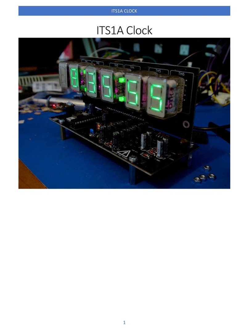
Nixie Clock ITS1A User manual

Nixie Clock

Nixie Clock ITS1A User manual

Nixie Clock Thyratron ITS1-A/B User manual

Nixie Clock

Nixie Clock Thyratron ITS1-A/B User manual

Nixie Clock DA-2000 User manual

Nixie Clock

Nixie Clock DA-2000 User manual

Nixie Clock IN-14 All-In-One User manual

Nixie Clock

Nixie Clock IN-14 All-In-One User manual

Nixie Clock IN-8-2 Installation instructions

Nixie Clock

Nixie Clock IN-8-2 Installation instructions

Nixie Clock IV-11 User manual

Nixie Clock

Nixie Clock IV-11 User manual

Nixie Clock QS18-12 User manual

Nixie Clock

Nixie Clock QS18-12 User manual

Nixie Clock IN-14 All-In-One Specification sheet

Nixie Clock

Nixie Clock IN-14 All-In-One Specification sheet

Nixie Clock IN-18 Blue Dream User manual

Nixie Clock

Nixie Clock IN-18 Blue Dream User manual

Nixie Clock RSH27 User manual

Nixie Clock

Nixie Clock RSH27 User manual

Nixie Clock MOD-SIX Use and care manual

Nixie Clock

Nixie Clock MOD-SIX Use and care manual

Nixie Clock IV-22 User manual

Nixie Clock

Nixie Clock IV-22 User manual

Nixie Clock CHRONOTRONIX V400 User manual
Nixie Clock

Nixie Clock CHRONOTRONIX V400 User manual

Nixie Clock Wemos Series User manual

Nixie Clock

Nixie Clock Wemos Series User manual

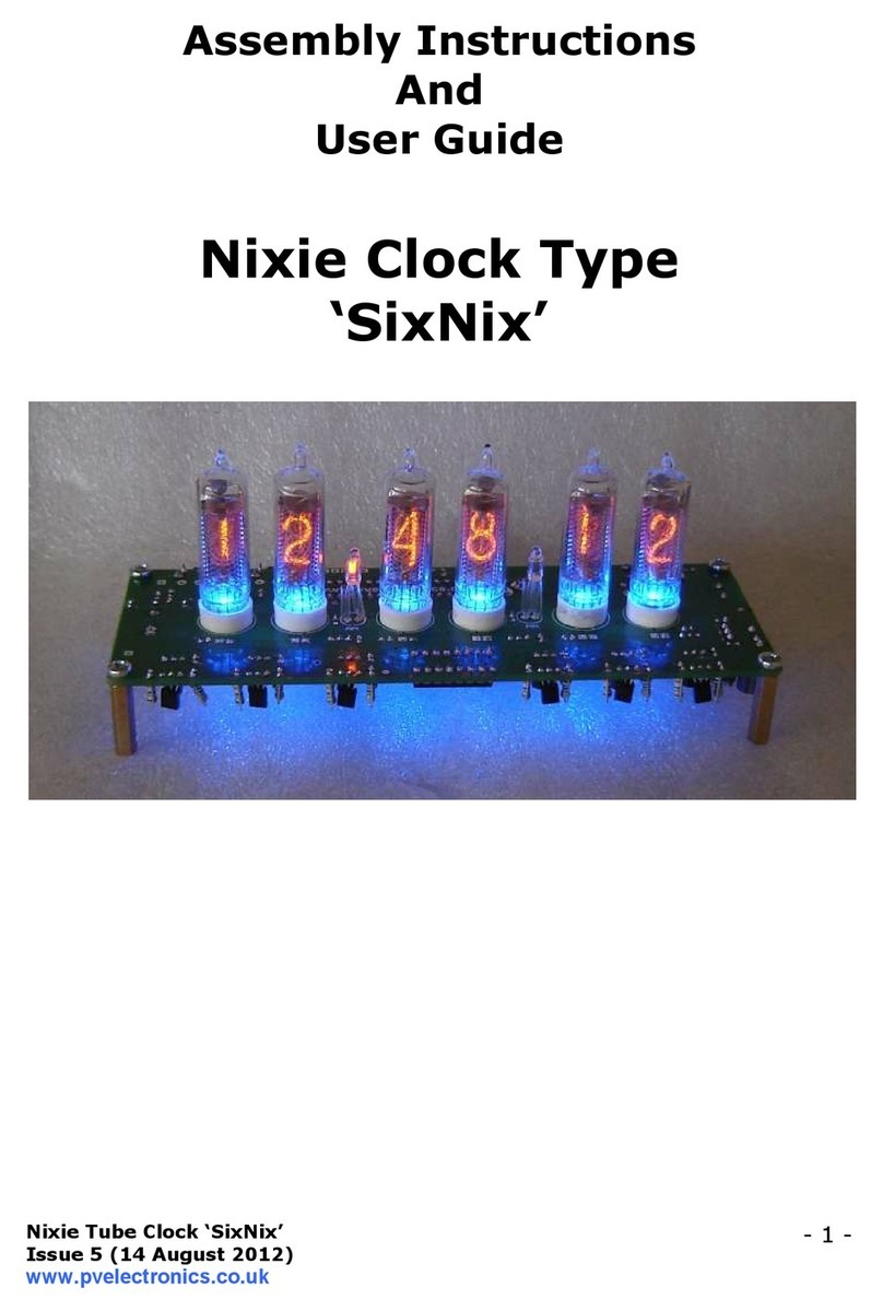
Nixie Clock SixNix Configuration guide

Nixie Clock

Nixie Clock SixNix Configuration guide

Nixie Clock IN-14 All-In-One User manual
Nixie Clock

Nixie Clock IN-14 All-In-One User manual

Nixie Clock IN-16 User manual

Nixie Clock

Nixie Clock IN-16 User manual

Nixie Clock IN-17 Installation instructions

Nixie Clock

Nixie Clock IN-17 Installation instructions

Nixie Clock 6xIN-12 User manual

Nixie Clock

Nixie Clock 6xIN-12 User manual

Popular Clock manuals by other brands

Sapling NTP 7000 Series installation manual
Sapling

Sapling NTP 7000 Series installation manual

Amano MTX-30F Installation & operation guide

Amano

Amano MTX-30F Installation & operation guide

La Crosse Technology BBB86118v3 Setup guide

La Crosse Technology

La Crosse Technology BBB86118v3 Setup guide

BEARWARE 304474 manual

BEARWARE

BEARWARE 304474 manual

LS & S RTC103U instruction manual

LS & S

LS & S RTC103U instruction manual
BitGen Technologies LED Walk/Don't Walk Clock user manual
BitGen Technologies

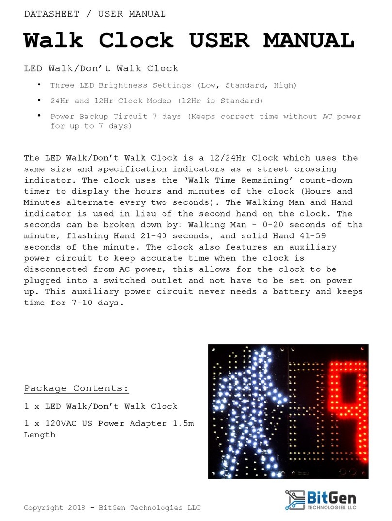
BitGen Technologies LED Walk/Don't Walk Clock user manual
Heathkit GC-1005 Assembly manual

Heathkit

Heathkit GC-1005 Assembly manual

Oregon Scientific PRYSMA RMR221P manual

Oregon Scientific

Oregon Scientific PRYSMA RMR221P manual

Andrew O'Malley DOTKLOK Assembly instructions

Andrew O'Malley

Andrew O'Malley DOTKLOK Assembly instructions

La Crosse Technology WS-8256-AL user manual

La Crosse Technology

La Crosse Technology WS-8256-AL user manual

Mini Gadgets MCPro user manual

Mini Gadgets

Mini Gadgets MCPro user manual

Casio TMR-200 user guide

Casio

Casio TMR-200 user guide

Progetti KALIMERO Directions

Progetti

Progetti KALIMERO Directions

Progetti ILTEMPOSTRINGE Directions

Progetti

Progetti ILTEMPOSTRINGE Directions

La Crosse Technology WT-3141b Quick setup instructions

La Crosse Technology

La Crosse Technology WT-3141b Quick setup instructions

IKEA ROTBLÖTA manual

IKEA

IKEA ROTBLÖTA manual

U-Line Н-2811 instructions

U-Line

U-Line Н-2811 instructions

Silicon Laboratories SI5324 manual

Silicon Laboratories

Silicon Laboratories SI5324 manual

manuals.online logo
manuals.online logoBrands
  • About & Mission
  • Contact us
  • Privacy Policy
  • Terms and Conditions

Copyright 2025 Manuals.Online. All Rights Reserved.

Nixie Tube Clock ‘Frank 3’
Issue 4 (30 Sept 2011)
www.pvelectronics.co.uk
-
1
-
ssembly Instructions
nd
User Guide
Nixie Clock Type
‘Frank 3’
2011 Edition
Nixie Tube Clock ‘Frank 3’
Issue 4 (30 Sept 2011)
www.pvelectronics.co.uk
-
2
-
REVISION HISTORY
Issue
Number
Date Reason for Issue
4 30 Sept 2011 Typing errors corrected
3 14 Sept 2011 Corrected resistor values
2 21 July 2011 Corrections to LED bending procedure
1 11 July 2011 ew document
Nixie Tube Clock ‘Frank 3’
Issue 4 (30 Sept 2011)
www.pvelectronics.co.uk
-
3
-
1. INTRODUCTION
1.1 bout the clock
ixie clock type ‘Frank 3’ is a compact design with all components and
tubes mounted on a single PCB. The efficient use of board space is
achieved by using a multiplex design to drive the display tubes. Only a
single high-voltage binary-to-decimal decoder IC (74141) is required,
and each tube is switched on in sequence very quickly to give the illusion
that all the tubes are actually lit.
The larger tubes for hours and minutes are type I -12 with a digit height
of 18mm. The smaller tubes for the seconds are type I -17 with a digit
height of 9mm. These tubes are Russian in origin and were produced
during the 1980’s, when the technology was at it’s most advanced. It is
expected that the tubes will last for very many years and should not need
replacing.
The optional wooden case and hardware pack (rear cover, screws),
supplied rough-machined, can be finished to give a very attractive clock
for everyday living spaces. The quality of the final finish will reflect the
time and care that is taken to finish the wood with successively finer
grades of sandpaper. Alternatively, you may wish to design your own
enclosure for the clock.
1.2 Clock Features
ixie clock type ‘Frank 3’ has the following features:
- Hours, Minutes and Seconds display
- 12 or 24 hour modes
- Date display in either DD.MM.YY or MM.DD.YY format
- Alarm, with programmable snooze period
- Programmable date display each minute
- Attractive LED tube lighting
- Uses a Quartz Crystal Oscillator as the timebase
- Optional DCF/WWVB/ MSF/GPS synchronisation with status LED
- Supercapacitor backup. Keeps time during short power outages
- Simple time setting using two buttons
- Programmable leading zero blanking
- Five programmable neon colon settings (Flashing AM/PM indication,
illuminated AM/PM indication, both flashing, both on, both off)
- Seconds can be reset to zero to precisely the set time
- Programmable night mode - blanked or dimmed display to save tubes
or prevent sleep disturbance
- Separate modes for colon neons during night mode
- Standard or fading change of digits
- ‘Slot Machine’ Cathode poisoning prevention routine
- All user preferences stored to non-volatile memory
Nixie Tube Clock ‘Frank 3’
Issue 4 (30 Sept 2011)
www.pvelectronics.co.uk
-
4
-
1.3 S FETY
D NGER: The clock pcb includes a switched-mode voltage booster
circuit. This generates nominally 170 Volts DC, but is capable of
generating up to 300 Volts before adjustment. Assembly may only be
undertaken by individuals who are suitably qualified and experienced in
electronics assembly, and are familiar with safe procedures for working
with high voltages. If in doubt, refer to a suitably qualified engineer
before proceeding.
The voltages generated by this circuit can give a potentially
LETH L ELECTRIC SHOCK.
DISCLAIMER: This product is supplied as a kit of parts, intended only for
suitably qualified electronic engineers, who are suitably qualified and
experienced in electronics assembly, and are familiar with safe
procedures for working with high voltages. The supplier, his agents or
associates accept no liability for any damage, injury or death arising from
the use of this kit of parts.
This is not a finished product, and the person assembling the kit is
responsible for ensuring that the finished product complies with any
applicable local regulations governing electrical equipment, eg. UL, CE,
VDE.
Nixie Tube Clock ‘Frank 3’
Issue 4 (30 Sept 2011)
www.pvelectronics.co.uk
-
5
-
2. TOOLS ND EQUIPMENT REQUIRED
2.1 Tools required to assemble the PCB
The following tools will be required to assemble the PCB:
- Soldering iron with a small tip (1-2 mm)
- Wire cutters (TIP: A small pair of nail clippers works very well for this
function)
- Wire strippers (TIP: A small pair of scissors is quite suitable)
- Multimeter
- Small flat screwdriver for adjusting the high voltage supply
2.2 Materials you will need
Solder – lead / tin solder is preferred. Lead free solder, as now required
to be used in commercial products in Europe, has a much higher melting
point and can be very hard to work with.
Desoldering wick (braid) can be useful if you accidentally create solder
bridges between adjacent solder joints.
2.3 Other items you will need
The clock kit does not include a power adapter. This is because the kit is
sold to many countries around the world, each with very different
household mains outlet socket types. It is more efficient for the user to
buy a suitable adapter locally. This saves shipping a heavy adapter with
the kit, and also the extra costs of managing stocks of many varied
power adapters. If you are using a WWVB, DCF or MSF receiver avoid
cheap Chinese switching power supplies, as they can cause interference
problems.
The type of power adapter can be obtained at very low cost. The
following type of adapter should be obtained and used with the kit:
Output 12V DC
Minimum power output capability of 250 mA
Output plug: 2.1mm pin, centre positive.
Nixie Tube Clock ‘Frank 3’
Issue 4 (30 Sept 2011)
www.pvelectronics.co.uk
-
6
-
3. LIST OF COMPONENTS
3.1 Table of components
Circuit Designation
Part Description
Resistors
R1 390K, ¼ Watt
R2 4K3, ¼ Watt
R3 100R, ¼ Watt
R4 4K3, ¼ Watt
R5
–
R7
560R, ¼ Watt
R8 - R10 10K, ¼ Watt
R11 560R, ¼ Watt
R12, R13 10K, ¼ Watt
R14 - R17 2K7, ¼ Watt
R18, R19 5K6, ¼ Watt
R20
–
R25
390K, ¼ Watt
R26 – R33 10K, ¼ Watt
R34, R35 390K, ¼ Watt
R36 – R41 560R, ¼ Watt
Capacitors
C1 470uF, 16-25V, Electrolytic
C2 100uF, 16-25V, Electrolytic
C3 1uF, 250V, Electrolytic
C4 33pF Ceramic
C5 33pF Ceramic
C6 0.1F
C7 100nF Ceramic
Transistors
Q1 IRF730 or IRF630 MOSFET
Q2, Q3 MPSA42 P
Q4 – Q9 MPSA92 P P
Q10 – Q18 MPSA42 P
Diodes
D1 – D3 1 5817 or 1 5819
D4 UF4004
D5 ot installed
D6 – D8 1 4148
D9 5mm Green LED
D10 5mm Orange LED
D11 – D16 3mm Blue LED
Integrated Circuits
IC1 7805 5V voltage regulator
IC2 PIC16F1936 8-bit microcontroller
IC3 74141 / K155 ixie driver
Miscellaneous
L1 100uH – 220uH inductor
E1, E2 4mm wire ended neon lamp
SW1, SW2, SW3 Miniature vertical push button
VR1 1K Potentiometer
IC Socket 28 Way IC socket for IC2
Nixie Tube Clock ‘Frank 3’
Issue 4 (30 Sept 2011)
www.pvelectronics.co.uk
-
7
-
J1 2.1mm Chassis power socket
GPS / RFT 6 way mini DI PCB socket
LS1 Piezo sounder
FUSE 500mA fuse
SKT1-44 1mm PCB Sockets
Insulation Clear insulation for neons
X1 32.768KHz watch crystal
The resistors used in the kit are 1% tolerance metal film. They are
marked with 4 coloured bands to identify the value. However it is
sometimes unclear in which direction the bands should be read.
Therefore, we recommend that the resistors be identified with a
multimeter.
Nixie Tube Clock ‘Frank 3’
Issue 4 (30 Sept 2011)
www.pvelectronics.co.uk
-
8
-
3.2 Parts list / Packing sheet
Part Description Quantity
Resistors
100R, ¼ Watt 1
560R, ¼ Watt 10
2K7, ¼ Watt 4
4K3, ¼ Watt 2
5K6, ¼ Watt 2
10K, ¼ Watt 13
390K, ¼ Watt 9
Capacitors
470uF, 16-25V, Electrolytic 1
100uF, 16-25V, Electrolytic 1
1uF, 250V, Electrolytic 1
100nF, Ceramic 1
33pF, Ceramic 2
0.1F 1
Transistors
IRF730 or IRF630 MOSFET
1
MPSA92 P P 6
MPSA42 P 11
Diodes
1 581x 3
UF4004 fast recovery diode 1
1 4148 3
5mm Green LED 1
5mm Orange LED 1
3mm Blue LED 6
Integrated Circuits
7805 5V voltage regulator 1
PIC16Fxxxx 8-bit microcontroller 1
74141 / K155 ixie driver 1
Miscellaneous
100uH – 470uH inductor 1
4mm wire ended neon lamp 2
Miniature vertical push button 3
1K potentiometer 1
28 way IC Socket for IC2 1
2.1mm Chassis power socket 1
6 way mini DI PCB socket 1
Piezo sounder 1
500mA fuse 1
6 cm clear insulation 1
32.768KHz watch crystal 1
It is recommended that the kit is checked against the list above, to
ensure all parts are present before commencing assembly. Don’t be
alarmed if there are some extra components, as some component
bags are shared between different kit types.
Nixie Tube Clock ‘Frank 3’
Issue 4 (30 Sept 2011)
www.pvelectronics.co.uk
-
9
-
4. SSEMBLY OF THE PCB
4.1 1mm Sockets For Nixie Tubes
There are 44 individual sockets that need to be soldered in. The
best method is a follows. Place all sockets into the holes, noting
that for each tube there is one hole that has no socket as show
below. When all sockets have been placed, place a flat and hard
object over the top of the sockets, and turn the PCB over so you
can solder from the underside. Be sure to insert the sockets FROM
the component side of the PCB – the side with the white
component markings. The photo below shows the component side
of the PCB after all the sockets have been inserted and soldered in.
4.2 Capacitor C7
Mount C7 on the same side of the PCB as the white cross-hatched
markings for Q1 and IC1. See below.
Clip the leads on the main component side very short, as the IC
socket for IC2 will need to fit over the trimmed leads.
Nixie Tube Clock ‘Frank 3’
Issue 4 (30 Sept 2011)
www.pvelectronics.co.uk
-
10
-
4.3 Low Voltage Power components:
J1, FUSE, D1-D3, IC1, C1, C2
Start by installing D1-D3. Align the white band on the components
with the band marked on the PCB.
Continue to mount C1, C2, J1 and FUSE ote that C1 and C2 are
polarised. The longer lead goes in the hole marked (+). J1, the DC
power input connector and IC1 are mounted on the opposite side of
the PCB to the other components in this step.
See the picture below. IC1 is mounted vertically at this stage - do
not bend it over the marked area yet.