manuals.online logo
Brands
  1. Home
  2. •
  3. Brands
  4. •
  5. Nixie Clock
  6. •
  7. Clock
  8. •
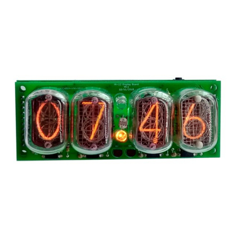
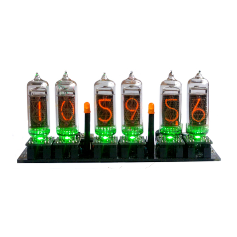
  9. Nixie Clock IN-16 User manual

Nixie Clock IN-16 User manual

Other Nixie Clock Clock manuals

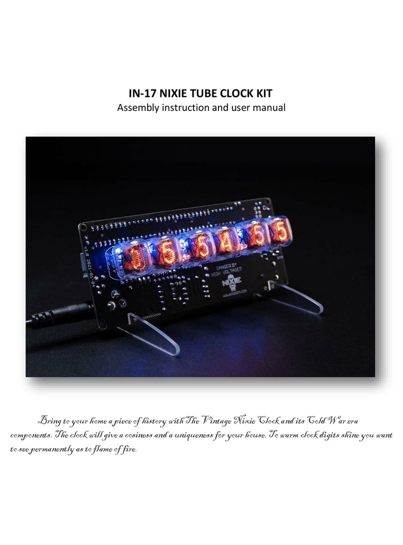
Nixie Clock IN-17 Installation instructions

Nixie Clock

Nixie Clock IN-17 Installation instructions

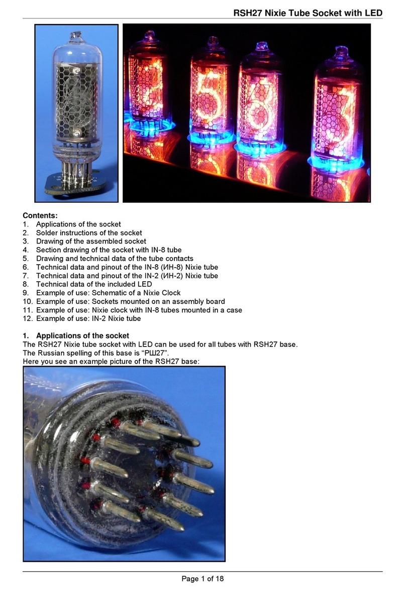
Nixie Clock RSH27 User manual

Nixie Clock

Nixie Clock RSH27 User manual

Nixie Clock MOD-SIX Use and care manual

Nixie Clock

Nixie Clock MOD-SIX Use and care manual

Nixie Clock CHRONOTRONIX V400 User manual

Nixie Clock

Nixie Clock CHRONOTRONIX V400 User manual

Nixie Clock QS18-12 User manual

Nixie Clock

Nixie Clock QS18-12 User manual

Nixie Clock 6xIN-12 User manual

Nixie Clock

Nixie Clock 6xIN-12 User manual

Nixie Clock IN-14 All-In-One Specification sheet

Nixie Clock

Nixie Clock IN-14 All-In-One Specification sheet

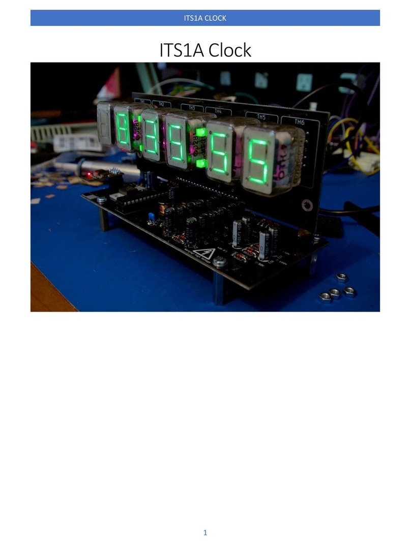
Nixie Clock Thyratron ITS1-A/B User manual

Nixie Clock

Nixie Clock Thyratron ITS1-A/B User manual

Nixie Clock IN-14 All-In-One User manual

Nixie Clock

Nixie Clock IN-14 All-In-One User manual

Nixie Clock IV-11 User manual

Nixie Clock

Nixie Clock IV-11 User manual

Nixie Clock Gemini Two User manual

Nixie Clock

Nixie Clock Gemini Two User manual

Nixie Clock SixNix Configuration guide

Nixie Clock

Nixie Clock SixNix Configuration guide

Nixie Clock IN-18 Blue Dream User manual
Nixie Clock

Nixie Clock IN-18 Blue Dream User manual

Nixie Clock IN-8-2 Installation instructions

Nixie Clock

Nixie Clock IN-8-2 Installation instructions

Nixie Clock Divergence Meter User manual

Nixie Clock

Nixie Clock Divergence Meter User manual

Nixie Clock Wemos Series User manual

Nixie Clock

Nixie Clock Wemos Series User manual

Nixie Clock ITS1A User manual

Nixie Clock

Nixie Clock ITS1A User manual
Nixie Clock DA-2000 User manual

Nixie Clock

Nixie Clock DA-2000 User manual
Nixie Clock IN-14 All-In-One Instructions for use
Nixie Clock

Nixie Clock IN-14 All-In-One Instructions for use

Nixie Clock IN-14 All-In-One User manual

Nixie Clock

Nixie Clock IN-14 All-In-One User manual

Nixie Clock Frank 3 Configuration guide

Nixie Clock

Nixie Clock Frank 3 Configuration guide

Nixie Clock IV-22 User manual

Nixie Clock

Nixie Clock IV-22 User manual

Popular Clock manuals by other brands
Sapling NTP 7000 Series installation manual
Sapling

Sapling NTP 7000 Series installation manual

Amano MTX-30F Installation & operation guide

Amano

Amano MTX-30F Installation & operation guide

La Crosse Technology BBB86118v3 Setup guide
La Crosse Technology

La Crosse Technology BBB86118v3 Setup guide

BEARWARE 304474 manual

BEARWARE

BEARWARE 304474 manual

LS & S RTC103U instruction manual

LS & S

LS & S RTC103U instruction manual
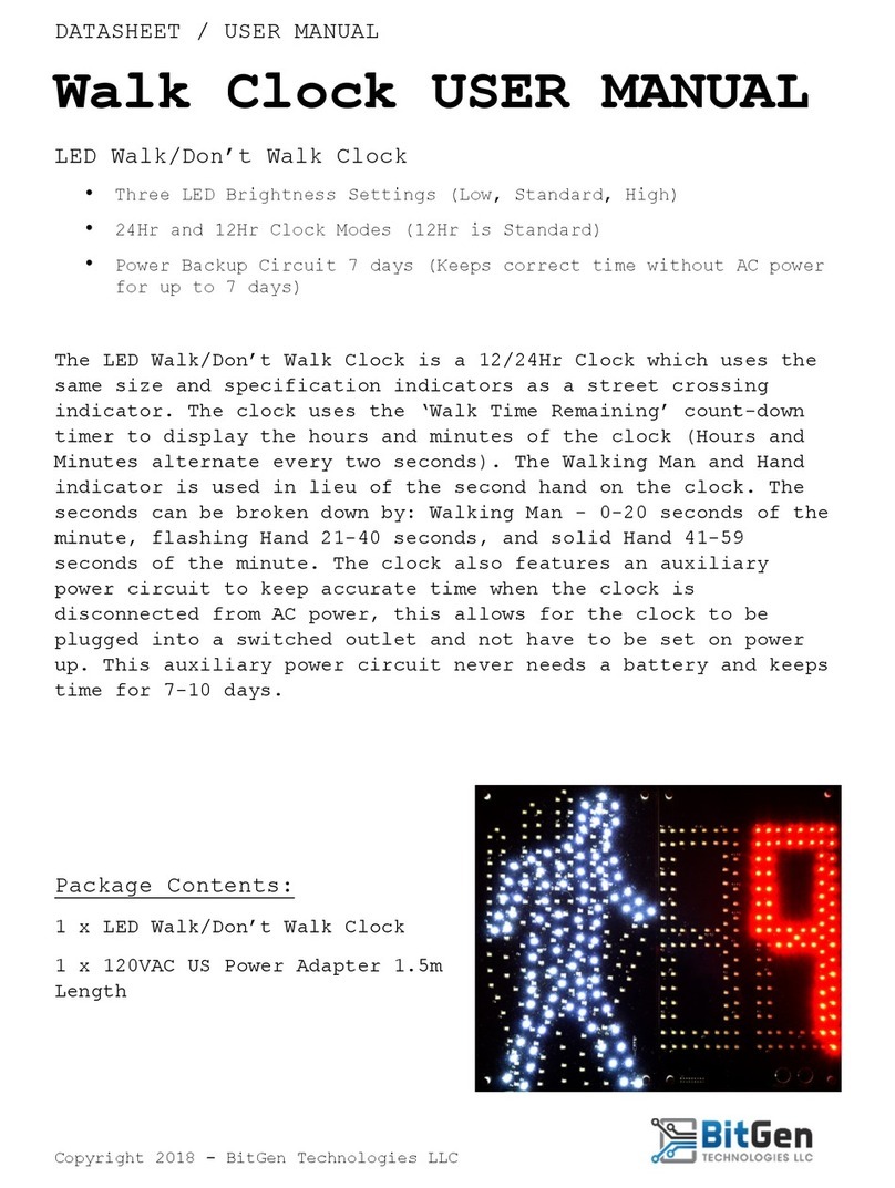
BitGen Technologies LED Walk/Don't Walk Clock user manual
BitGen Technologies

BitGen Technologies LED Walk/Don't Walk Clock user manual

Heathkit GC-1005 Assembly manual

Heathkit

Heathkit GC-1005 Assembly manual

Oregon Scientific PRYSMA RMR221P manual

Oregon Scientific

Oregon Scientific PRYSMA RMR221P manual

Andrew O'Malley DOTKLOK Assembly instructions

Andrew O'Malley

Andrew O'Malley DOTKLOK Assembly instructions

La Crosse Technology WS-8256-AL user manual

La Crosse Technology

La Crosse Technology WS-8256-AL user manual

Mini Gadgets MCPro user manual

Mini Gadgets

Mini Gadgets MCPro user manual

Casio TMR-200 user guide

Casio

Casio TMR-200 user guide

Progetti KALIMERO Directions

Progetti

Progetti KALIMERO Directions

Progetti ILTEMPOSTRINGE Directions

Progetti

Progetti ILTEMPOSTRINGE Directions

La Crosse Technology WT-3141b Quick setup instructions

La Crosse Technology

La Crosse Technology WT-3141b Quick setup instructions

IKEA ROTBLÖTA manual

IKEA

IKEA ROTBLÖTA manual

U-Line Н-2811 instructions

U-Line

U-Line Н-2811 instructions

Silicon Laboratories SI5324 manual

Silicon Laboratories

Silicon Laboratories SI5324 manual

manuals.online logo
manuals.online logoBrands
  • About & Mission
  • Contact us
  • Privacy Policy
  • Terms and Conditions

Copyright 2025 Manuals.Online. All Rights Reserved.

Warm Tube Clock
Assembly Instructions for the „IN-16 Nixie shield“
Document Version: 2011-01-05
www.elektronika.ba
-1-
Warm Tube Clock
Assembly Instructions for the “IN-16 Nixie shield”
Introduction
Congratulations on your purchase of OSH Nixie Tube Clock. In this document you will see all steps
you need to follow in order to successfully assemble the “IN-16 Nixie shield” of this device.
Before we start, please make sure that you have all required parts that come for the “IN-16 Nixie
shield”:
Qty
Value
Device
Parts
2
2x6 MALE PIN HEADER
PINHD-2X6
PIN_MAL_1, PIN_MAL_2
1
3k9
R-EU_0204/2V
R3
1
10k
R-EU_0204/2V
R4
1
10nF
C-EU025-024X044
C3
1
47uF/16V
CPOL-EU-HORI
C1
1
100nF-1uF
C-EUC0805
C2
2
910k
R-EU_0207/10
R1, R2
4
IN-16 NIXIE TUBE
IN-16-X-NEW-NODOT
NIX1, NIX2, NIX3, NIX4
4
LED 1210 COMM ANODE
LED-TRICOLOR
LED1, LED2, LED3, LED4
2
NIXIE-DOT
NIXIE-DOT
NIX-LDOT, NIX-UDOT
1
TLC59401
TLC59401
IC1
4
TLP627 SMD
TLP627V1
OPT1, OPT2, OPT3, OPT4
List of all parts for the “IN-16 Nixie shield”board
All parts should be assembled in correct order, starting from SMD components to low profile
components and finally to high profile ones. Component locations are not marked on PCB because a
“clean look” of the shield is very important. So, component (Part) locations are in the following image
and their values are in the above table.
Note: The assembly of this shield PCB implies that you have already successfully assembled the
“main board” of the Warm Tube Clock.
Warm Tube Clock
Assembly Instructions for the „IN-16 Nixie shield“
Document Version: 2011-01-05
www.elektronika.ba
-2-
Assembly
Heat up your soldering iron, take a deep breath and go for it. The assembly of this PCB is easier than
“main board” PCB since it has very small component count but requires a steady hand. Also, take
your time when soldering the Nixie tubes because you wouldn’t want to solder them crooked.
Step 1
First you need to solder the TLC59401 SMD IC (IC1). This IC should have came already soldered on
your shield PCB so you can skip this step, or read it FYI and see how easy it is to solder complicated
SMD parts at home.
1. Make sure the PCB pad where IC goes is clean from
grease. Rub it with some alcohol just in case.
2. Apply some amount of liquid solder paste. I can’t give
you the exact amount of solder paste to use, as this comes
with experience and pure sense.
Just put the amount you think that will be enough to
solder the entire bottom pad of the TLC59401 IC and not
too much to make a problem.
3. As you can see, it doesn’t look pretty and it doesn’t
have to! You can also put some solder paste on the pin’s
locations so you don’t have to use a soldering iron after
“hot-plating” the IC. You will see what “hot-plating” is
later on.
Warm Tube Clock
Assembly Instructions for the „IN-16 Nixie shield“
Document Version: 2011-01-05
www.elektronika.ba
-3-
4. Now, using your tweezers gently place the component
in its position. Push it all the way to the PCB so it kind of
“glues” itself. Make sure it is centred and placed correctly!
5. It looks something like this before “hot-plating”.
6. Now, find your favourite “hot-plate”. As you can see, I
am using a clothing iron! It works excellent.
7. Turn it around and secure it in place!
Warm Tube Clock
Assembly Instructions for the „IN-16 Nixie shield“
Document Version: 2011-01-05
www.elektronika.ba
-4-
8. Place the PCB onto the “hot-plate” and turn it ON to
pre-heat. Don’t turn the “hop-plate” to maximum
temperature just yet. First put it to half, wait a minute,
and then turn it up to the maximum. The maximum
temperature for a clothing iron is around 210 degrees
Celsius which is just enough to get the job done.
9. Now, what you can (should be able to) see in this
picture is that the soldering paste we previously applied is
slightly starting to melt and liquefy. It might also start to
smoke a bit (depends on the type of your liquid solder) –
so don’t worry that is normal.
The end of the soldering process is when the solder paste
fully melts, just like in the following picture.
10. Now it is time to remove the PCB from the “hot-plate”.
I usually don’t leave it there until it cools down totally, so
after turning the “hot-plate” off I wait about half a minute
and remove the PCB with hands, but very slowly, and
place it on the desk to cool down.
Now it is time to inspect the solder-work. If the pins don’t
look like they have enough solder on them, feel free to fix
the work with your soldering iron. If there are short-
circuits between pins –fix with soldering iron!
The “hot-plate” kind of soldering is required because the
TLC59401 has a bottom GND pad that needs to be
soldered and this is the only way to do it (actually you
could also do this with the hot-air soldering station).
Warm Tube Clock
Assembly Instructions for the „IN-16 Nixie shield“
Document Version: 2011-01-05
www.elektronika.ba
-5-
Step 2
Now we need to solder the RGB LEDs LED1, LED2, LED3 and LED4. We could have done it at the same
time, together with TLC59401, but since it already came soldered on the PCB we have to do it with
the soldering iron.
1. The LEDs are not that small, so soldering should take a
minute or two.
2. Place the LED in the position but keep in mind about its
common Anode pin. The common Anode is marked on the
PCB as you can see –the upper right corner has a white
mark. The first pin on this RGB LED is actually a Cathode of
the RED LED-part, so by following the IC marking
convention the common Anode is the fourth pin of this
RGB LED.
3. After placing the LED in its position, you can hold it in
place using tweezers while firstly soldering it’s any pin
(“tacking” it actually). After “tacking” it into place with
some solder, you can solder the remaining pins and then
go back to solder the “tacked” pin. While soldering these
LEDs, you actually don’t need to touch the LED with the
soldering iron. It is enough to touch the PCB under the
LED’s pin and it will solder it.
Warm Tube Clock
Assembly Instructions for the „IN-16 Nixie shield“
Document Version: 2011-01-05
www.elektronika.ba
-6-
4. Your finished work should look like this.
Warm Tube Clock
Assembly Instructions for the „IN-16 Nixie shield“
Document Version: 2011-01-05
www.elektronika.ba
-7-
Step 3
Now find the “103”C3 capacitor (10nF = 0.01uF). It is used to filter voltage spikes for the TLC59401
IC. It must run flawlessly since every flicker will be visible on the Nixie tubes.
1. Place it and solder it –piece of cake.
Warm Tube Clock
Assembly Instructions for the „IN-16 Nixie shield“
Document Version: 2011-01-05
www.elektronika.ba
-8-
Step 4
Now locate the resistors R3 and R4: 3k9 (3.9k) and 10k, respectively. The 3k9 resistor defines the
current that will be provided to the RGB LEDs (and also to the opto-couplers) –for more information
about this LED current, see the TLC59401 datasheet. The 10k resistor is simply a pull-up resistor for
the BLANK line of the TLC59401 IC. It is there to make sure all LEDs are turned off in case Atmel AVR
doesn’t have the correct firmware loaded.
1. Put them in place and solder them. Left one is the 3k9,
the right one is the 10k.
2. So it looks like this from the bottom view.
Warm Tube Clock
Assembly Instructions for the „IN-16 Nixie shield“
Document Version: 2011-01-05
www.elektronika.ba
-9-
Step 5
Now locate the “2x6” male pin headers: PIN_MAL_1 and PIN_MAL2. These connect the “main board”
and the “shield board”, so make sure they get soldered correctly.
1. Put these into the female pin headers on the “main
board”, all the way in. Now place the shield board on top
of the “main board” like in the picture. This way you will
know that it will fits perfectly!
2. Push it all the way down while soldering, so it doesn’t
“float”! Simply solder both connectors while the PCB is on
top of the “main board” like in the picture.
Warm Tube Clock
Assembly Instructions for the „IN-16 Nixie shield“
Document Version: 2011-01-05
www.elektronika.ba
-10-
Step 6
Now that we have all required parts soldered for TLC59401 to operate, we can test it to see if it
works. This is the first time we can verify our TLC59401 SMD soldering work!
1. Make sure your desk is clean of all wires and solder
remains, and plug in the DC supply to the “main board”
and the LEDs should start blinking in blue after few
seconds!
WARNING!
When you now connect the DC power supply, the
booster circuit will generate around 200V DC. Don’t
touch any part of the device, including the upper shield
PCB!
Now, disconnect the DC power supply, wait a minute for
the high voltage capacitor to empty, and continue
soldering.
But what if it doesn’t work properly?
1. Turn off the DC power supply
2. Make sure you have Atmel AVR placed in its socket on the “main board”
3. Make sure your Atmel AVR has a valid firmware programmed for the Warm Tube Clock with
IN-16 Nixie shield
4. Take your soldering iron and re-solder all pins of TLC59401 IC. Yes, they are tiny but soldering
these pins is really no problem if you use a good soldering flux. That way the solder will stay
only on the pins of TLC59401 making sure they got soldered. Make sure there are no short-
circuits among pins!
5. If after the step 2. didn’t help solve the problem, you really need to use the hot-air station to
re-solder the bottom GND pad of the TLC59401 since clearly your “hot-plate” method didn’t
go as planned.
6. If the LEDs do blink, but not in blue colour –it seems that your LEDs are not the same as ones
I used, so you will need to edit the Warm Tube Clock wt.h file a bit, and recompile the
firmware.