manuals.online logo
Brands
  1. Home
  2. •
  3. Brands
  4. •
  5. NKK SWITCHES
  6. •
  7. Switch
  8. •
  9. NKK SWITCHES FF01 Series User manual

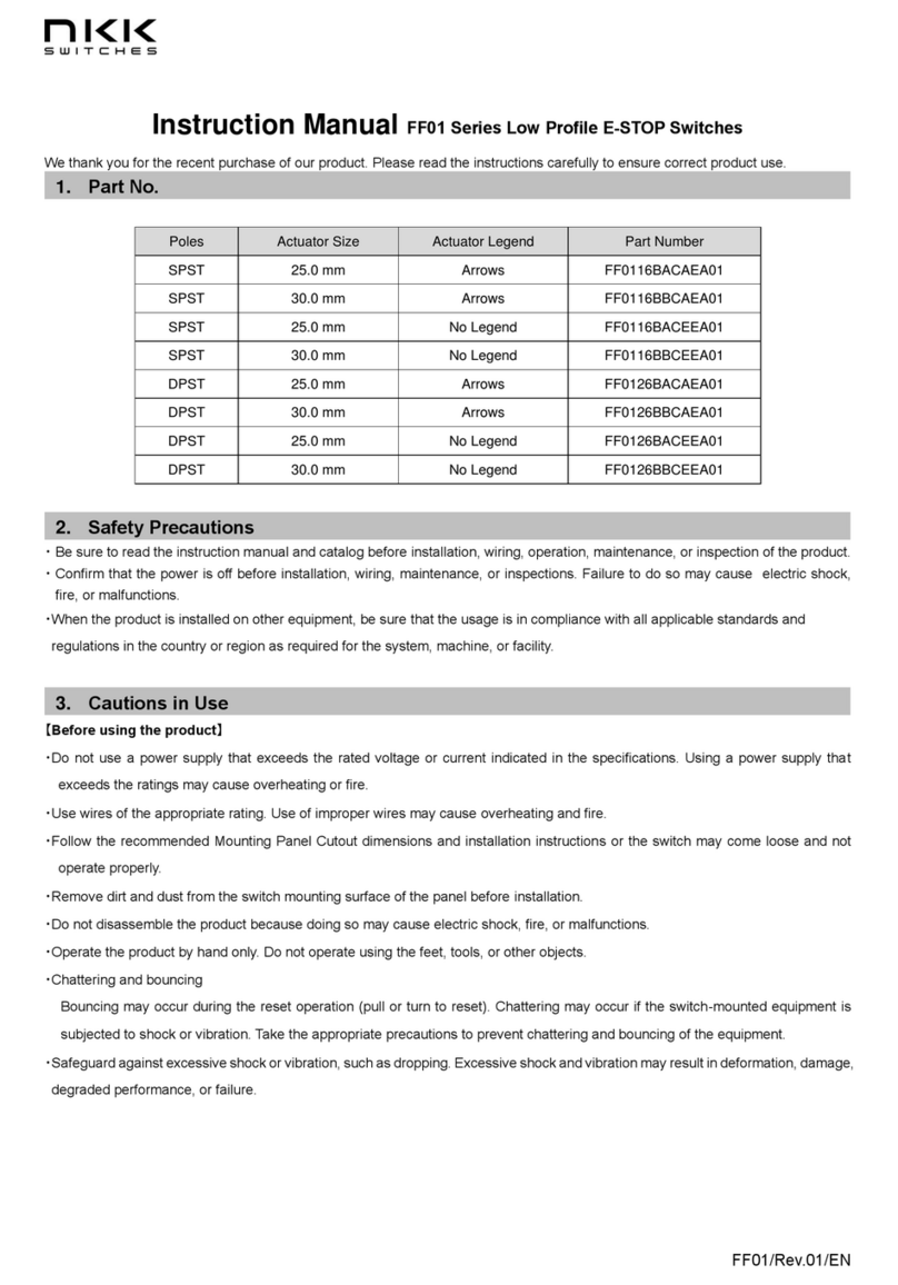
NKK SWITCHES FF01 Series User manual

Series FF01
Emergency Stop Switches
www.nkkswitches.com 1
SAFETY PRECAUTIONS & INSTALLATION INSTRUCTIONS
Installation of Switch & AT220 Protective Guard
* The protective guard complies with international standards. Read carefully to ensure the product will be used properly.
Safety Precautions
• The protective guard is made exclusively for use with NKK’s FF01 Series and should not be used with other types of products.
• Read the FF01 Series Instruction Manual before switch installation, cable connection, operation, maintenance or inspection.
• Confirm power is off before installation, cable connection, maintenance, etc.
• When installing product on other equipment, be sure usage is in compliance with standards and regulations of your country
or region, as required for your system, equipment or facility.
Installation of Switch & Guard into Panel
1. Remove the nut from the switch body.
2. Insert the switch body into the protective guard from the front of
the guard, aligning notch on the o-ring with the anti-rotation tab
on the switch body. Align the anti-rotation tab on the switch body
with the keyway on the guard.
3. Align the anti-rotation tab on the back of guard with the anti-
rotation keyway on the panel.
4. Using the AT119 Socket Wrench, tighten the nut from the back
of the panel (recommended torque 785mN•m).
Installation Height
•To install the switch with the protective guard onto semiconductor
manufacturing equipment, the mounting height range should be 33.0
inches to 64.5 inches (838mm to 1,638mm). The maximum horizontal
reach should be between 7.0 inches and 10.0 inches (178mm to 254mm) (SEMI S8).
• The switch must be installed within 118.0 inches (3.0 meters) from the working position (SEMI S2).
• To install the switch with the protective guard on equipment such as machine tools or processing equipment, the recommended
height range is between 23.5 and 67.0 inches (600mm and 1,700mm) from the floor or platform level (ISO 13850).
Note: To confirm that the switch and protective guard mounted on a device are ISO compliant, see requirements of ISO 13850.
* To comply with the SEMI Standard, it is necessary that “EMO” (Emergency Off) is printed on the switch or on the inside of the
protective guard. Contact NKK Switches for more information.
Height Horizontal Reach (Maximum)
Inches Millimeters Inches Millimeters
64.5 1,638 10.0 254
60.0 1,524 14.5 368
56.0 1,422 17.0 432
52.0 1,321 18.5 470
48.0 1,219 19.0 483
44.0 1,118 18.5 470
40.0 1,016 15.5 394
36.0 914 11.5 292
33.0 838 7.0 178 The table and illustration show the mounting
range for the assembled emergency stop switch
and protective guard. The height and horizontal
reach are determined according to SEMI S8.
Height
Horizontal Reach
Front End of
Equipment
Anti-rotation Keyway
on Panel
Anti-rotation Tab on
Protective Guard
Anti-rotation Keyway
on Protective Guard
Notch on O-ring
Anti-rotation Tab
on Switch Body
Series FF01 Emergency Stop Switches
www.nkkswitches.com
2
Installation of Switch
Safety Precautions
• Read the FF01 Series Instruction Manual before switch installation, cable connection, operation, maintenance or inspection.
• Confirm power is off before installation, cable connection, maintenance, etc.
• When installing product on other equipment, be sure usage is in compliance with standards and regulations of your country
or region, as required for your system, equipment or facility.
• Use the switch at the voltage and current recommendations in the specifications. Exceeding these may cause overheating.
• Use wiring with the appropriate rating.
• Follow recommended panel cutout dimensions and mounting instructions or switch may not operate properly.
• Remove dirt and dust from switch mounting surface of the panel before beginning installation.
• Do not disassemble the product, as it may cause malfunction, electric shock or fire.
• Operate switch by hand only; do not operate using foot, tool or other object.
• Bouncing may occur during a reset operation (pull or turn to reset). If switch-mounted equipment is subjected to shock or
vibration, it may cause chattering. Take appropriate measures to prevent bouncing and chattering on the equipment side.
• Do not drop the switch or apply excessive shock or vibration. Deformation or damage may cause malfunction or performance
degradation.
• After inserting the lead wire into the terminal hole, use a soldering iron to ensure a secure connection.
• If soldering is executed with terminals facing up, avoid allowing the flux to enter the interior of the switch.
• Soldering temperature is 390°C maximum within four seconds.
Usage Environment
• This product is designed for indoor use.
• Avoid using the switch in environments where there is frequent splashing water.
• If the switch becomes wet, wipe off with a dry cloth. Using a switch exposed to water may result in water entering inside. If
the water freezes inside the switch, it may not function properly.
• In an environment where dust and dirt may accumulate, remove deposits
around switch before use. When necessary, a cloth dampened with a
small amount of neutral detergent may be used. Follow using a dry cloth.
Installation of Switch into Panel
1. Remove the nut from the switch body.
2. Insert the switch body into the panel, aligning notch on the o-ring with
the anti-rotation tab on the switch body. Align the anti-rotation tab on
the switch body with the anti-rotation keyway on the panel.
3. Using the AT119 Socket Wrench, tighten the nut from back of panel
(recommended torque 785mN•m).
SAFETY PRECAUTIONS & INSTALLATION INSTRUCTIONS
Anti-rotation Tab
on Switch Body
Notches
on O-ring
Anti-rotation
Keyway
on Panel
7850 East Gelding Drive • Scottsdale, AZ 85260 • Telephone 480.991.0942 • Fax 480.998.1435
www.nkkswitches.com • 1.877.2BUYNKK (228.9655)
Eective Date May 2020
This manual suits for next models

8

Other NKK SWITCHES Switch manuals

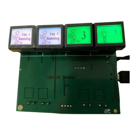
NKK SWITCHES SmartDisplay Keypad User manual

NKK SWITCHES

NKK SWITCHES SmartDisplay Keypad User manual

NKK SWITCHES FF01 Series User manual

NKK SWITCHES

NKK SWITCHES FF01 Series User manual

NKK SWITCHES FF01 Series User manual

NKK SWITCHES

NKK SWITCHES FF01 Series User manual

NKK SWITCHES IS-S04G1LC-S User manual

NKK SWITCHES

NKK SWITCHES IS-S04G1LC-S User manual

NKK SWITCHES IS-Dev Kit-8 User manual

NKK SWITCHES

NKK SWITCHES IS-Dev Kit-8 User manual

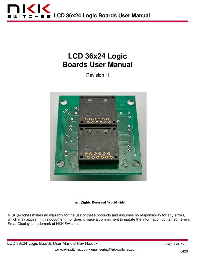
NKK SWITCHES LCD 36x24 Logic User manual

NKK SWITCHES

NKK SWITCHES LCD 36x24 Logic User manual

Popular Switch manuals by other brands

AVCOMM 608FX2 Quick installation guide

AVCOMM

AVCOMM 608FX2 Quick installation guide

Jlso Tec Trade VH M 1 1 1 Series operating manual

Jlso Tec Trade

Jlso Tec Trade VH M 1 1 1 Series operating manual

Southern States RDA Installation instructions manual

Southern States

Southern States RDA Installation instructions manual

Crestron CLW-SLVS1 user guide

Crestron

Crestron CLW-SLVS1 user guide

Trainworx SBB CFF FFS IC 2000 quick guide

Trainworx

Trainworx SBB CFF FFS IC 2000 quick guide

H3C S5120-SI Series Configuration guide

H3C

H3C S5120-SI Series Configuration guide

TP-Link LS105LP installation guide

TP-Link

TP-Link LS105LP installation guide

Belkin BusStation F5U1000 user manual

Belkin

Belkin BusStation F5U1000 user manual

Resource Data Management Mercury PR0018 user guide

Resource Data Management

Resource Data Management Mercury PR0018 user guide

Beninca MLS operating instructions

Beninca

Beninca MLS operating instructions

DeLOCK 62440 datasheet

DeLOCK

DeLOCK 62440 datasheet

HP A12500 Product End-of-Life Disassembly Instructions

HP

HP A12500 Product End-of-Life Disassembly Instructions

Cartek XR USER GUIDE AND INSTRUCTIONS

Cartek

Cartek XR USER GUIDE AND INSTRUCTIONS

Nortel 2000 Using

Nortel

Nortel 2000 Using

NETGEAR FS108 - ProSafe 10/100 Desktop Switch Specifications

NETGEAR

NETGEAR FS108 - ProSafe 10/100 Desktop Switch Specifications

Allied Telesis AT-GS950/16 datasheet

Allied Telesis

Allied Telesis AT-GS950/16 datasheet

IBM 3454-A3C Customer Install Guide

IBM

IBM 3454-A3C Customer Install Guide

Icy Box IB-RP103 Quick installation guide

Icy Box

Icy Box IB-RP103 Quick installation guide

manuals.online logo
manuals.online logoBrands
  • About & Mission
  • Contact us
  • Privacy Policy
  • Terms and Conditions

Copyright 2025 Manuals.Online. All Rights Reserved.