manuals.online logo
Brands
  1. Home
  2. •
  3. Brands
  4. •
  5. NKK SWITCHES
  6. •
  7. Switch
  8. •
  9. NKK SWITCHES FF01 Series User manual

NKK SWITCHES FF01 Series User manual

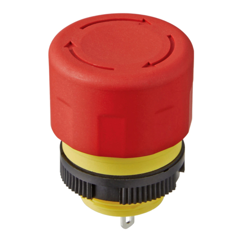
Instruction Manual FF01 Series Low Profile E-STOP Switches
We thank you for the recent purchase of our product. Please read the instructions carefully to ensure correct product use.
1. Part No.
Poles
Actuator Size
Actuator Legend
Part Number
SPST
25.0mm
Arrows
FF0116BACAEA01
SPST
30.0mm
Arrows
FF0116BBCAEA01
SPST
25.0mm
No Legend
FF0116BACEEA01
SPST
30.0mm
No Legend
FF0116BBCEEA01
DPST
25.0mm
Arrows
FF0126BACAEA01
DPST
30.0mm
Arrows
FF0126BBCAEA01
DPST
25.0mm
No Legend
FF0126BACEEA01
DPST
30.0mm
No Legend
FF0126BBCEEA01
2. Safety Precautions
・Be sure to read the instruction manual and catalog before installing, wiring, operation, maintenance, or inspection the product.
・Confirm power is off before installation, wiring, maintenance, or inspections. Failure to do so may cause electric shock, fire,
or malfunctions.
・When the product is installed on other equipment, be sure usage is in compliance with all applicable standards and regulations in
the country or region, as required for the system, machine, or facility.
3. Caution in Use
【Before using the product】
・Do not use a power supply that exceeds the rated voltage or current indicated in the specifications. Using a power supply that
exceeds ratings may cause overheating or fire.
・Use wires of appropriate rating. Use of improper wires may cause overheating and fire.
・Follow recommended “Mounting Panel Cutout” dimensions and installation instruction, or switch may be fixed loose and not operate
properly.
・Remove dirt and dust from the switch mounting surface of the panel before installation.
・Do not disassemble the product as it may cause electric shock, fire, or malfunctions.
・Operate the product by hand only. Do not operate using foot, tool, or other objects.
・Chattering and bouncing
Bouncing may occur during a reset operation (pull or turn to reset). Chattering may occur if the switch-mounted equipment is
subjected to shock or vibration. Take appropriate measures to prevent chattering and bouncing on the equipment side.
・Safeguard against excessive shock or vibration, such as dropping. Excessive shock and vibration may result in deformation, damage,
degraded performance, or failure.
【Soldering】
・After inserting the lead wire into the terminal hole, use a soldering iron to ensure a secure connection.
Incomplete soldering may cause overheating in overheating and fire during use.
・Note that if soldering is performed while the terminal is facing up, the flux may enter the interior of the switch. Perform soldering
carefully.
・The solder resistant temperature is 390°C. Complete the soldering within four seconds.
【Usage Environment】
・The product is designed for indoor use.
・Do not install in locations subject to frequent splashing water.
・If the product becomes wet, wipe off with a dry cloth. Using a switch exposed to water may result in water entering inside; if the
water freezes inside the switch, it may not function properly.
・When using the product in environments subject to accumulations of dust and dirt, remove such accumulations from the area around
the switch before use. Accumulated dust and dirt, may affect switch function.
【Routine Care】
・Use a dry cloth to wipe dirt from the actuator. If the actuator is very dirty, wipe with a cloth dampened with a small amount of neutral
detergent, then wipe dry. (Actuator material: Fiber-reinforced PBT)
4. Installing the Switch
(1) Remove the round nut from the switch main body.
(2) With the notch in the O-ring aligned with the anti-rotation tab on the switch main body, insert the switch body into panel. In this
step, align the anti-rotation tab on the switch main body with the anti-rotation keyway on the panel.
(3) Using the fixing nut wrench (AT119), tighten the round nut from the back side of the panel to the recommended tightening torque
of 785 mN·m.
5. General Specifications
Test specification
UL508/EN60947-5-1/EN60947-5-5
Rated Operating Voltage (Ue)
Rated Operating Current
Resistive Load (DC-12) 24V DC 0.5A
※UL,TÜV certified rating
Rated Insulation Voltage (Ui)
36V DC
Rated Impulse Withstand Voltage
2.5kV
Sealing
Front panel : IP65 (IEC 60529)
Pollution Degree
3
Short-circuit Protection Device
gG10A
Conditional Short-circuit Current
1000A
Ambient Operating Temperature
-25 to +60°C (no freezing)
Ambient Storage Temperature
-45 to +80°C (no freezing)
Operating Force
Push to lock: 10.8N Pull to reset: 8.5N Turn to reset: 0.13 N・m
Minimum Force to achieve direct opening
action of all break contacts
15N
Minimum travel including travel beyond
the minimum travel position
3.0mm
Maximum travel of actuator
4.5mm
Contact Resistance
50 mΩ maximum (initial value)
Insulation Resistance
100 MΩ minimum (500V DC megger)
Overvoltage Category
II
Operation Frequency
600 operations/hour
Shock Resistance
Durability:1,000 m/s2
Malfunction:150 m/s2
Vibration Resistance
Durability:10 to 500 Hz half amplitude:0.35mm,acceleration:50m/s2
Malfunction: 10 to 500 Hz half amplitude:0.35mm,acceleration:50m/s2
Electrical Life/ Mechanical Life
Electrical Life/ Mechanical Life :100,000 operations
Minimum (resistive load),6050 times
Minimum (inductive load (DC-13))
Recommended fixing nut mounting torque
785mN・m
Soldering
Soldering:390°C or lower within 4 seconds
Effective Panel Thicness
Effective Panel Thicness 0.8 to 4.5mm
(Effective Panel Thicness Range with a nameplate or switch guard 0.5 to 3.0mm)
* UL, TÜV certified rating
・UL/ TÜV certified rating: 24 V DC, 0.5 A (DC-13)
Minimum applicable load (reference value) : 5V DC 1mA
(Usage conditions and load types may affect the allowable operating range.)
FF01/Rev.01
6. Mounting panel Cutout
Effective Panel Thicness 0.8 to 4.5 mm
(The thickness is 0.5 to 3.0 mm when the accessory (optional) nameplate and switch guard are installed)
Processing should be in accordance with the installation hole drawing to allow the rotation stop function of the main switch unit to
function properly.
7. Inquiries

This manual suits for next models

8

Other NKK SWITCHES Switch manuals

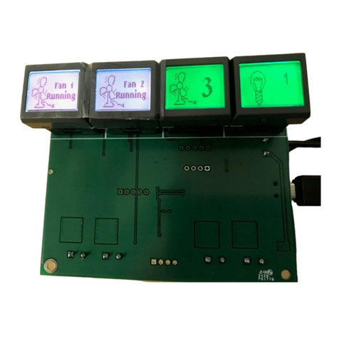
NKK SWITCHES LCD 36x24 Logic User manual
NKK SWITCHES

NKK SWITCHES LCD 36x24 Logic User manual

NKK SWITCHES FF01 Series User manual

NKK SWITCHES

NKK SWITCHES FF01 Series User manual
NKK SWITCHES IS-S04G1LC-S User manual

NKK SWITCHES

NKK SWITCHES IS-S04G1LC-S User manual

NKK SWITCHES SmartDisplay Keypad User manual
NKK SWITCHES

NKK SWITCHES SmartDisplay Keypad User manual

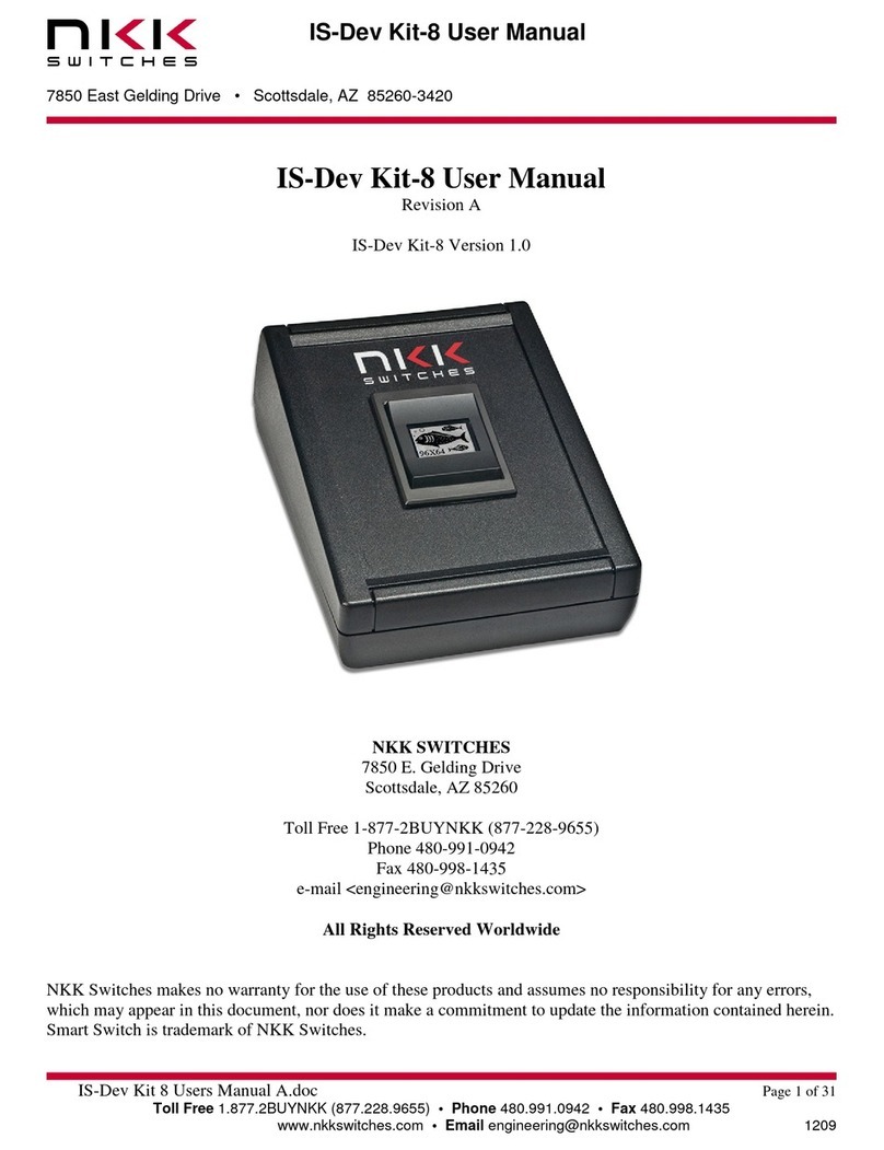
NKK SWITCHES IS-Dev Kit-8 User manual

NKK SWITCHES

NKK SWITCHES IS-Dev Kit-8 User manual
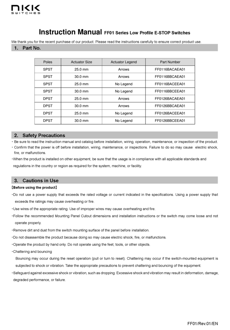
NKK SWITCHES FF01 Series User manual

NKK SWITCHES

NKK SWITCHES FF01 Series User manual

Popular Switch manuals by other brands

Pilz PSEN ma1.3n-20 operating instructions

Pilz

Pilz PSEN ma1.3n-20 operating instructions

Sony MVS-8000 user guide

Sony

Sony MVS-8000 user guide

Vemer DUET-D user manual

Vemer

Vemer DUET-D user manual

Johnson Controls IQ4 user guide

Johnson Controls

Johnson Controls IQ4 user guide

Altusen ALTUSEN KH2508 user manual

Altusen

Altusen ALTUSEN KH2508 user manual

Alcatel-Lucent OmniAccess 4504 installation guide

Alcatel-Lucent

Alcatel-Lucent OmniAccess 4504 installation guide

KROHNE OPTISWITCH 3300 C Handbook

KROHNE

KROHNE OPTISWITCH 3300 C Handbook

Cudy GS1024 Quick installation guide

Cudy

Cudy GS1024 Quick installation guide

Qvis POESWITCH-4 installation guide

Qvis

Qvis POESWITCH-4 installation guide

Leonton BG5-1204-SFP-24 Series user manual

Leonton

Leonton BG5-1204-SFP-24 Series user manual

Audio Authority Ascentic MH10-HD user manual

Audio Authority

Audio Authority Ascentic MH10-HD user manual

Cisco Catalyst 8510 quick reference

Cisco

Cisco Catalyst 8510 quick reference

Digisol DG-GS1528HP user manual

Digisol

Digisol DG-GS1528HP user manual

FIBARO FGS-2 3 Series operating manual
FIBARO

FIBARO FGS-2 3 Series operating manual

ADTRAN 600 Series Interface guide

ADTRAN

ADTRAN 600 Series Interface guide
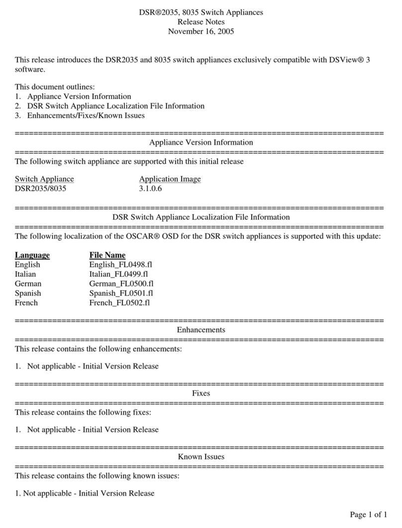
Avocent DSR Series DSR2035 release note

Avocent

Avocent DSR Series DSR2035 release note

Cooper Crouse-Hinds CEAG KO operating instructions
Cooper

Cooper Crouse-Hinds CEAG KO operating instructions

Brooks Instrument IPS122 Series Installation and operation manual

Brooks Instrument

Brooks Instrument IPS122 Series Installation and operation manual

manuals.online logo
manuals.online logoBrands
  • About & Mission
  • Contact us
  • Privacy Policy
  • Terms and Conditions

Copyright 2025 Manuals.Online. All Rights Reserved.