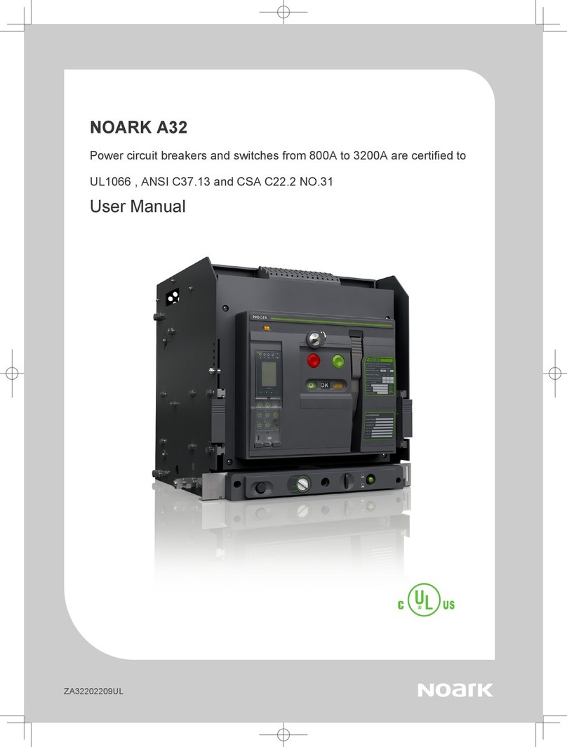
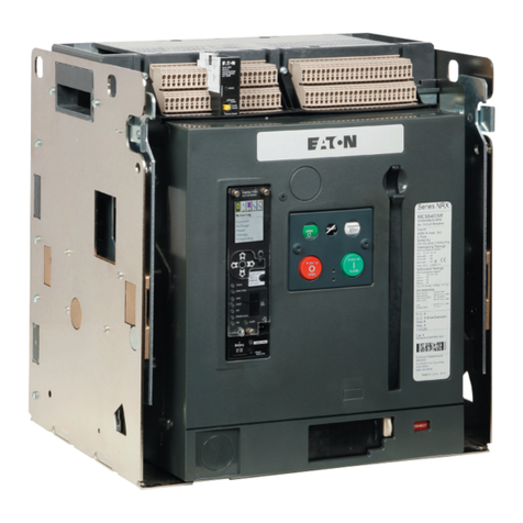
Noark A32 User manual

Air Circuit Breaker
Usage Manual
ZA32202110UL
NOARK A32
Power circuit breakers and switches from 800A to 3200A are certified to
UL1066 , ANSI C37.13 and CSA C22.2 NO.31
User Manual

Installation manual
Overview 01
Selection Guide 02
Product parameters 06
Environmental Conditions 07
Storage 08
Necessary tools 09
Unpacking 10
Handling 12
Installation Dimension 15
Accessories 24
Secondary circuit wiring 29
Smart Unit Operating Instruction
Profile of SU 34
Main menus 41
Menu 42
Overview of functions 45
Appendix 46

User Manual 01
This equipment should be installed, operated, serviced and maintained only by professional personnel.
Noark Electric is not responsible for any consequences caused by non-compliance with this the manual.
After unpacking the product, check for any damage and the integrity of other items.
Do not install the product in inflammable, explosive, humid and condensing environment.
Do not install the product at places where gas medium can cause metal corrosion and insulation damage.
Connect the product to the proper power supply and standard wires.
Leave sufficient space and safe distance around the product.
Do not touch the conductive parts during operation.
Disconnect all the power sources during installation and maintenance.
Failure to follow the above instructions may result in equipment damage, personal injury or even death.
Environmental protection
To protect environment, this product and its components should be disposed properly as industrial waste upon
end of life; or delivered to recycling plant who will dismantle and recycle the product according to relevant
national regulations.
Cet équipement doit être installé, opéré, réparé et entretenu par du personnel professionnel.
Noark Electric n'est pas responsable des conséquences causées par le non-respect de ce manuel.
Après avoir déballé le produit, vérifier l'absence de dommages et l'intégrité des autres éléments.
Ne pas installer le produit dans un environnement inflammable, explosif, humide et condensé.
Ne pas installer le produit dans un endroit avec un milieu gazeux qui pourrait endommager la corrosion du
métal et l'isolation.
Connecter le produit à l'alimentation électrique appropriée et aux câbles standard.
Laisser suffisamment d'espace et une distance de sécurité autour du produit.
Ne pas toucher les parties conductrices pendant le fonctionnement.
Débrancher toutes les sources d'alimentation avant l'installation et la réparation.
Le non-respect des instructions ci-dessus peut entraîner des dommages matériels, des blessures
corporelles ou même la mort.
Protection environnementale
Pour protéger l'environnement, ce produit et ses composants doivent être correctement éliminés en tant que
déchets industriels en fin de vie; ou livré à une usine de recyclage qui démontera et recyclera le produit
conformément aux réglementations nationales applicables.
UL 1066、ANSI C37.13、ANSI C37.16、ANSI C37.17、ANSI C37.50,CSA C22.2 NO.31
UL file number: E502732
Codes and Standards
1
2
4
3
6
5
7910111213 8
141516
Overview
1. Brand
2. Opening push-button (O)
3. Closing push-button (I)
4. Manual spring charge handle
5. Nameplate
6. Closing ready indicator
9. Spring charged/discharged indicator
10. Rotary handle operation hole
C
h
a
r
g
e
d
Discharged
a) Spring charged
b) Spring discharged
a) ready
b) not ready
a) opening
b) closing
OFF
ON
OK
OK
7. Cassette position lock(manually
reset after injection)
8. Padlock
11. Main contact position indicator
12. Indicator for Disconnect, Test,Connect
position
13. Rotary handle
14. Smart Unit
15. Trip reset button
16. Control circuit wiring terminal

User Manual 03User Manual 02
Selection Guide
A32 H3F H 800
I II III IV V VI VII
I
Noark UL1066 power circuit breakers
A: Circuit breakers
ASD: Non-automatic switches
II Frame Size
32: 3200A
III Interrupting/short time withstand current
Q: 65kA, R: 85kA, H: 100kA
IV
Number of poles:
3– 3 Pole
4 – 4 Pole
V
Installation
F: Fixed ; D: withdrawable
* 3200A only provided with withdrable type.
VI
H: Horizontal ; V: Vertical
* 3200A only provided with vertical type.
* contact Noark sales for other configuration.
VII
Rated current:
800– 800A
1600 – 1600A
2000 – 2000A
2500 – 2500A
3200 – 3200A
Catalog designation for cassette
Catalog Designation for Auxiliary contact
Catalog Designation for Under voltage Trip
Catalog Designation for Motor Operator Device
Catalog Designation for Shunt Trip
Catalog Designation for Closing Release/Shunt Close
AX 12 N 44
I II III IV
IAX: Auxiliary contact
II 12: For 3200A PCB
III N: UL
IV
Contact configuration
44: 4NO+4NC, 66: 6NO+6NC
44C: 4NO/NC, 66C: 6NO/NC
SHT 12 N A
I II III IV
ISHT: Shunt trip release
SHTD: second shunt trip release
II 12: For 3200A PCB
III N: UL
IV Control voltage
A: 24-30VDC, B: 48-60VDC, C: 110-130VAC/DC, D: 208-240VAC/DC
XF 12 N A
I II III IV
I XF: Shunt close
II 12: For 3200A PCB
III N: UL
IV Control voltage
A: 24-30VDC, B: 48-60VDC, C: 110-130VAC/DC, D: 208-240VAC/DC
UVT 12 N A
I II III IV
IUVT: Under voltage trip
II 12: For 3200A PCB
III N: UL
IV Control voltage
A: 24VDC, B: 48VDC, C: 110 - 130VAC/DC, D: 208 - 240VAC/DC E: 380-415VAC
MD 12 N C
I II III IV
I MD: Motor operator Device
II 12: For 3200A PCB
III N: UL
IV Control voltage
A: 24-30VDC, B: 48-60VDC, C: 110-130VAC/DC, D: 208-240VAC/DC
Selection Guide
CAS 12 N 3V3200
III III IV V VI
I CAS: Cassette
II Frame size
12: 3200A
III N: UL
IV
Pole
3: 3P
4: 4P
V
H: Horizontal
V: Vertical
* 3200A only available with vertical wiring.
VI
Rated current
1600: 800A, 1600A,
2500: 2000A, 2500A,
3200: 3200A
Catalog Designation for Trip unit
SU 30 NHA
I II III IV V
I SU: Smart unit
II Protection type
20: LI, 30: LSI, 40: LSIG
III N: UL
IV
Measurement type
M: Basic without measurement (LED display)
A: Ammeter (LCD display)
H: Harmonics (LCD display)
VControl voltage
A: 24VDC,D: 110-130VAC, D: 208-240VAC

User Manual 05User Manual 04
Catalog Designation for Phase barrier for withdrawable type
Catalog Designation for Rear connection plate
Catalog Designation for Door interlocks for withdrawable type
Catalog Designation for Mechanical Interlocks with cables
VPEC 12 N S
I II III IV
IVPEC: Door interlocks for withdrawable type
II 12: For 3200A PCB
III N: UL
IV P: Position interlock
S: Status interlock
IPA 12 N
I II III
I IPA: Mechanical Interlocks with cables
II 12: For 3200A PCB
III N: UL
DPS 12 N 2
I II III IV
IDPS: Phase barrier for withdrawable type
II 12: For 3200A PCB
III N: UL
IV 2: 2 pcs for 3P
3: 3 pcs for 4P
RCP 12 N 3F3200
I II III IV V VI
I RCP: Rear connection plate
II 12: For 3200A PCB
III N: UL
IV 3: 3P, 4: 4P
V
F: Fixed
D: Withdrawable
* 3200A only provided with vertical connection in withdrawable type.
VI
1600: 800A,1600A
2500: 2000A,2500A
3200: 3200A
Selection Guide Selection Guide
Catalog Designation for Position indicator
EF 12 N
I II III
I EF: Position indicator
II 12: For 3200A PCB
III N: UL
Catalog Designation for OFF position keylock
KLK 12 N 1
I II III IV
I KLK: OFF position keylock
II 12: For 3200A PCB
III N: UL
IV 1: 1 lock 1 key, 2: 2 locks 1 key, 3: 3 locks 2 keys
Catalog Designation for Doorframes for fixed type
Catalog Designation for Doorframes for Doorframes for withdrawable type
CDP 12 N
I II III
ICDP: Doorframes for fixed type
II 12: For 3200A PCB
III N: UL
DDP 12 N
I II III
IDDP: Doorframes for withdrawable type
II 12: For 3200A PCB
III N: UL
Catalog Designation for Phase barrier for fixed type
PHS 12 N 2
I II III IV
IPHS: Phase barrier for fixed type
II 12: For 3200A PCB
III N: UL
IV 2: 2 pcs for 3P
3: 3 pcs for 4P
Catalog Designation for Pushbutton lock device
VBP 12 N
I II III
IVBP: Pushbutton lock device
II 12: For 3200A PCB
III N: UL

User Manual 07User Manual 06
1PCS
A32
Conform standard:
UL 1066/ANSI C37.13
CSA C22.2 No.31
12345678912345679812345678912345679 8
A32H3D3200
UVT12NA
XF12NA
SHT12NA
NOARK Electrics (shanghai) Co.,Ltd
Power Circuit Breaker
AX66
MD12NA
SU30NHA
File E502732
A32
Conform standard:
UL 1066/ANSI C37.13
CSA C22.2 NO.31
123456789123456798123456789123456798
A32H3D3200
UVT 12NA
XF 12NA
SHT 12NA
NOARK Electrics (shanghai) Co.,Ltd
Power Circuit Breaker
AX 66
MD 12NA
SU 30NHA
FileE502732
1
1
Product parameters
Type A32Q A32R A32H ASD32Q ASD32R ASD32H
Pole 3P/4P 3P/4P
Installation Fixed/Withdrawable Fixed/Withdrawable
Rated current(A) Fixed:800/1600/2000/2500
Withdrawable:800/1600/2000/2500/3200
Fixed:800/1600/2000/2500
Withdrawable:800/1600/2000/2500/3200
Rated Maximum Valatge(V) 254/508/635 254/508/635
Frequency(Hz) 50/60 50/60
Interrupting rating at rated maximum voltage (kA)
254V 65 85 100 65 85 100
508V 65 85 100 65 85 100
635V 65 85 100 65 85 100
Short time withstand current (kA)
254V 65 85 100 65 85 100
508V 65 85 100 65 85 100
635V 65 85 100 65 85 100
operating time(ms) open <70 <70
close <40 <40
life cycle(time)
mechanical without maintenance 10000 10000 10000 10000 10000 10000
with maintenance / / / / / /
electrical without maintenance 6000 6000 6000 6000 6000 6000
with maintenance / / / / / /
Enclosure dimension
H×W×D(in/mm)
withdrawable
3P
21.65×23.62×18.11
(550×520×460)
Ventilation Area 9092mm²
21.65×23.62×18.11
(550×520×460)
Ventilation Area 9092mm²
4P
21.65×25×18.11
(550×635×460)
Ventilation Area 11963mm²
21.65×25×18.11
(550×635×460)
Ventilation Area 11963mm²
fixed
3P 21.65×20.47×14.17
(550×520×360)
21.65×20.47×14.17
(550×520×360)
4P 21.65×25×14.17
(550×635×360)
21.65×25×14.17
(550×635×360)
Environmental Conditions
Ambient temperature
Altitude
Humidity
Rated
Current(A)
Temperature(℃)
<40 45 50 55 60 65 70
800 100% 100% 100% 100% 100% 100% 100%
1000 100% 100% 100% 100% 100% 100% 100%
2000 100% 100% 100% 100% 100% 100% 93%
2500 100% 95% 92% 88% 83% 80% 75%
3200 100% 95% 92% 88% 83% 80% 75%
Altitude(m)
<2000 2600 3900 4900
Rated Voltage(V) 1xUe 0.95xUe 0.8xUe 0.7xUe
Rated Current(A) 1xIn 0.99xIn 0.96xIn 0.94xIn
A32 Circuit breakers can operate in the following environmental conditions:
With M Smart Unit: -40℃~ 70℃;
With H Smart Unit: -20℃~ 70℃;
A32 Circuit breakers can operate at higher temperatures than the reference temperature 40℃,in this case,the derating coefficients
shown in the table must be applied.
A32 Circuit breakers do not undergo changes in rated performance up to 2000m.Beyond this altitude ,the derating coefficients shown in
the table must be applied.
The relative humidity does not exceed 50% at 40℃,the monthly average maximum of relative humidity in the wettest month does not
exceed 90%.
The effect of surface condensation caused by temperature changes on product performance should be taken into consideration.

User Manual 09User Manual 08
1PCS
A32
Conform standard:
UL 1066/ANSI C37.13
CSA C22.2 No.31
12345678912345679812345678912345679 8
A32H3D3200
UVT12NA
XF12NA
SHT12NA
NOARK Electrics (shanghai) Co.,Ltd
Power Circuit Breaker
AX66
MD12NA
SU30NHA
File E502732
A32
Conform standard:
UL 1066/ANSI C37.13
CSA C22.2 NO.31
123456789123456798123456789123456798
A32H3D3200
UVT 12NA
XF 12NA
SHT 12NA
NOARK Electrics (shanghai) Co.,Ltd
Power Circuit Breaker
AX 66
MD 12NA
SU 30NHA
FileE502732
1
1
installation bolt:Hex Cap Screws:
Hex Cap Screws :
7/16 in x 2 3
4in
17
0.67
7/16 in x 2 3
4in

User Manual 11User Manual 10
Handling
800A/1600A
187/85 198/90
282/128 297/135 330/150
242/110 253/115
364/165 375/170 419/190
2000A/2500A 3200A
unit : lb/kg
Withdrawable
7. Pull out the main breaker to maximum extent
Nameplate example
LOW VOLTAGE AC POWER CIRCUIT BREAKER
UL 1066/ANSI C37.13/CSA C22.2 No.31
Frame Size:3200A Frequency:50/60Hz
Rated Continuous Current: Poles:
Cat.
MFG.Date:
Serial No. : E510966
MADE IN CHINA
Rated Maximum Voltage(V)
Rated Short Circuit Current(kA)
Short-Time Withstand Current
(kA,0.5s)
254 508 635
Instruction Manual:
5. Press and hold pull out button
6. Pull out the main breaker
Rotate handle indicator
to disconnect position
Connected
Test
Disconnected

User Manual 13User Manual 12
Handling
800A/1600A
187/85 198/90
282/128 297/135 330/150
242/110 253/115
364/165 375/170 419/190
2000A/2500A 3200A
unit : lb/kg
Handling
NOTE: Weight of the circuit breakers with packaging and standard configurations.

User Manual 15User Manual 14
Handling
Cassette�only
Model�1
Main�breaker�only
Model�1
800A/1600A
Vertical installation
Fixed type
14.61(371)
12.91(328)
12.24(311)
10.55(268)
8×φ0.24(6)
in/mm

User Manual 17User Manual 16
2000A/2500A
Vertical installation
800A/1600A
Horizontal installation
Fixed typeFixed type
14.61(371)
12.91(328)
12.24(311)
10.55(268)
8×φ0.24(6)
14.61(371)
12.91(328)
12.24(311)
10.55(268)
8×φ0.24(6)
in/mm in/mm

User Manual 19User Manual 18
2000A/2500A
Horizontal installation
Withdrawable typeFixed type
14.61(371)
12.91(328)
12.24(311)
10.55(268)
8×φ0.24(6)
800A/1600A
Vertical installation
14.61(371)
12.91(328)
6.10(155)5.79(147)
14.88(378)
1.85(47)
10.55(268)
0.85(21.5)
(Disconnection position)
(Connection position)
8×φ0.24(6)
in/mm in/mm

User Manual 21User Manual 20
Withdrawable type
2000A/2500A
Vertical installation
800A/1600A
Horizontal installation
Withdrawable type
14.61(371)
12.91(328)
6.10(155)5.79(147)
14.88(378)
1.85(47)
10.55(268)
0.85(21.5)
8×φ0.24(6)
14.61(371)
12.91(328)
6.10(155)5.79(147)
14.88(378)
1.85(47)
10.55(268)
0.85(21.5)
8×φ0.24(6)
(Connection Position)
(Disconnection Position)
in/mm in/mm

User Manual 23User Manual 22
Withdrawable type
3200A
Vertical installation
2000A/2500A
Horizontal installation
Withdrawable type
14.61(371)
12.91(328)
6.10(155)5.79(147)
14.88(378)
1.85(47)
10.55(268)
0.85(21.5)
8×φ0.24(6)
14.61(371)
12.91(328)
6.10(155)5.79(147)
14.88(378)
1.85(47)
10.55(268)
0.85(21.5)
(Disconnection position)
(Connection position)
8×φ0.24(6)
in/mm in/mm

User Manual 25User Manual 24
Accessories Accessories
Undervoltage release/UVT Auxiliary contact/AX
Shunt trip release/SHT Motor operator
Closing release/XF Miss insertion prevent device
The auxiliary contact remotely monitors ON/OFF position of power circuit breaker or Non-automatic
Switch from remote place.
Contact configuration:
44: 4NO and 4NC;66: 6NO and 6NC;
44C: 4NO or 4NC;66C: 6NO or 6NC.
The electric motor charges the closing spring of mechanism when the circuit breaker is closed.
Factory installed only.
Mechanical charging handle can be used when maintaining or without power supply.
Equipped with a limit switch contact which signals that spring is charged.
When main breaker is inserted into the cassette, if the rating of main breaker does not match the
cassette, it will mechanically prevent main breaker to be inserted in the cassette.
The installation method is variable according to ratings.
The undervoltage release is an optional device on both manually and electrically operated circuit
breakers. It opens the breaker when its supply voltage falls to 30–60% of rated voltage. If the release
is not energized to 85% of its supply volt
age, the circuit breaker cannot be closed electrically or manually.
Undervoltage release ratings:
Control
voltages
Operational
voltage
range
85–110%
Dropout
voltage
30–60%
Inrush/
continuous
power
consumption
Opening
time (ms)
24 Vdc 20–26 Vdc 7–14 Vdc 250 W/4.5 W 70
48 Vdc 41–53 Vdc 14– 29 Vdc 275 W/4.5 W 70
110-130 Vac/Vdc 94–143 Vac/Vdc 33–78Vac/ Vdc 275 W/4.5 W 70
200-240Vac/ Vdc 170–264V ac/Vdc 60–144 Vac/ Vdc 275 W/4.5W 70
380–415 Vac 323–457 Vac 114–249 Vac 450 W/4.5W 70
The shunt trip is an optional device on circuit breakers.It opens the circuit breaker
instantaneously when its coil is energized by a voltage input.
Shunt trip ratings:
Control
voltages
Operational
voltage
range
70–110%
Inrush/
continuous
power
consumption
Opening
time (ms)
24-30 Vdc 17– 33 Vdc 250 W/4.5 W 35
48-60 V dc 34–66 V dc 275 W/4.5 W 35
110-130 Vac/Vdc 77–143Vac/Vdc 275 W/4.5 W 35
208-240Vac/ Vdc 146–264V ac/ Vdc 275 W/4.5W 35
The closing release is an optional device. It remotely closes the circuit breaker
when the coil is energized by a voltage input.
Closing release ratings:
Control
voltages
Operational
voltage
range
85–110%
Inrush/
continuous
power
consumption
Opening
time (ms)
24-30 Vdc 20– 33 Vdc 250 W/4.5 W 35
48-60 V dc 41–66 V dc 275 W/4.5 W 35
110-130 Vac/Vdc 94–143Vac/Vdc 275 W/4.5 W 35
208-240Vac/ Vdc 177–264V ac/ Vdc 275 W/4.5W 35
Voltage /V Rated Current /A
AC
240 5
480 2
DC
110 0.25
220 0.25
User Manual 24
Accessories
Undervoltage release/UVT
Shunt trip release/SHT
Closing release/XF
The undervoltage release is an optional device on both manually and electrically operated circuit
breakers. It opens the breaker when its supply voltage falls to 30–60% of rated voltage. If the release
is not energized to 85% of its supply volt
age, the circuit breaker cannot be closed electrically or manually.
Undervoltage release ratings:
Control
voltage
Operational
voltage
range
85–110%
Dropout
voltage
30–60%
Inrush /
continuous
power
consumptio n Opening
time (ms)
24 Vdc 20–26 Vdc 7–14 Vdc 250 W/4.5 W 70
48 Vdc 41–53 Vdc 14– 29 Vdc 275 W/4.5 W 70
110-130 Vac/Vdc 94–143 Vac/Vdc 33–78Vac/ Vdc 275 W/4.5 W 70
200-240Vac/ Vdc 170–264V ac/Vdc 60–144 Vac/ Vdc 275 W/4.5W 70
380–415 Vac 323–457 Vac 114–249 Vac 450 W/4.5W 70
The shunt trip is an optional device on circuit breakers.It opens the circuit breaker
instantaneously when its coil is energized by a voltage input.
Shunt trip ratings:
Control
voltage
Operational
voltage
range
70–110%
Irush/
continuous
power
consumptio n Opening
time (ms)
24-30 Vdc 17– 33 Vdc 250 W/4.5 W 35
48-60 V dc 34–66 V dc 275 W/4.5 W 35
110-130 Vac/Vdc 77–143Vac/Vdc 275 W/4.5 W 35
208-240Vac/ Vdc 146–264V ac/Vdc 275 W/4.5W 35
The closing release is an optional device. It remotely closes the circuit breaker
when the coil is energized by a voltage input.
Closing release ratings:
Control
voltage
Operational
voltage
range
85–110%
Inrush/
continuous
power
consumptio n Opening
time (ms)
24-30 Vdc 20– 33 Vdc 250 W/4.5 W 35
48-60 V dc 41–66 V dc 275 W/4.5 W 35
110-130 Vac/Vdc 94–143Vac/Vdc 275 W/4.5 W 35
208-240Vac/ Vdc 177–264V ac/Vdc 275 W/4.5W 35
User Manual 24
Accessories
Undervoltage release/UVT
Shunt trip release/SHT
Closing release/XF
The undervoltage release is an optional device on both manually and electrically operated circuit
breakers. It opens the breaker when its supply voltage falls to 30–60% of rated voltage. If the release
is not energized to 85% of its supply volt
age, the circuit breaker cannot be closed electrically or manually.
Undervoltage release ratings:
Control
voltage
Operational
voltage
range
85–110%
Dropout
voltage
30–6 0%
Inrush/
continuous
power
consumptio n Opening
time (ms)
24 Vdc 20–26 Vdc 7–14 Vdc 250 W/4.5 W 70
48 Vdc 41–53 Vdc 14– 29 Vdc 275 W/4.5 W 70
110-130 Vac/Vdc 94–143 Vac/Vdc 33–78Vac/ Vdc 275 W/4.5 W 70
200-240Vac/ Vdc 170–264V ac/Vdc 60–144 Vac/Vdc 275 W/4.5W 70
380–415 Vac 323–457 Vac 114–249 Vac 450 W/4.5W 70
The shunt trip is an optional device on circuit breakers.It opens the circuit breaker
instantaneously when its coil is energized by a voltage input.
Shunt trip ratings:
Control
voltage
Operational
voltage
range
70–110%
Irush/
continuous
power
consumptio n Opening
time (ms)
24-30 Vdc 17– 33 Vdc 250 W/4.5 W 35
48-60 V dc 34–66 V dc 275 W/4.5 W 35
110-130 Vac/Vdc 77–143Vac/Vdc 275 W/4.5 W 35
208-240Vac/ Vdc 146–264V ac/Vdc 275 W/4.5W 35
The closing release is an optional device. It remotely closes the circuit breaker
when the coil is energized by a voltage input.
Closing release ratings:
Control
voltage
Operational
voltage
range
85–110%
Inrush/
continuous
power
consumptio n Opening
time (ms)
24-30 Vdc 20– 33 Vdc 250 W/4.5 W 35
48-60 V dc 41–66 V dc 275 W/4.5 W 35
110-130 Vac/Vdc 94–143Vac/Vdc 275 W/4.5 W 35
208-240Vac/ Vdc 177–264V ac/Vdc 275 W/4.5W 35
to
Voltage /V Rated Current /A
AC 240 5
480 2
DC 110 0.25
220 0.25
to
Voltage /V Rated Current /A
AC 240 5
480 2
DC 110 0.25
220 0.25
to
Voltage /V Rated Current /A
AC 240 5
480 2
DC 110 0.25
220 0.25
to
Voltage /V Rated Current /A
AC 240 5
480 2
DC 110 0.25
220 0.25

User Manual 27User Manual 26
Safety shutter OFF position keylock/KLK
Safety shutter lock Pushbutton lock device/VBP
Mechanical interlocks with cables Doorframes
It is the automatic safety device to protect the connectors of main circuits by cutting off dagerous
contact from outside while the breaker is draw out. When the main breaker is drawn in, the safety
shutter is automatically open.
Only available for withdrawable circuit breaker & non-automatic switch.
Suitable for A32 Power circuit breaker and ASD32 No-automatic switch
Block a breaker in OFF position to ensure the breaker can not be closed
One circuit breaker is provided with one lock and one key
Two circuit breakers are provided with two locks and one key
Three circuit breakers are provided with three locks and two keys
When the main breaker is at disconnected position, lock the safety shutter to provent main breaker
pushed in.
Only available for withdrawable circuit breaker & non-automatic switch.
Lock is not provided.
Diameter of the lock should be 0.12in to 0.22in.
The cover prevents the access to control push button of the breaker
Factory instolled only
Scope of delivery: Lockable cover (lock with key is not a part of delivery)
For mutual interlocking of 2 or 3 (in preparation) breakers
Mechanical interlock with cable
Cable length for maximum distance of mounting positions of interlocks 78in(2m)
Suitable for A32 Power circuit breaker and ASD32 No-automatic switch
Scope of delivery: 2 interlocks and 2 cables (2 breakers version), 3 interlocks and 6 cables (3 breakerss version)
In the scope of delivery for each PCB
Degree of protection IP40
Can be ordered separately as a spare part
Accessories Accessories
78in/2m(max)
AB
AB
0
1
0
0
01
Circuit diagram On/Off state
User Manual 26
Safety shutter
Safety shutter lock
Mechanical interlocks with cables
It is the automatic safety device to protect the connectors of main circuits by cutting off dangerous
contact from outside while the breaker is draw out. When the main breaker is drawn in, the safety
shutter is automatically open.
Only available for withdrawable circuit breaker & non-automatic switch.
rp ot rettuhs ytefas eht kcol ,noitisop detcennocsid ta si rekaerb niam eht nehW event main
breaker pushed in.
Only available for withdrawable circuit breaker & non-automatic switch.
Lock is not provided.
Diameter of the lock should be 0.12in to 0.22in.
For mutual interlocking of 2 or 3 (in preparation) breakers
Mechanical interlock with cable
Cable length for maximum distance of mounting positions of interlocks 78in(2m)
Suitable for A32 Power circuit breaker and ASD32 No-automatic switch
Scope of delivery: 2 interlocks and 2 cables (2 breakers version), 3 interlocks and 6 cables (3 breakers version)
Accessories
78in/2m(max)
AB
AB
0
1
0
0
01
Circuit diagram On/Off state

User Manual 29User Manual 28
Position indicator/EF
Phase barriers
Indicate position of the breaker - connected, testing, disconnected
For withdrawable type devices only
3 CO contacts, one contact for each breaker position
Connected to secondary terminals #58, 59, 60 (Connected), #61, 62, 63 (Test), #64, 65, 66
(Disconnected)
Factory installed only - in the scope of delivery there are additional secondary terminals #58-66
Improve insulation level between main terminals
Delivered as set (2pcs for 3P version, 3 pcs for 4P version)
One plate for every line side & load side.
Accessories Accessories
Plate for withdrawable 800A/1600A/2000A/2500A
Plate for withdrawable 3200A
Plate for fixed type 800A/1600A
Plate for fixed type 2000A/2500A
in(mm)
in(mm)
in(mm)
in(mm)
One plate for every line side & load side.
Plate and heat sink are used together.
One plate for every line side & load side.
800A/1600A: One plate for every line side & load side.
2000A/2500A: Plates for every line side & load side.
4×φ0.51(13) 1.77(45)
1.77(45)
5.12(130)
0.51(13)
0.47(12)
0.13(3.18)
0.89(22.5)
1.77(45)
3.46(88)
2.60(66)
4.25(108)
1.57(40)
0.37(9.5)
4×φ0.51(13)
1.77(45)
0.47(12)
1.77(45)
4.25(108)
3.54(90)
0.47(12)
0.26(6.5)
7.83(199)
6.50(165)
4×φ0.51(13)
4.09(104) 2.76(70)
1.77(45)
1.77(45)
3.46(88)
0.79(20)
2.76(70)
17.5
0.39(10)
2×φ0.52(13)
0.31(8)
0.98(25) 2.36(60)
2.76(70)
1.77(45)
3.46(88)
0.59(15)
3.15(80)
2.36(60)

User Manual 31User Manual 30
A32 Power circuit breaker control referance wiring diagram(6 NO, 6 NC)
Smart Unit
Main circuit
Circuit breaker
SHT XF UVT MD
when control voltage is DC, please identify positive and negative poles
Note: 24, 25, 26, 27 terminals are voltage input for H type control unit.
Note:Please Contact Noark if customers use functions like Load monitor, Zone-Selection Interlocking and Signal input/output.
Shielded wire
Smart Unit power Modbus interface
is not available
A+ B-
QF- circuit breaker
TA-current transformer
XT-terminal
SA-position switch
SAL-micro switch
FU-fuse
36 3937
Fault
indication
Energy
storage
indication
Closing
indication
Opening
indication
Auxiliary contact – for user
Connecting
position
indication
Test position
indication
Disconnecting
position
indication
HL1 SB1 SB2 SB3 HL2 HL3 HL4 HL5 HL6 HL7
XT
QF
TA
XT
FU
FU
SA
SAL
12
AX1 AX2 AX3 AX4 AX5 AX6
Control power
4 5 24 26 28 30 32 34 40 42 44 46 48 50 52 54 16 18 20 22 58 60 61 63 64 66
12 3 10 11 12 25 27 29 31 33 35 38 41 45 49 53 15 19 59 62 65
Undervoltage
Closing
Opening
43 47 5155 17 21
6 8
7 9
AX7
A32 Power circuit beraker control circuit referance wiring diagram(4 groups & 6gropus auxiliary)
Spring
charge
indication
Note: 24, 25, 26, 27 terminals are voltage input for H type control unit.
when control voltage is DC,please identify positive and negative poles
Secondary circuit wiring Secondary circuit wiring
e
Secondary circuit wiring
Note:Please Contact Noark if customers use functions like Load monitor, Zone-Selection Interlocking and Signal input/output.
Smart Unit
Main circuit
SHT XF MD
when control voltage is DC, please identify positive and negative poles
Note: 24, 25, 26, 27 terminals are voltage input for H type control unit
Shielded wire
Smart Unit power Modbus interface
is not available
QF- circuit breaker
TA-current transformer
XT-terminal
SA-position switch
SAL-micro switch
FU-fuse
36 73 93
Fault
indication
Energy
storage
indication
Closing
indication
Opening
indication
Auxiliary contact – for user
Connecting
position
indication
Test position
indication
Disconnecting
position
indication
HL1 SB1 SB2 SB3 HL2 HL3 HL4 HL5 HL6 HL7
XT
QF
TA
XT
FU
FU
SA
SAL
1 2
AX1AX2AX3 AX4AX5 AX6
Control pow
er
4 5 24 26 28 30 32 34 4042 44 46 485052 54 16 182022 586061 6364 66
1 2 31011 12 25 27 29 3133 35 38 41 45 495315 19 5962 65
Undervoltage
Closing
Opening
4347 51 55 17 21
68
79
AX7
e
Secondary circuit wiring

User Manual 33User Manual 32
ASD32 Non-automatic switch control referance wiring diagram(6 NO, 6 NC) ASD32 Non-automatic switch control referance wiring diagram(4 groups & 6 groups)
Secondary circuit wiring Secondary circuit wiring
Secondary circuit wiring
Main circuit
SHT XF UVT MD
QF- circuit breaker
TA-current transformer
XT-terminal
SA-position switch
SAL-micro switch
FU-fuse
36 73 93
Energy
storage
indication
Closing
indication
Opening
indication
Auxiliary contact – for user
Connecting
position
indication
Test position
indication
Disconnecting
position
indication
SB1 SB2 SB3 HL2 HL3 HL4 HL5 HL6 HL7
XT
QF
TA
FU
FU
SA
AX1 AX2 AX3 AX4 AX5 AX6
Control pow
er
32 34 40 42 44 46 48 50 52 54 16 18 20 22 58 60 61 63 64 66
31 33 35 38 41 45 49 53 15 19 59 62 65
Undervoltage
Closing
Opening
43 47 51 55 17 21
6 8
7 9
AX7
XT
when control voltage is DC,please identify positive and negative poles
e
Opening Closing
Auxiliary contact – for user
Spring
charge
indication
Closing
indication
Opening
indication
Connecting
position
indication
Control power
Test
position
indication
Disconnecting
position
indication
QF- circuit breaker
TA-current transformer
XT-terminal
SA-position switch
SAL-micro switch
FU-fuse
Secondary circuit wiring

Other manuals for A32
1
Table of contents
Other Noark Circuit Breaker manuals

