Eaton Series NRX Manual

Instruction Leaet IL019238EN Effective July 2019
Section 1: General information
This instructional leaflet is expressly intended to
cover the Installation of a Power Xpert Release™
(PXR™) trip unit kit into the Series NRX RF and
NF power circuit breakers. These circuit breakers
may be supplied as part of complete switchboard
assemblies or as separate components and as
fixed and/or drawout products.
UL 489: PD-RF
IEC: PD-RF, IZMX40
UL 489: PD-NF, Series NRX NF
IEC: PD-NF, IZMX16
UL 1066/ANSI: Series NRX NF
Instructions note
These instructions apply to Series NRX type RF
and NF low-voltage power (air) circuit breakers
with PXR for the following application scenarios:
1. Replacing a PXR 20 with a new PXR 20
tripunit.
2. Replacing a PXR 25 with a new PXR 25
tripunit.
3. Upgrading a PXR 20 to a PXR 25 trip unit.
This manual does not cover replacing a Digitrip™
trip unit with a PXR trip unit or changing a PXR
tripunit to a Digitrip trip unit.
Series NRX breaker PXR trip unit
field installation instructions
Contents
Section 1: General information ...............1
Section 2: Trip unit replacement ..............3
Section 3: PXR 25 trip unit upgrade ...........6
Section 4: Testing/quality check..............10
Appendix A: Label application details .........10

2
Instruction Leaet IL019238EN
Effective July 2019
Series NRX breaker PXR trip unit
eld installation instructions
EATON www.eaton.com
WARNING
(1) ONLY QUALIFIED ELECTRICAL PERSONNEL SHOULD BE PERMITTED
TO WORK ON THE EQUIPMENT.
(2) ALWAYS DE-ENERGIZE PRIMARY AND SECONDARY CIRCUITS IF A
CIRCUIT BREAKER CANNOT BE REMOVED TO A SAFE WORK LOCATION.
(3) DRAWOUT CIRCUIT BREAKERS SHOULD BE LEVERED (RACKED) OUT
TO THE DISCONNECT POSITION.
(4) ALL CIRCUIT BREAKERS SHOULD BE SWITCHED TO THE OFF
POSITION AND MECHANISM SPRINGS DISCHARGED.
FAILURE TO FOLLOW THESE STEPS FOR ALL PROCEDURES DESCRIBED
IN THIS INSTRUCTION LEAFLET COULD RESULT IN DEATH, BODILY
INJURY, OR PROPERTY DAMAGE.
WARNING
THE INSTRUCTIONS CONTAINED IN THIS IL AND ON PRODUCT LABELS
HAVE TO BE FOLLOWED. OBSERVE THE FIVE SAFETY RULES:
• DISCONNECTING
• ENSURE THAT DEVICES CANNOT BE ACCIDENTALLY RESTARTED
• VERIFY ISOLATION FROM THE SUPPLY
• EARTHING AND SHORT-CIRCUITING
• COVERING OR PROVIDING BARRIERS TO ADJACENT LIVE PARTS
DISCONNECT THE EQUIPMENT FROM THE SUPPLY. USE ONLY
AUTHORIZED SPARE PARTS IN THE REPAIR OF THE EQUIPMENT. THE
SPECIFIED MAINTENANCE INTERVALS AS WELL AS THE INSTRUCTIONS
FOR REPAIR AND EXCHANGE MUST BE STRICTLY ADHERED TO PREVENT
INJURY TO PERSONNEL AND DAMAGE TO THE SWITCHBOARD.
Only workers with electrical training and familiarity with power
circuit breakers and their associated hazards should perform work on
a Series NRX circuit breaker. Workers should also become familiar
with the specifics associated with Series NRX circuit breakers as
presented in this document. Be sure to follow all safety guidelines
and wear proper personal protective equipment when performing
maintenance on a circuit breaker.
NOTICE
POWER AND ENERGY METERING MAY OR MAY NOT BE SLIGHTLY
DEGRADED VIA A FIELD CONVERSION. PROTECTION FUNCTIONS WILL
NOT BE AFFECTED.
NOTICE
THIS INSTRUCTION LEAFLET DOES NOT EXPLAIN HOW TO GO FROM A
LOWER CURRENT TO A LARGER CURRENT. THIS PROCEDURE IS ONLY
RELATED TO TRIP UNIT REPLACEMENT OR UPGRADES. CONTACT EATON
FOR CURRENT RATING RELATED CHANGES.
Unless otherwise specified in this guide, inspection, preventative
maintenance, and testing must always be performed on equipment
that is in an electrically safe working condition (as defined in
Article120 of NFPA 70E-2018) and at a distance beyond the arc
flash boundary of energized electrical conductors. Verify that there
is no voltage present on incoming terminals (or on control power
terminals, if present) and between these terminals and ground to
positively ascertain that the equipment is totally in an electrically
safe working condition. The disconnecting or isolating means on the
line side of the isolation devices being checked or tested should
be in the open state to assure that the equipment will remain in
an electrically safe working condition during these procedures by
exercising approved Lock-Out-Tag-Out procedures. Refer to the
Hazardous Energy Control procedures as described in OSHA and
NFPA 70C-1974, Article 120.2 (D) for clarification.
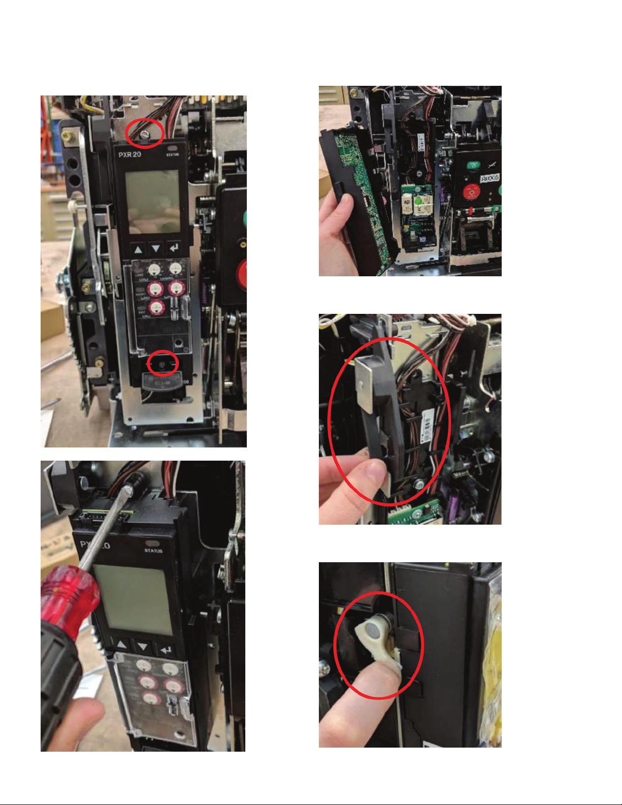
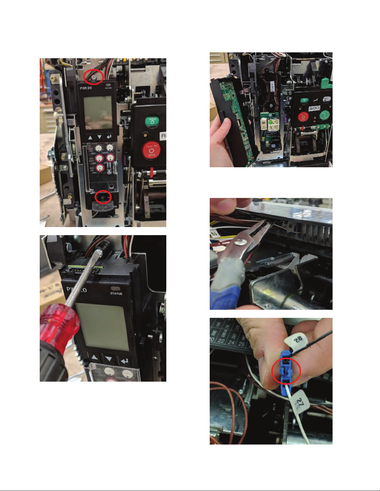
Tools/materials required
• Slotted/flathead screwdriver
• Phillips-head screwdriver
• Needle nose pliers or wire harness removal tool
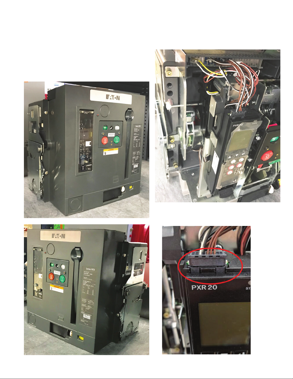
Kit parts identification
Inspect the kit upon receipt to verify all of the kit components
are available for the fieldwork:
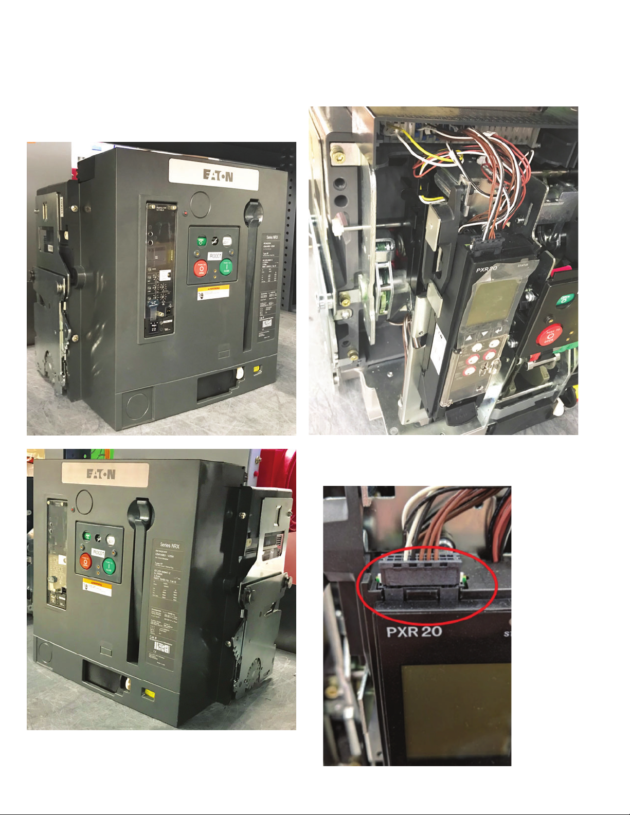
(A) PXR 20 or PXR 25 trip unit
(B) Instruction leaflet (this document)
(C) Tools required for installation (see above)
(D) PXR 25 Max Wiring Harness (only for PXR 25 upgrades)
(E) Instruction leaflet MN013003EN

3
Instruction Leaet IL019238EN
Effective July 2019
Series NRX breaker PXR trip unit
eld installation instructions
EATON www.eaton.com
Section 2:Trip unit replacement
This section is a guide for replacing a PXR 20 trip unit with a new
PXR 20 trip unit. If upgrading a PXR 20 to a PXR 25 trip unit,
please skip to “PXR 25 trip unit upgrade” on page 6.
1. Identify the breaker unit for trip unit replacement.
2. Remove the front cover by removing the four front cover screws
(positions shown by the arrows below). Note: The handle needs
to be pulled down and then the cover can be removed.
3. Make sure the breaker is discharged before proceeding to the
next steps. The picture below shows the product with the front
coverremoved.
4. Disconnect the trip unit from the breaker. Pinch the white tabs
on the side of the wire harness and pull the wire harness out of
the trip unit and set aside.

4
Instruction Leaet IL019238EN
Effective July 2019
Series NRX breaker PXR trip unit
eld installation instructions
EATON www.eaton.com
5. Use a flathead screwdriver to remove the top and bottom screws
from the trip unit. See picture below for location of the screws.
6. Remove the old trip unit from the breaker and set aside.
ote:N If working with the RF breaker, push in the trip unit interlock on the
side of the trip unit slot prior to removing the trip unit. See picture below.
ote:N If working with the NF breaker, engage the wire form interlock prior to
removing the trip unit.

5
Instruction Leaet IL019238EN
Effective July 2019
Series NRX breaker PXR trip unit
eld installation instructions
EATON www.eaton.com
7. Place the new trip unit into the slot while pushing on the trip
unit interlock (RF breaker) or the wire form interlock (NF breaker).
Make sure the screws are lined up with the proper holes and the
new trip unit snaps firmly into place.
8. Tighten the screw clockwise to secure trip unit in place.
9. Connect the wire harness to the new trip unit.
NOTICE
IF THE WORK BEING PERFORMED IS A DIRECT REPLACEMENT, THEN
THE EXISTING HARNESS WILL WORK. IF YOU ARE GOING FROM A
NON-MODBUS OPTION TO A MODBUS OPTION, THEN CHANGE THE
HARNESS. REFER TO THE PROCEDURE IN SECTION 3, STEP 8.
10. Place the cover back on the breaker. Secure and tighten the four
front cover screws. The replacement of a PXR 20 trip unit to a
new PXR 20 trip unit is complete.
Add the appropriate modification label as indicated in AppendixA
to the front cover to indicate the changes made to the breaker.

6
Instruction Leaet IL019238EN
Effective July 2019
Series NRX breaker PXR trip unit
eld installation instructions
EATON www.eaton.com
Section 3: PXR 25 trip unit upgrade
1. Identify the breaker unit for trip unit replacement.
2. Remove the front cover by removing the four front cover screws
(positions shown by the arrows below). Note: The handle needs
to be pulled down and then the cover can be removed.
3. Make sure the breaker is discharged before proceeding to the
next steps. The picture below shows the product with the front
coverremoved.
4. Disconnect the trip unit from the breaker. Pinch the white tabs
on the side of the wire harness and pull the wire harness out of
the trip unit and set aside.

7
Instruction Leaet IL019238EN
Effective July 2019
Series NRX breaker PXR trip unit
eld installation instructions
EATON www.eaton.com
5. Use a flathead screwdriver to remove the top and bottom screws
from the trip unit. See picture below for location of the screws.
6. Remove the old trip unit from the breaker and set aside.
7. Remove the PXR 20 wire harness. To remove each wire from
the terminal, squeeze the tab in between the two wires using
needle nose pliers. Set aside the PXR 20 wire harness.

8
Instruction Leaet IL019238EN
Effective July 2019
Series NRX breaker PXR trip unit
eld installation instructions
EATON www.eaton.com
8. Install the PXR 25 wire harness. Match the wire number to the
corresponding spot on the secondary connection. Make sure the
wires are installed in the correct orientation. Even numbers will
be on the top row, and odd numbers will be on the bottom row.
ote:N If working with the RF breaker, push in the trip unit interlock on the
side of the trip unit slot prior to removing the trip unit. See picture below.
ote:N If working with the NF breaker, engage the wire form interlock prior to
removing the trip unit. See picture below.

9
Instruction Leaet IL019238EN
Effective July 2019
Series NRX breaker PXR trip unit
eld installation instructions
EATON www.eaton.com
9. Place the new trip unit into the slot while pushing on the trip
unit interlock (RF breaker) or the wire form interlock (NF breaker).
Make sure the screws are lined up with the proper holes and the
trip unit snaps firmly into place.
10. Tighten the screw clockwise to secure trip unit in place.
11. Plug the PXR 25 wire harness into the PXR 25 trip unit.
12. The PXR 25 system requires that an Eaton External PT
Module must be installed in the switchgear enclosure. The
External PT Module must be wired up to the Eaton cassette
breaker secondary connectors and then routed to the Eaton
Series NRX breaker and associated internal PXR 25 trip unit.
The instructions on how to mount this external component are
shown in Eaton IL01301074E. Test the external unit to make sure
it is operating properly per the instructions provided with the kit.
13. Place the cover back on the breaker. Secure and tighten the
fourfront cover screws. The upgrade from a PXR 20 trip unit to a
PXR 25 trip unit is now complete.
Note: The handle needs to be pulled down to reinstall the
frontcover.
Add the appropriate modification label as indicated in AppendixA
to the front cover to indicate the changes made to the breaker.

10
Instruction Leaet IL019238EN
Effective July 2019
Series NRX breaker PXR trip unit
eld installation instructions
EATON www.eaton.com
Section 4:Testing/quality check
Test the product to make sure it is operating correctly before
returning the product to service. Mechanically operate the breaker
three times manually, including a charge, close, and open operation.
If possible, also use control power to electrically operate the
breaker three times, including a charge, close, and open operation.
Operate accessories (shunt trip or UVR) and/or any internal key
lock interlocks on the breaker. If any operational issues cannot be
resolved, contact your local Eaton salesperson for further support.
Perform functional trip unit testing via the trip unit itself or via the
Power Xpert Protection Manager software as shown in Instruction
Leaflet MN013003EN.
Appendix A: Label application details
Table 1. Modification list
INSTRUCTIONS: Peel off appropriate label and place on the breaker front cover.
Modification Style number Catalog number
PXR 25
PXR 25 global ground fault, arms, Modbus 65A3072G21 PXR25V000LGAMK
PXR 25 global with arms, Modbus 65A3072G22 PXR25V000LOAMK
PXR 25 global with ground fault, Modbus 65A3072G23 PXR25V000LGOMK
PXR 25 global with Modbus 65A3072G24 PXR25V000LOOMK
PXR 20
PXR 20 global ground fault, arms, Modbus 65A3072G25 PXR20V000LGAMK
PXR 20 global with ground fault, arms 65A3072G26 PXR20V000LGACK
PXR 20 global with ground fault, Modbus 65A3072G27 PXR20V000LGOMK
PXR 20 global with ground fault 65A3072G28 PXR20V000LGOCK
PXR 20 global with Modbus 65A3072G29 PXR20V000LOOMK
PXR 20 global 65A3072G30 PXR20V000LOOCK
PXR 20 global with arms, Modbus 65A3072G31 PXR20V000LOAMK
PXR 20 global with arms 65A3072G32 PXR20V000LOACK

11
Instruction Leaet IL019238EN
Effective July 2019
Series NRX breaker PXR trip unit
eld installation instructions
EATON www.eaton.com

Eaton
1000 Eaton Boulevard
Cleveland, OH 44122
United States
Eaton.com
© 2019 Eaton
All Rights Reserved
Printed in USA
Publication No. IL019238EN / Z22900
July 2019
Eaton is a registered trademark.
All other trademarks are property
of their respective owners.
Series NRX breaker PXR trip unit
eld installation instructions
Instruction Leaet IL019238EN
Effective July 2019
Other manuals for Series NRX
24
Table of contents
Other Eaton Circuit Breaker manuals

Eaton
Eaton PKE12 Series Manual

Eaton
Eaton VHI20-PKZ01 Manual

Eaton
Eaton PKE32/XTU-36-SOND533 Manual

Eaton
Eaton Ulusoy URING36 - LLF User manual

Eaton
Eaton CN13KN0 Manual

Eaton
Eaton MSC-D XTSE Series Manual

Eaton
Eaton NZM1-XFIU Manual

Eaton
Eaton DILM32-XRL-PI Manual

Eaton
Eaton Power Defense 32-NF Manual

Eaton
Eaton AEGIS AG II IT DN0 Series User manual

Eaton
Eaton DILM-XMV XTCEXML Series Manual

Eaton
Eaton B20B-VR Series User manual

Eaton
Eaton P-SOL60 Manual

Eaton
Eaton QSA63N1 Series Manual

Eaton
Eaton NZM3-XR Series Manual

Eaton
Eaton P1 /I2 Series Manual

Eaton
Eaton PKZ Series Manual

Eaton
Eaton TA602LD Manual

Eaton
Eaton ZB-XPLH Manual

Eaton
Eaton PKZMO-0,16/XTPRP16BC1 User manual