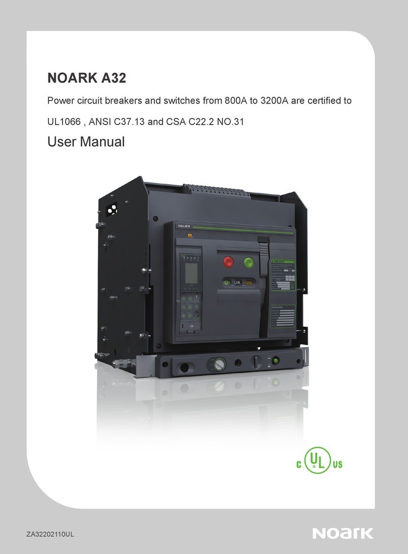
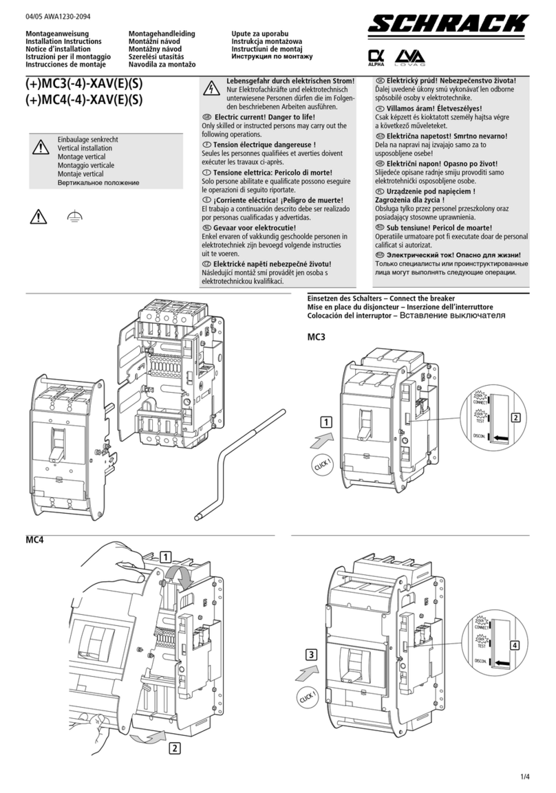
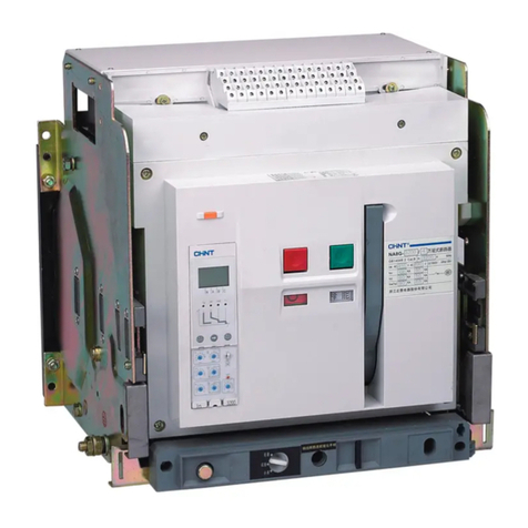
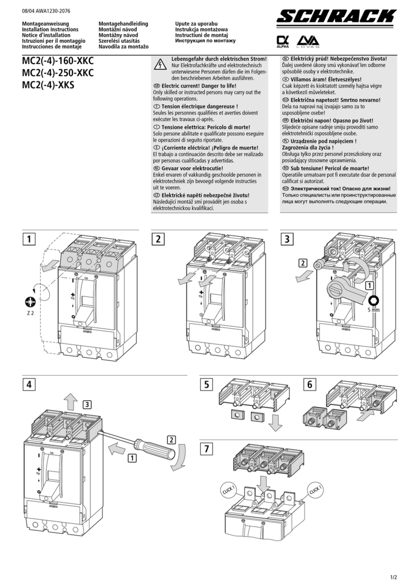
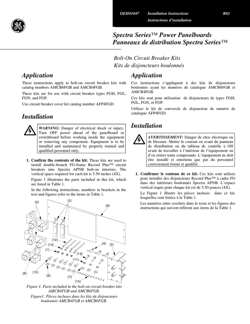
Noark A32 User manual

Air Circuit Breaker
Usage Manual
ZA32202209UL
NOARK A32
Power circuit breakers and switches from 800A to 3200A are certified to
UL1066 , ANSI C37.13 and CSA C22.2 NO.31
User Manual

Installation manual
Overview 01
Selection Guide 02
Product parameters 06
Environmental Conditions 07
Pckage identification 08
Storage 09
Necessary tools 10
Unpacking 11
Handling 13
Installation Dimension 16
Terminal Adjustment 36
Neutral Current Transformer 39
ELM10 41
Accesories 44
Conrtol ciruit wiring 50
Smart Unit Operating Instruction
Profile of SU 54
Main Menus 61
Menu 62
Overview of Functions 65
Appendix 66

User Manual 01
This device should be installed, operated, serviced and maintained only by professional personnel.
Noark Electric is not responsible for any consequences caused by non-compliance with this the manual.
After unpacking the product, check for any damage and the integrity of other items.
Do not install the product in inflammable, explosive, humid and condensing environment.
Do not install the product at places where gas medium can cause metal corrosion and insulation damage.
Connect the product to the proper power supply and standard wires.
Leave sufficient space and safe distance around the product.
Do not touch the conductive parts during operation.
Disconnect all the power sources during installation and maintenance.
Failure to follow the above instructions may result in equipment damage, personal injury or even death.
Environmental protection
To protect environment, this product and its components should be disposed properly as industrial waste upon
end of life; or delivered to recycling plant who will dismantle and recycle the product according to relevant
national regulations.
UL 1066、ANSI C37.13、ANSI C37.16、ANSI C37.17、ANSI C37.50,CSA C22.2 NO.31
UL file number: E502732
Codes and Standards
1
2
4
3
6
5
7910111213 8
141516
Overview
1. Brand
2. Opening push-button (O)
3. Closing push-button (I)
4. Manual spring charge handle
5. Nameplate
6. Closing ready indicator
9. Spring charged/discharged indicator
10. Rotary handle operation hole
C
h
a
r
g
e
d
Discharged
a) Spring charged
b) Spring discharged
a) ready
b) not ready
a) opening
b) closing
OFF
ON
OK
OK
7. Cassette position lock(manually
reset after injection)
8. Padlock
11. Main contact position indicator
12. Indicator for Disconnect, Test,Connect
position
13. Rotary handle
14. Smart Unit
15. Trip reset button
16. Control circuit wiring terminal

User Manual 03User Manual 02
Selection Guide
A 32 H 3 F H 800
I II III IV V VI VII
I
Noark UL1066 power circuit breakers
A: Power circuit breakers
ASD: Non-automatic switches
II Frame Size
32: 3200A
III Interrupting/short time withstand current
Q: 65kA, R: 85kA, H: 100kA
IV
Number of poles:
3– 3 Pole
4 – 4 Pole
VInstallation
F: Fixed ; D: withdrawable
VI
H: Horizontal ; V: Vertical
* 3200A only provided with vertical type.
* contact Noark sales for other configuration.
VII
Rated current:
800– 800A
1600 – 1600A
2000 – 2000A
2500 – 2500A
3200 – 3200A
Catalog designation for cassette
Catalog Designation for Auxiliary contact
Catalog Designation for Under voltage Trip
Catalog Designation for Motor Operator Device
Catalog Designation for Shunt Trip
Catalog Designation for Closing Release/Shunt Close
AX 12 N 44
I II III IV
I AX: Auxiliary contact
II 12: For 3200A PCB
III N: UL
IV
Contact configuration
44: 4NO+4NC, 66: 6NO+6NC
44C: 4NO/NC, 66C: 6NO/NC
SHT 12 N A
I II III IV
ISHT: Shunt trip release
SHTD: second shunt trip release
II 12: For 3200A PCB
III N: UL
IV Control voltage
A: 24-30VDC, B: 48-60VDC, C: 110-130VAC/DC, D: 208-240VAC/DC
XF 12 N A
I II III IV
I XF: Shunt close
II 12: For 3200A PCB
III N: UL
IV Control voltage
A: 24-30VDC, B: 48-60VDC, C: 110-130VAC/DC, D: 208-240VAC/DC
UVT 12 N A
I II III IV
I UVT: Under voltage trip
II 12: For 3200A PCB
III N: UL
IV Control voltage
A: 24VDC, B: 48VDC, C: 110 - 130VAC/DC, D: 208 - 240VAC/DC E: 380-415VAC
MD 12 N C
I II III IV
I MD: Motor operator Device
II 12: For 3200A PCB
III N: UL
IV Control voltage
A: 24-30VDC, B: 48-60VDC, C: 110-130VAC/DC, D: 208-240VAC/DC
Selection Guide
CAS 12 N 3 V 3200
I II III IV V VI
I CAS: Cassette
II Frame size
12: 3200A
III N: UL
IV
Pole
3: 3P
4: 4P
V
H: Horizontal
V: Vertical
* 3200A only available with vertical wiring.
VI
Rated current
1600: 800A, 1600A,
2500: 2000A, 2500A,
3200: 3200A
Catalog Designation for Trip unit
SU 30 N H A
I II III IV V
I SU: Smart unit
II Protection type
20: LI, 30: LSI, 40: LSIG
III N: UL
IV
Measurement type
M: Basic without measurement (LED display)
A: Ammeter (LCD display)
H: Harmonics (LCD display)
VControl voltage
A: 24VDC,C: 110-130VAC, D: 208-240VAC

User Manual 05User Manual 04
Catalog Designation for Phase barrier for withdrawable type
Catalog Designation for Door interlocks for withdrawable type
Catalog Designation for Mechanical Interlocks with cables
VPEC 12 N S
I II III IV
I VPEC: Door interlocks for withdrawable type
II 12: For 3200A PCB
III N: UL
IV P: Position interlock
S: Status interlock
IPA 12 N
I II III
I IPA: Mechanical Interlocks with cables
II 12: For 3200A PCB
III N: UL
DPS 12 N 2
I II III IV
I DPS: Phase barrier for withdrawable type
II 12: For 3200A PCB
III N: UL
IV 2: 2 pcs for 3P
3: 3 pcs for 4P
Selection Guide Selection Guide
Catalog Designation for Position indicator
EF 12 N
I II III
I EF: Position indicator
II 12: For 3200A PCB
III N: UL
Catalog Designation for OFF position keylock
KLK 12 N 1
I II III IV
I KLK: OFF position keylock
II 12: For 3200A PCB
III N: UL
IV 1: 1 lock 1 key, 2: 2 locks 1 key, 3: 3 locks 2 keys
Catalog Designation for Doorframes for fixed type
Catalog Designation for Doorframes for withdrawable type
CDP 12 N
I II III
I CDP: Doorframes for fixed type
II 12: For 3200A PCB
III N: UL
DDP 12 N
I II III
I DDP: Doorframes for withdrawable type
II 12: For 3200A PCB
III N: UL
Catalog Designation for Phase barrier for fixed type
PHS 12 N 2
I II III IV
I PHS: Phase barrier for fixed type
II 12: For 3200A PCB
III N: UL
IV 2: 2 pcs for 3P
3: 3 pcs for 4P
Catalog Designation for Pushbutton lock device
VBP 12 N
I II III
I VBP: Pushbutton lock device
II 12: For 3200A PCB
III N: UL
Catalog Designation for External current transformer for Neutral
NCT 12 N
Ⅰ Ⅱ Ⅲ
Ⅰ NCT: External Current transformer for Neutral
Ⅱ 12: For 3200A PCB
Ⅲ N: UL
Catalog Designation for Energy-Limiting Maintenance Switch (ELM Switch)
ELM 10
Ⅰ Ⅱ
Ⅰ ELM: Energy-Limiting Maintenance Switch
Ⅱ 10: For UL PCB
Catalog Designation for Lockable switch cover for ELM Switch
LSC 10
Ⅰ Ⅱ
Ⅰ LSC: Lockable switch cover for ELM Switch
Ⅱ 10: For UL PCB
Note: LSC10 is an optional unit, please comment if it is required when purchasing.

User Manual 07User Manual 06
Product parameters
Type A32Q A32R A32H ASD32Q ASD32R ASD32H
Pole 3P/4P 3P/4P
Installation Fixed/Withdrawable Fixed/Withdrawable
Rated current(A) 800/1600/2000/2500/3200 Fixed:800/1600/2000/2500
Withdrawable:800/1600/2000/2500/3200
Rated Maximum Valatge(V) 254/508/635 254/508/635
Frequency(Hz) 50/60 50/60
Interrupting rating at rated maximum voltage (kA)
254V 65 85 100 / / /
508V 65 85 100 / / /
635V 65 85 100 / / /
Short time withstand current (kA)
254V 65 85 100 65 85 100
508V 65 85 100 65 85 100
635V 65 85 100 65 85 100
operating time(ms) open <70 <70
close <40 <40
life cycle(time)
mechanical without maintenance 10000 10000 10000 10000 10000 10000
with maintenance / / / / / /
electrical without maintenance 6000 6000 6000 6000 6000 6000
with maintenance / / / / / /
Enclosure dimension
H×W×D(in/mm)
withdrawable
3P
21.65×23.62×18.11
(550×520×460)
Ventilation Area Top: 9092mm²
Bottom:9092mm²
21.65×23.62×18.11
(550×520×460)
Ventilation Area Top: 9092mm²
Bottom: 9092mm²
4P
21.65×25×18.11
(550×635×460)
Ventilation Area Top: 11963mm²
Bottom: 11963mm²
21.65×25×18.11
(550×635×460)
Ventilation Area Top: 11963mm²
Bottom: 11963mm²
fixed
3P 21.65×20.47×14.17
(550×520×360)
21.65×20.47×14.17
(550×520×360)
4P 21.65×25×14.17
(550×635×360)
21.65×25×14.17
(550×635×360)
Mounting type Rated current/A Power Consumption/W
Withdrawable 800 80
Withdrawable 1600 300
Withdrawable 2000 400
Withdrawable 2500 500
Withdrawable 3200 620
Fixed 800 50
Fixed 1600 200
Fixed 2000 250
Fixed 2500 300
Fixed 3200 430
A32 Bus bar recommendation
In
Vertical Horizontal
Qty Size(in) Size(mm) Qty Size(in) Size(mm)
800A 1 1/4×3 6.35×76.2 1 1/4×3 6.35×76.2
1600A 2 1/4×3 6.35×76.2 2 1/4×3 6.35×76.2
2000A 2 1/4×4 6.35×101.6 3 1/4×3 6.35×76.2
2500A 3 1/4×4 6.35×101.6 5 1/4×3 6.35×76.2
3200A 4 1/4×4 6.35×101.6
Recommended tighting torque is 40-50 N.m.
Note: These tables should be used as a general guideline only, the solution used should take into consideration the varieties of switchgear types and conditions.
Environmental Conditions
Ambient temperature
Altitude
Humidity
Rated
Current(A)
Temperature(℃)
<40 45 50 55 60 65 70
800 100% 100% 100% 100% 100% 100% 100%
1600 100% 100% 100% 100% 100% 100% 100%
2000 100% 100% 100% 100% 100% 100% 93%
2500 100% 95% 92% 88% 83% 80% 75%
3200 100% 95% 92% 88% 83% 80% 75%
Altitude(m)
<2000 2600 3900 4900
Rated Voltage(V) 1xUe 0.95xUe 0.8xUe 0.7xUe
Rated Current(A) 1xIn 0.99xIn 0.96xIn 0.94xIn
A32 Circuit breakers can operate in the following environmental conditions:
With M Smart Unit: -40℃~ 70℃;
With H Smart Unit: -20℃~ 70℃;
A32 Circuit breakers can operate at higher temperatures than the reference temperature 40℃,in this case,the derating coefficients
shown in the table must be applied.
A32 Circuit breakers do not undergo changes in rated performance up to 2000m.Beyond this altitude ,the derating coefficients shown in
the table must be applied.
The relative humidity does not exceed 85% at 40℃,the monthly average maximum of relative humidity in the wettest month does not
exceed 90%.
The effect of surface condensation caused by temperature changes on product performance should be taken into consideration.

User Manual 09User Manual 08
1PCS
A32
Conform standard:
UL 1066/ANSI C37.13
CSA C22.2 No.31
12345678912345679812345678912345679 8
A32H3DV3200
+UVT12NA
+XF12NA
+SHT12NA
NOARK Electrics (shanghai) Co.,Ltd
Power Circuit Breaker
+AX12ND66
+MD12NA
+SU30NHA
File E502732
1
1
A32
Conform standard:
UL 1066/ANSI C37.13
CSA C22.2 No.31
1 2 3 4 5 6 7 8 9 1 2 3 4 5 6 7 9 81 2 3 4 5 6 7 8 9 1 2 3 4 5 6 7 9 8
A32H3DV3200
+UVT12NA
+XF12NA
+SHT12NA
NOARK Electrics (shanghai) Co.,Ltd
Power Circuit Breaker
+AX12ND66
+MD12NA
+SU30NHA
File E502732

User Manual 11User Manual 10
installation bolt:Hex Cap Screws:7/16 in x 23
4in
Hex Cap Screws :
17
0.67(17)
7/16 in x 2 3
4in
in/mm
Withdrawable
7. Pull out the main breaker to maximum extent
Nameplate example
LOW VOLTAGE AC POWER CIRCUIT BREAKER
UL 1066/ANSI C37.13/CSA C22.2 No.31
Frame Size:3200A Frequency:50/60Hz
Rated Continuous Current: Poles:
Cat.
MFG.Date:
Serial No. : E510966
MADE IN CHINA
Rated Maximum Voltage(V)
Rated Short Circuit Current(kA)
Short-Time Withstand Current
(kA,0.5s)
254 508 635
Instruction Manual:
5. Press and hold pull out button
6. Pull out the main breaker
Rotate handle indicator
to disconnect position
Connected
Test
Disconnected

User Manual 13User Manual 12
Unpacking
800A/1600A
net weight
gross weight
net weight
gross weight
133/60
176/80
126/57
170/77
power circuit breaker
non-automatic switch
net weight
gross weight
net weight
gross weight
123/56
163/74
117/53
156/71
power circuit breaker
non-automatic switch
2000A/2500A
800A/1600A
net weight
gross weight
net weight
gross weight
133/60
176/80
126/57
170/77
power circuit breaker
non-automatic switch
net weight
gross weight
net weight
gross weight
123/56
163/74
117/53
156/71
power circuit breaker
non-automatic switch
2000A/2500A
unit : lb/kg
User Manual 13User Manual 12
Handling
800A/1600A
net weight
gross weight
net weight
gross weight
147/67
191/87
141/64
184/84
power circuit breaker
non-automatic switch
net weight
gross weight
net weight
gross weight
133/60
176/80
126/57
170/77
power circuit breaker
non-automatic switch
net weight
gross weight
net weight
gross weight
123/56
163/74
117/53
156/71
power circuit breaker
non-automatic switch
net weight
gross weight
net weight
gross weight
264/120
308/140
258/117
301/137
power circuit breaker
non-automatic switch
net weight
gross weight
net weight
gross weight
245/111
289/131
239/208
282/128
power circuit breaker
non-automatic switch
net weight
gross weight
net weight
gross weight
215/97
257/117
208/95
250/114
power circuit breaker
non-automatic switch
net weight
gross weight
net weight
gross weight
185/84
224/102
179/81
217/99
power circuit breaker
non-automatic switch
net weight
gross weight
net weight
gross weight
166/75
205/93
159/72
198/90
power circuit breaker
non-automatic switch
net weight
gross weight
net weight
gross weight
153/70
192/87
147/67
185/84
power circuit breaker
non-automatic switch
net weight
gross weight
net weight
gross weight
331/150
383/174
324/147
377/171
power circuit breaker
non-automatic switch
net weight
gross weight
net weight
gross weight
309/140
361/164
300/136
352/160
power circuit breaker
non-automatic switch
net weight
gross weight
net weight
gross weight
260/118
311/141
253/115
304/138
power circuit breaker
non-automatic switch
2000A/2500A 3200A
unit : lb/kg

User Manual 15User Manual 14
Handling

User Manual 17User Manual 16
800A/1600A 3P
Vertical installation
Fixed type
in/mm
800A/1600A 4P
Vertical installation
Fixed type
in/mm
18 19
固定式 800A/1600A 3P 垂直安装
in/mm
3.58(91)
3.17(80.5)
8.64(219.5)
14.61(371)
8× (6)
0.24
12× 130.51
10.55(268)
12.24(311)
12.91(328)
4.53(115)
0.59(15)
4.53(115)
10.06(255.5)
0.98(25)
Max 2.36(60)
overlap
F
8.46(215)
7.95(202) 7.95(202)
6.06(154) 6.06(154)
8.46(215)
5.08(129)
0.47(12)
5.91(150)3.17(80.5)
3.46(88)
5.24(133)
0.63(16)
0.88(21.5)
1.77(45)
6.44(163.5)
5.08(129)
9(228.5)
F
安装尺寸
框架断路器
Datum X
Datum Y
18 19
固定式 800A/1600A 4P 垂直安装
in/mm
3.58(91)
3.17(80.5)
8.64(219.5)
12.99(330)
6.06(154) 6.06(154)
8.46(215)
5.08(129)
6.44(163.5)
5.08(129)
9(228.5)
F
14.61(371)
8× (6)
0.24
10.55(268)
12.24(311)
12.91(328)
12.48(317) 7.95(202)
0.47(12)
5.91(150)
3.17(80.5)
16× 130.51
4.53(115)
0.59(15)
4.53(115) 4.53(115)
10.06(255.5)
0.98(25)
Max 2.36(60)
overlap
F
3.46(88)
5.24(133)
0.63(16)
0.88(21.5)
1.77(45)
安装尺寸
框架断路器
Datum Y
Datum X

User Manual 19User Manual 18
800A/1600A 3P
Horizontal installation
Fixed type
in/mm
800A/1600A 4P
Horizontal installation
Fixed type
in/mm
20 21
固定式 800A/1600A 3P 水平安装
in/mm
3.58(91)
3.17(80.5)
8.64(219.5)
6.06(154) 6.06(154)
8.46(215)8.46(215)
5.08(129)
6.44(163.5)
5.08(129)
9(228.5)
F
F
14.61(371)
8× (6)
0.24
10.55(268)
12.24(311)
12.91(328)
7.95(202) 7.95(202)
0.47(12)
5.91(150)
3.17(80.5)
12× 130.51
4.53(115)
0.59(15)
4.53(115)
10.06(255.5)
0.94(25)
Max 2.36(60)
overlap
F
3.46(88)
5.24(133)2.36(60)
0.88(21.5)
1.77(45)
安装尺寸
框架断路器
Datum X
Datum Y
20 21
固定式 800A/1600A 4P 水平安装
in/mm
16× 13
0.51
4.53(115)
0.59(15)
4.53(115) 4.53(115)
10.06(255.5)
0.94(25)
Max 2.36(60)
overlap
F
3.46(88)
5.24(133)2.36(60)
0.88(21.5)
1.77(45)
F
14.61(371)
8× (6)
0.24
10.55(268)
12.24(311)
12.91(328)
12.48(317) 7.95(202)
0.47(12)
5.91(150)3.17(80.5)
3.58(91)
3.17(80.5)
8.64(219.5)
6.06(154) 6.06(154)
8.46(215)12.99(330)
5.08(129)
6.44(163.5)
5.08(129)
9(228.5)
F
安装尺寸
框架断路器
Datum X
Datum Y

User Manual 21User Manual 20
2000A/2500A 3P
Vertical installation
Fixed type
in/mm
2000A/2500A 4P
Vertical installation
Fixed type
in/mm
22 23
固定式 2000A/2500A 3P 垂直安装
in/mm
3.58(91)
3.17(80.5)
8.64(219.5)
6.06(154) 6.06(154)
8.46(215)8.46(215)
5.08(129)
6.44(163.5)
5.08(129)
9(228.5)
F
F
14.61(371)
8× (6)
0.24
10.55(268)
12.24(311)
12.91(328)
7.95(202) 7.95(202)
0.47(12)
5.91(150)3.17(80.5)
24× 130.51
4.53(115)
0.69(17.5)
9.53(242)
4.53(115)
0.63(16)
Max 3.31(84)
overlap
0.79(20)
5.24(133)
3.46(88)
0.88(21.5)
1.77(45)
1.77(45)
安装尺寸
框架断路器
Datum X
Datum Y
22 23
固定式 2000A/2500A 4P 垂直安装
in/mm
3.58(91)
14.61(371)
4.53(115)
0.79(20)
F
4.53(115) 4.53(115)
9.53(242) 1.77(45)
0.69(17.5)
1.77(45) 5.24(133)
3.46(88)0.88(21.5)
0.63(16)
Max overlap 3.31(84)
12.48(317) 7.95(202)
8× 0.24 (6)
32×0.51 13
12.24(311)
10.55(268)
12.91(328)
F3.17(80.5)
3.17(80.5) 5.91(150)
0.47(12)
6.06(154)
12.99(330) 8.46(215)
5.08(129)
9(228.5)6.44(163.5)
5.08(129)
6.06(154)
8.64(219.5)
安装尺寸
框架断路器
Datum Y
Datum X

User Manual 23User Manual 22
2000A/2500A 3P
Horizontal installation
Fixed type
in/mm
2000A/2500A 4P
Horizontal installation
Fixed type
in/mm
24 25
固定式 2000A/2500A 3P 水平安装
in/mm
3.58(91)
F
F
3.17(80.5)
6.06(154)
8.46(215) 8.46(215)
5.08(129)
9(228.5)6.44(163.5)
5.08(129)
6.06(154)
8.64(219.5)
14.61(371)
7.95(202) 7.95(202)
8× 0.24 (6)
12.24(311)
10.55(268)
12.91(328)
3.17(80.5) 5.91(150)
0.47(12)
4.53(115)
0.79(20)
F
4.53(115)
9.53(242) 1.77(45)
0.69(17.5)1.77(45)
1.77(45)
5.24(133)
3.46(88)
0.88(21.5)
2.36(60)
Max overlap 3.31(84)
24× 0.51 13
安装尺寸
框架断路器
Datum X
Datum Y
24 25
固定式 2000A/2500A 4P 水平安装
in/mm
3.58(91)
14.61(371)
12.48(317) 7.95(202)
8× 0.24 (6)
12.24(311)
10.55(268)
12.91(328)
F
F
3.17(80.5)
3.17(80.5) 5.91(150)
0.47(12)
6.06(154)
12.99(330) 8.46(215)
5.08(129)
9(228.5)6.44(163.5)
5.08(129)
6.06(154)
8.64(219.5)
4.53(115) 4.53(115)
0.79(20)
F
4.53(115)
9.53(242) 1.77(45)
0.69(17.5)1.77(45)
1.77(45)
5.24(133)
3.46(88)
0.88(21.5)
2.36(60)
Max overlap 3.31(84)
24× 0.51 13
安装尺寸
框架断路器
Datum X
Datum Y

User Manual 25User Manual 24
Fixed type
3200A 3P
Vertical installation
in/mm
3200A 4P
Vertical installation
Fixed type
in/mm
26
固定式 3200A 3P 垂直安装
in/mm
3.58(91)
F3.17(80.5)
6.06(154)
8.50(216) 8.50(216)
5.08(129)
9.00(228.5)6.44(163.5)
5.08(129)
6.06(154)
8.64(219.5)
F
14.61(371)
7.99(203) 7.99(203)
8× 0.24 (6)
12.24(311)
10.55(268)
12.91(328)
3.17(80.5) 5.91(150)
0.47(12)
4.53(115)
4.53(115)
0.79(20)
0.79(20)
F
4.53(115)
4.53(115)
11.30(287)1.77(45)
1.77(45)
0.30(7.5)
3.35(85)
0.33(8.5) 0.33(8.5)
1.04(26.4)
0.25(6.4)
6.02(153)
Max overlap 3.46(88)
48×0.51 13
安装尺寸
框架断路器
Datum X
Datum Y
C
M
Y
CM
MY
CY
CMY
K
27
固定式 3200A 4P 垂直安装
in/mm
3.58(91)
F3.17(80.5)
6.06(154)
13.03(331) 8.50(216)
5.08(129)
9.00(228.5)
6.44(163.5)
5.08(129)
6.06(154)
8.64(219.5)
F
14.61(371)
12.52(318) 7.99(203)
8× 0.24 (6)
12.24(311)
10.55(268)
12.91(328)
3.17(80.5) 5.91(150)
0.47(12)
4.53(115)
4.53(115)
0.79(20)
0.79(20)
F
4.53(115)
4.53(115)
4.53(115)
4.53(115)
11.30(287)1.77(45)
1.77(45)
0.30(7.5)
3.35(85)
0.33(8.5) 0.33(8.5)
1.04(26.4)
0.25(6.4)
6.02(153)
Max overlap 3.46(88)
64×0.51 13
安装尺寸
框架断路器
Datum X
Datum Y
C
M
Y
CM
MY
CY
CMY
K

User Manual 27User Manual 26
800A/1600A 3P
Vertical installation
Withdrawable type
in/mm
800A/1600A 4P
Vertical installation
Withdrawable type
in/mm
28 29
抽屉式 800A/1600A 3P 垂直安装
in/mm
3.86(98)
4.37(111)
6.14(156) 12.38(314.5)
F
F
F
6.40(162.5) 6.40(162.5)
0.43(11)
0.43 11
0.67(17)
6.89(175)
14.61(371)
8× 0.24 (6)
14.88(378)
6.10(155)
1.85(47)
0.85(21.5)
10.55(268)
5.79(147)
12.91(328)
6.06(154)
8.6(218.5) 8.6(218.5)
5.09(129)
9.07(230.5)
7.85(199.5)
7.64(194)
6.89(157)
5.09(129)
6.06(154)
4.53(115)
0.47(12)
4.53(115)
2.28(58)
1.77(45)
0.85(21.5)
1.77(45)13.94(354)
5.59(142)
3.46(88)
0.89(22.5)
Max overlap 3.54(90)
24× 0.51 13
安装尺寸
框架断路器
(Disconnection position)
(Connection position)
Datum Y
panel perforating size
Circuit breaker
installation board
28 29
抽屉式 800A/1600A 4P 垂直安装
in/mm
3.86(98)
4.37(111)
6.14(156) 12.38(314.5)
F
F
10.93(277.5) 6.40(162.5)
0.43(11)
0.43 11
0.67(17)
6.89(175)
14.61(371)
8× 0.24 (6)
14.88(378)
6.10(155)
1.85(47)
0.85(21.5)
10.55(268)
5.79(147)
12.91(328)
6.06(154)
13.13(333.5) 8.6(218.5)
5.09(129)
9.07(230.5)
7.85(199.5)
7.64(194)
6.89(157)
5.09(129)
6.06(154)
F
4.53(115)
0.47(12)
4.53(115) 4.53(115)
2.28(58)
1.77(45)
0.85(21.5)
1.77(45)13.94(354)
5.59(142)
3.46(88)
0.89(22.5)
Max overlap 3.54(90)
32× 0.51 13
安装尺寸
框架断路器
(Disconnection position)
(Connection position)
Datum Y
panel perforating size
Circuit breaker
installation board

User Manual 29User Manual 28
800A/1600A 4P
Horizontal installation
Withdrawable type
in/mm
800A/1600A 3P
Horizontal installation
Withdrawable type
in/mm
30 31
抽屉式 800A/1600A 3P 水平安装
in/mm
3.86(98)
4.37(111)
6.14(156) 12.38(314.5)
F
F
6.40(162.5) 6.40(162.5)
0.43(11)
0.43 11
0.67(17)
6.89(175)
14.61(371)
8× 0.24 (6)
14.88(378)
6.10(155)
1.85(47)
0.85(21.5)
10.55(268)
5.79(147)
12.91(328)
6.06(154)
8.6(218.5) 8.6(218.5)
5.09(129)
9.07(230.5)
7.85(199.5)
7.64(194)
6.89(157)
5.09(129)
6.06(154)
F
4.53(115)
0.47(12)
4.53(115)
4.61(117)
1.77(45)
1.77(45)
0.85(21.5)
1.77(45)
13.94(354)
5.59(142)
3.46(88)
0.89(22.5)
Max overlap 3.54(90)
24× 0.51 13
安装尺寸
框架断路器
(Disconnection position)
(Connection position)
Datum Y
Circuit breaker
installation board
panel perforating size
30 31
抽屉式 800A/1600A 4P 水平安装
in/mm
3.86(98)
4.37(111)
6.14(156) 12.38(314.5)
F
F
10.93(277.5) 6.40(162.5)
0.43(11)
0.43 11
0.67(17)
6.89(175)
14.61(371)
8× 0.24 (6)
14.88(378)
6.10(155)
1.85(47)
0.85(21.5)
10.55(268)
5.79(147)
12.91(328) 6.06(154)
13.13(333.5) 8.6(218.5)
5.09(129)
9.07(230.5)
7.85(199.5)
7.64(194)
6.89(157)
5.09(129)
6.06(154)
F
4.53(115)
0.47(12)
4.53(115) 4.53(115)
4.61(117)
1.77(45)
1.77(45)
0.85(21.5)
1.77(45)
13.94(354)
5.59(142)
3.46(88)
0.89(22.5)
Max overlap 3.54(90)
32× 0.51 13
安装尺寸
框架断路器
Datum Y
Circuit breaker
installation board
panel perforating size
(Disconnection position)
(Connection position)

User Manual 31User Manual 30
2000A/2500A 3P
Vertical installation
Withdrawable type
in/mm
2000A/2500A 4P
Vertical installation
Withdrawable type
in/mm
32 33
抽屉式 2000A/2500A 3P 垂直安装
in/mm
3.86(98)
4.37(111)
6.14(156) 12.38(314.5)
F
F
6.40(162.5) 6.40(162.5)
0.43(11)
0.43 11
0.67(17)
6.89(175)
14.61(371)
8× 0.24 (6)
14.88(378)
6.10(155)
1.85(47)
0.85(21.5)
10.55(268)
5.79(147)
12.91(328)
6.06(154)
8.6(218.5) 8.6(218.5)
5.09(129)
9.07(230.5)
7.85(199.5)
7.64(194)
6.89(157)
5.09(129)
6.06(154)
F
4.53(115)4.53(115)
1.77(45)
0.25(6.5)
1.2(30.5)
0.85(21.5)
2.28(58)
1.77(45)13.94(354)
5.59(142)
3.46(88)
0.89(22.5)
Max overlap 3.54(90)
48× 0.51 13
安装尺寸
框架断路器
(Disconnection position)
(Connection position)
Datum Y
Circuit breaker
installation board
panel perforating size
32 33
抽屉式 2000A/2500A 4P 垂直安装
in/mm
3.86(98)
4.37(111)
6.14(156)
0.43(11)
0.67(17)
6.89(175)
14.88(378)
5.79(147)
1.85(47)
10.55(268)
0.85(21.5)
5.09(129) 5.09(129)
9.07(230.5)6.89(157)
7.64(194)
7.85(199.5)
3.46(88)
5.59(142)
1.77(45)
2.28(58)
0.85(21.5)
0.89(22.5)
1.77(45)13.94(354)
64× 0.51 13
F
6.10(155)
10.93(277.5) 6.40(162.5)
0.43 11
12.38(314.5)
14.61(371)
4.53(115)
0.25(6.5)
1.2(30.5)
4.53(115) 4.53(115)
6.06(154) 6.06(154)
12.91(328)
13.13(333.5) 8.6(218.5)
3.54(90)overlap
Max
8× 0.24 (6)
F
F
安装尺寸
框架断路器
Datum Y
Circuit breaker
installation board
panel perforating size
(Disconnection position)
(Connection position)

User Manual 33User Manual 32
2000A/2500A 4P
Horizontal installation
Withdrawable type
in/mm
2000A/2500A 3P
Horizontal installation
Withdrawable type
in/mm
34 35
抽屉式 2000A/2500A 3P 水平安装
in/mm
3.86(98)
4.37(111)
6.14(156)
0.43(11)
0.67(17)
6.89(175)
6.40(162.5) 6.40(162.5)
0.43 11
12.38(314.5)
F
F
14.88(378)
5.79(147)
1.85(47)
10.55(268)
0.85(21.5)
5.09(129) 5.09(129)
9.07(230.5)6.89(157)
7.64(194)
7.85(199.5)
6.10(155)
14.61(371)
6.06(154) 6.06(154)
12.91(328)
8.6(218.5) 8.6(218.5)
8× 0.24 (6)
3.46(88)
5.59(142)
1.77(45)
1.77(45)
4.61(117)
0.85(21.5)
0.89(22.5)
1.77(45)13.94(354)
48× 0.51 13
F
4.53(115)
0.25(6.5)
1.2(30.5)
4.53(115)
3.54(90)overlap
Max
安装尺寸
框架断路器
Datum Y
Circuit breaker
installation board
panel perforating size
34 35
抽屉式 2000A/2500A 4P 水平安装
in/mm
3.86(98)
4.37(111)
6.14(156)
0.43(11)
0.67(17)
6.89(175)
10.93(277.5) 6.40(162.5)
0.43 11
12.38(314.5)
F
F
14.88(378)
5.79(147)
1.85(47)
10.55(268)
0.85(21.5)
5.09(129) 5.09(129)
9.07(230.5)6.89(157)
7.64(194)
7.85(199.5)
6.10(155)
14.61(371)
6.06(154) 6.06(154)
12.91(328)
13.13(333.5) 8.6(218.5)
8× 0.24 (6)
3.46(88)
5.59(142)
1.77(45)
1.77(45)
4.61(117)
0.85(21.5)
0.89(22.5)
1.77(45)13.94(354)
64× 0.51 13
F
4.53(115) 4.53(115)
0.25(6.5)
1.2(30.5)
4.53(115)
3.54(90)overlap
Max
安装尺寸
框架断路器
Datum Y
Circuit breaker
installation board
panel perforating size

User Manual 35User Manual 34
Withdrawable type
3200A 3P
Vertical installation
in/mm
3200A 4P
Vertical insatallation
Withdrawable type
in/mm
36
抽屉式 3200A 3P 垂直安装
in/mm
3.86(98)
4.25(108)
6.02(153)
0.43(11)
0.67(17)
6.89(175)
6.40(162.5) 6.40(162.5)
0.43 11
12.38(314.5)
F
F
14.88(378)
5.79(147)
1.85(47)
10.55(268)
0.85(21.5)
5.08(129) 5.08(129)
9.04(229.5)
6.22(158)
7.68(195)
7.89(200.5)
6.10(155)
14.61(371)
6.06(154) 6.06(154)
12.91(328)
4.35(115)
4.35(115) 4.35(115)
0.59(15) 0.59(15)
4.35(115)
1.04(26.4)
0.25(6.4)
8.56(217.5) 8.56(217.5)
8× 0.24 (6)
5.98(152)2.36(60)
0.79(20)
1.85(47)
0.79(20)
1.57(40)
72×0.51 13
16.28(413.5)
3.94(100)
F
3.27(83)overlap
Max
安装尺寸
框架断路器
Datum Y
Circuit breaker
installation board
panel perforating size
(Disconnection position)
(Connection position)
C
M
Y
CM
MY
CY
CMY
K
37
抽屉式 3200A 4P 垂直安装
in/mm
3.86(98)
4.25(108)
6.02(153)
0.43(11)
0.67(17)
6.89(175)
10.93(277.5) 6.40(162.5)
0.43 11
12.38(314.5)
F
F
14.88(378)
5.79(147)
1.85(47)
10.55(268)
0.85(21.5)
5.08(129) 5.08(129)
9.23(234.5)6.22(158)
7.68(195)
7.89(200.5)
6.10(155)
14.61(371) 6.06(154) 6.06(154)
12.91(328)
13.09(332.5) 8.56(217.5)
8× 0.24 (6)
4.35(115)
4.35(115) 4.35(115) 4.35(115)
4.35(115) 4.35(115)
0.59(150) 0.59(150)
1.04(26.4)
0.25(6.4)
5.98(152)
2.36(60)
0.79(20)
1.85(47)
0.79(20)
1.57(40)
96×0.51 13
16.28(413.5)
3.94(100)
F
3.27(83)overlap
Max
安装尺寸
框架断路器
(Disconnection position)
(Connection position)
Datum Y
Circuit breaker
installation board
panel perforating size
Other manuals for A32
1
Table of contents
Other Noark Circuit Breaker manuals

