manuals.online logo
Brands
  1. Home
  2. •
  3. Brands
  4. •
  5. GE
  6. •
  7. Circuit Breaker
  8. •
  9. GE POWER BREAK MICRO-VERSATRIP E39ME20 User manual

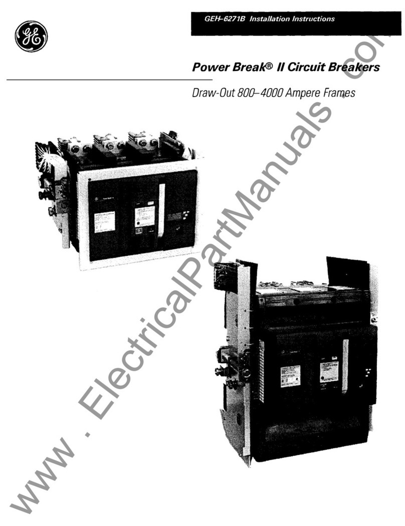
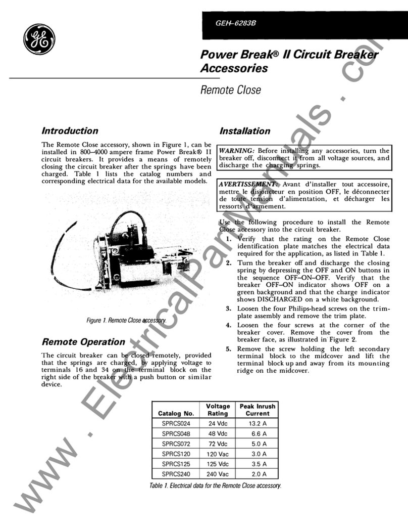
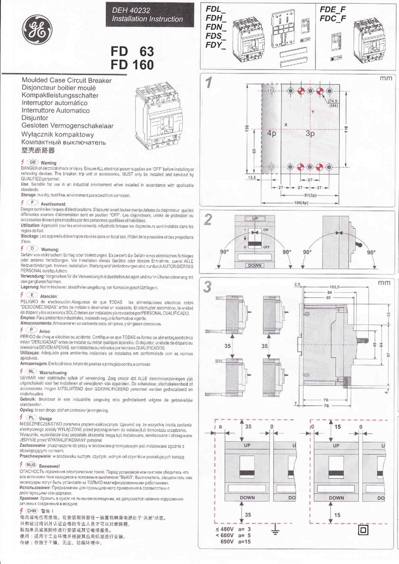
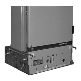
GE POWER BREAK MICRO-VERSATRIP E39ME20 User manual

GEH
4656
ii
POWFD
RDF
AK
instructions
*
DC
Rating
Appiies
to
MagneTrip
Only
.
Circuit
Breakers
2500
-
4000
A
Frames
600
Vac
,
250
Vdc
*
m
»
~
n
'
i
/
•
•
'
;
:
feii
,
“
<
NV
-
w
\
r
"
/
'
is
s
>
v
~
<
iba
_
,
.
.
.
.
“
»
r
'
-
ism
•
•
-
.
V
ammsmmgzmm
s
'
\
i
r
~
-
C
u
G
C
M
C
D
uun
A L
I
c
L
t
.
u
i
niu
t
Courtesy of NationalSwitchgear.com
Table
of
Contents
CONTENTS
PAGE
OPERATING
FEATURES
Key
to
Features
Sequence
of
Operation
OPERATING
INSTRUCTIONS
Manually
Operated
Devices
Application
Data
Wiring
Diagrams
Electrically
Operated
Devices
Operational
Data
Wiring
Diagrams
—
Power
Sources
,
ac
Power
Sources
,
dc
Wiring
for
Remote
Operation
TRIP
UNIT
AND
SETTING
Micro
-
VersaTrip
®
MagneTrip
ACCESSORIES
Circuit
Breaker
Accessory
Lead
Color
Code
Optional
Features
INSTRUCTION
MANUALS
3
3
4
4
4
5
5
6
6
6
7
,
8
,
9
9
10
10
10
2
Courtesy of NationalSwitchgear.com
®
IP
,
i
am
i
"
4
©
•
M
©
g
i
1
m
x
i
~~
~
i
LA
]
f
N
\
0
Power
Break
Jii
&
[
•
»
1
*
ar
SF
i
;
O
PowerBreak
r
!
i
:
!
B
|
LBJ
D
i
!
A
T
S
t
F
!
T
?
HM
fo
c
'
i
-
a
M
3
a
.
c
j
,
i
*
TFT
KtJ
'
i
m
i
4
?
iM
s
S
i
f
!
D
»
-
/
£
t
:
'
2
B
H
3
!
«
•
il
If
£
Si
E
jJ
}
J
-
v
c
h
1
,
•
I
ti
F
JSCOi
6
:
^
i
.
U
i
.
f
I
l
,
l
:
£
a
UJ
lit
Hi
cl
«
:
*
iKf
H
i
rm
I
v
*
»
5
'
•
j
M
i
•
•
FIGURE
1
2500
A
—
MANUAL
MiUKU
-
VfcHSATRlP
®
FIGURE
2
2500
A
—
ELECTRICAL
MICRO
-
VERSATRIP
®
-
FRONT
-
CONNECTED
KEY
TO
FEATURES
:
<
£
>
«
A
r
»
rJ
i
I
r
\
*
i
luioaiui
Manual
:
ON
—
Red
;
Charged
—
Yellow
;
Electrical
:
ON
—
Red
;
Charged
—
Yellow
;
OFF
—
Green
B
-
“
ON
”
Button
C
-
“
OFF
”
Button
D
-
Manual
Charging
Handle
E
-
Mechanism
Indicator
—
Manual
CHG
—
Yellow
;
O
—
White
F
-
Lockable
Manual
Charge
Engagement
Button
G
~
Terminal
Board
(
MOM
Drive
Unit
)
H
-
Cover
Escutcheon
J
-
Removable
Protective
Window
(
Micro
-
VersaTrip
®
Only
)
K
-
Programmer
Terminal
Board
(
Micro
-
VersaTrip
®
Oniy
)
L
-
CT
Tap
Setting
Indication
(
Micro
-
VersaTrip
®
Only
)
M
-
Cover
Mounting
Screws
(
4
)
;
(
2
)
under
cover
escutcheon
)
i
*
#
•
©
e
N
'
~
;
;
I
'
5
Pow
«
8
!
f
ai
.
,
;
;
.
1
:
\
o
>
-
I
r
o
i
_
_
‘
r
n
,
1
”
T
~
FIGURE
3
4000
A
—
MANUAL
MAGNETRIP
r
SEQUENCE
OF
OPERATION
e
r
~
TABLE
1
Main
Breaker
Contacts
Condition
Of
Charging
Springs
Permissible
Operating
Function
indicators
Manual
Electrical
E
AA
OFF
O
OFF
Open
Discharged
Mechanism
May
Be
Charged
Contacts
May
Be
Closed
Do
Not
Open
Or
Trip
From
This
Stage
OFF
CHG
CHARGED
Open
Charged
ON
O
ON
Closed
Discharged
Contacts
May
Be
Opened
3
Courtesy of NationalSwitchgear.com
dill
iy
III
MANUALLY
OPERATED
DEVICES
CAUTION
:
^
^ ^
/
J
141
^
^
^
4
^
^
^
v
#
A
^
X
A
<
*
J
4
^
M
I
A
A
I
«
A
4
A
«
-
*
-
I
A
X
A
Lh
11
icoc
UUIIUIUUIIO
muDi
ut
?
ouritjui
^
u
IU
umu
^
me
iaiun
before
repeating
the
charging
cycle
.
Failure
to
do
so
may
result
in
equipment
damage
.
B
.
To
Close
the
Breaker
1
.
Locally
—
Depress
the
ON
Button
on
the
breaker
escutcheon
(
Also
see
Limited
Ciose
Access
—
Accessory
)
O
L
)
/\
rv
>
I
«
f
/
^
l
—
!
«
4
U
/
>
A A
/
M
*
I
<
AI
A
«
I
«
^
A
A
I
A
rioiiluicny
—
\
wpuuu
;
LI
i
^
iyiz
-
c
me
auucodui
y
uiuon
ly
ouie
*
noid
.
Do
not
repeatedly
trip
the
device
from
the
charge
stage
as
equip
-
ment
damage
may
result
.
A
^
ik
M
Bf
M
T
1
«
A
kl
A
A
4
«
A
M
A
MM
OlAafaMJiaA
M
.
iu
vnaiyq
me
mcunaiiioiii
opiiiiyo
1
Charno
tho
maohaniem
K
\/
rr
\
tatinn
tha
nnorotinn
hanHIo
1
OH
0
I
•
v
/
l
IUI
^
V
U
IV
I
I
IWI
IUI
MWI
II
K
/
J
I
ViUlll
INj
II
IV
V
^
/
VI
Uill
V
IUI
I
VIV
I
U
\
S
counter
-
clockwise
(
until
the
handle
stops
)
.
Rotate
the
handle
clockwise
back
to
the
home
position
.
Repeat
this
cycle
two
(
2
)
more
times
.
THIS
OPERATION
WILL
NOT
TURN
THE
BREAKER
“
ON
”
—
CLOSE
CONTACTS
.
The
indicator
will
read
“
CHARGE
”
.
2
.
If
the
breaker
latch
is
held
tripped
by
any
of
the
following
A
.
A
.
A
.
•
«
-
»
M
.
M
t
»
»
^
LA
»
AA
«
«
.
A
.
LA
kA
>
«
AA
aA
ftk
kA
Ak
k
k
kill
AJ
4
k
LA
4
A
A
Ak
A
X
LA
kA
AI
ciuoessuriys
>
,
me
meuiicunsni
spinlys
win
uisericuye
eu
me
enu
of
the
charging
stroke
and
the
breaker
will
revert
to
the
dis
-
charged
“
OFF
”
condition
.
Kirk
lock
or
padlock
devices
in
locked
“
OFF
”
condition
.
Drawout
interlock
with
carriage
in
any
position
except
“
TEST
”
or
“
ENGAGED
”
.
Bell
alarm
lockout
not
reset
after
overcurrent
lockout
.
Undervoltage
release
device
not
energized
.
C
.
To
Open
the
Breaker
1
.
Locally
—
Depress
the
“
PUSH
OFF
”
button
on
the
breaker
/
N
J
*
\
I
|
4
AL
A
A
A
COUUIUI
ICUI
I
.
2
.
Remotely
—
(
Option
)
—
Energize
an
accessory
shunt
trip
or
de
-
energize
an
accessory
undervoltage
release
device
.
APPLICATION
DATA
—
Catalog
Numbers
TSXCC
12
B
,
TSXCC
14
B
,
TSXCC
08
B
—
V
/
IU
9
U
ly
OUICI
IUIU
TA
Dl
C
A
lADi
-
t
.
£
close
boienoid
*
Maximum
Clncinn
Timo
WWW
>
W
(
Seconds
)
Maximum
Hnoratinn
Timo
W
*
AJ
W
(
Seconds
)
Onoratinn
Voltage
Range
*
Amnprpc
@
Max
.
Voltage
Rated
Voltage
Cat
.
No
.
Suffix
120
Vac
,
50
/
60
Hz
6
A
102
-
132
.
083
.
083
12
240
V
ac
,
50
/
60
HZ
204
-
264
3
A
14
.
083
.
083
24
V
dc
11
A
19
-
29
.
083
.
083
08
The
remote
charge
indicating
switch
is
rated
at
15
A
250
Vac
and
V
2
A
125
V
dc
.
‘
The
Power
Source
must
stay
within
the
rated
operating
voltage
range
of
the
ciose
solenoid
,
from
no
load
to
the
full
peak
current
rating
of
the
device
WIRING
DIAGRAMS
CLOSE
I
r
V
ORANGE
I
CHARGED
INDICATING
LIGHT
LI
I
CHARGED
INDICATING
LIGHT
CLOSE
SOLENOID
I
\
/
o
-
r
v
1
1
BLACK
BLACK
6
o
—
{
V
/
w
\
I
L
1
I
I
CHARGED
i
SWITCH
/
\
CHARGED
SWITCH
T
T
WHITE
WHITE
o
L
2
o
L
2
!
I
1
I
I
BREAKER
BREAKER
I
1
FIGURE
4
REMOTE
—
CHARGE
INDICATION
FIGURE
5
REMOTE
—
CLOSE
AND
CHARGE
INDICATION
r
'
U
/
X
ML
B
I
OAVMD
TAUAA
4
An
VAUAA
4
k
FI
•
PAW
/
NAAAn
lOAWI
^
D
IOAWI
4
D
I
OAWUOD
4
Courtesy of NationalSwitchgear.com
Operating
Instructions
ELECTRICALLY
OPERATED
DEVICES
(
MOM
)
D
.
Automatic
Operation
1
.
Automatic
Close
:
Jumper
terminal
5
to
terminal
6
.
Device
closes
immediately
after
the
charging
cycle
is
complete
.
2
.
Automatic
Charging
:
Jumper
terminal
3
to
terminal
4
.
De
-
vice
charges
immediately
after
device
trips
open
(
from
faults
or
local
/
remote
operation
)
.
CAUTION
:
1
.
Do
not
wire
breakers
for
both
automatic
charge
and
auto
-
matic
close
unless
a
bell
alarm
overcurrent
lockout
function
is
incorporated
.
Failure
to
do
so
may
result
in
repeated
closures
into
an
overcurrent
fault
.
2
.
The
bell
alarm
lockout
and
undervoltage
release
device
both
hold
the
breaker
latch
open
when
activated
.
To
prevent
con
-
tinuous
cycling
when
wired
for
automatic
charging
,
the
fol
-
lowing
is
required
:
a
)
For
bell
alarm
lockout
—
Interconnect
bell
alarm
switch
to
motor
operator
terminal
board
as
shown
in
Figures
6
and
7
.
A
.
To
Charge
The
Mechanism
Springs
1
.
Local
—
(
a
)
Depress
the
lockable
manual
charge
engage
-
ment
button
until
it
is
flush
with
the
handle
surface
.
Slight
rotation
of
the
handle
may
be
required
to
fully
depress
the
button
in
order
to
align
the
internal
coupling
.
(
b
)
While
holding
the
button
down
,
rotate
the
operating
han
-
dle
fully
120
°
counter
-
clockwise
until
the
handle
stops
.
Re
-
turn
the
handle
clockwise
to
the
home
position
.
Repeat
two
(
2
)
more
times
.
This
cycle
will
NOT
turn
the
Breaker
ON
.
The
Mechanism
Indicator
will
read
“
CHARGED
”
.
2
.
Remote
—
Charge
electrically
by
connecting
terminal
3
to
ter
-
minal
4
(
also
see
notes
on
automatic
operation
)
.
B
.
To
Close
The
Device
1
.
Local
—
Depress
the
ON
button
on
breaker
escutcheon
.
2
.
Remote
—
Electrically
close
by
energizing
the
closing
sole
-
noid
provided
by
connecting
terminal
5
to
terminal
6
(
see
notes
on
Automatic
Operation
)
.
DO
NOT
REPEATEDLY
TRIP
THE
BREAKER
FROM
THIS
CHARGE
STAGE
AS
EQUIPMENT
DAMAGE
MAY
RESULT
.
C
.
To
Open
The
Device
1
.
Local
—
Depress
the
“
PUSH
OFF
”
button
on
breaker
es
-
cutcheon
.
2
.
Remote
—
(
Ordered
with
breaker
at
no
extra
charge
)
—
Energize
the
accessory
shunt
trip
or
de
-
energize
the
under
-
voltage
release
provided
.
NOTE
:
The
motor
operator
contains
a
feature
which
shuts
off
control
power
if
the
OFF
button
is
held
depressed
.
Thus
,
electrical
oper
-
ation
is
prevented
if
a
“
Kirk
”
lock
or
padlock
accessory
is
used
in
the
breaker
locked
OPEN
condition
.
If
the
breaker
is
equipped
with
a
drawout
interlock
(
TPPO
-
2
)
,
electrical
operation
is
permit
-
ted
only
if
the
drawout
carriage
is
in
the
ENGAGED
or
TEST
position
.
OPERATIONAL
DATA
TABLE
3
Close
Solenoid
(
Peak
Amps
)
Motor
Current
(
Amps
)
Operating
Voltage
Range
Fuses
Type
3
AB
(
Amps
)
5
Charge
Time
(
Sec
.
)
2
Close
Time
(
Sec
.
)
3
Opening
Time
(
Sec
.
)
4
Rated
Voltage
Locked
Rotor
1
Full
Average
Load
Load
MDX
4
120
Vac
102
-
132
Vac
20
7.0
4.0
8.8
.
083
.
083
3.5
240
Vac
204
-
264
Vac
MDA
4
10
3.5
2.0
4.0
3.5
.
083
.
083
125
Vdc
100
-
140
Vdc
20
3.0
3.4
ABC
5
.
083
4.0
4.0
.
083
72
Vdc
57
-
81
Vdc
ABC
10
10
8.1
.
083
28
7.0
4.0
.
083
48
Vdc
38
-
58
Vdc
ABC
10
30
10
7.0
6.7
4.5
.
083
.
083
24
Vdc
19
-
29
Vdc
60
20
14
ABC
20
14.1
5.0
.
083
.
083
1
Momentary
motor
reversing
current
is
150
%
locked
rotor
current
.
2
Measured
from
sequence
initiation
to
motor
cutoff
at
100
%
rated
voltage
.
3
Measured
from
sequence
initiation
to
contact
closure
at
100
%
rated
voltage
.
4
Measured
from
sequence
initiation
to
contact
opening
at
100
%
rated
voltage
.
5
Recommended
type
is
Bussman
or
equivalent
.
Do
Not
use
slo
-
blo
fuses
for
type
ABC
.
5
Courtesy of NationalSwitchgear.com
Wiring
Diagrams
DC
POWER
SOURCES
AC
POWER
SOURCES
L
1
(
+
)
L
2
L
2
(
-
)
L
1
1
SHUNT
TRIP
i
I
”
I
OPEN
’
SHUNT
TRIP
OPEN
*
I
I
JL
±
I
I
o
o
4
'
o
o
I
I
I
MOUNTED
jN
^
BREAKER
,
MOUNTED
j
|
N
_
B
_
R
_
EAKER
_
I
I
r
OPTIONAL
UVR
CIRCUIT
OPTIONAL
I
UVR
CIRCUIT
I
I
OPEN
*
OPEN
*
vj
02
Cfi
/
—
r
1
I
olo
olo
mi
I
V
.
/
!
I
MOUNTED
IN
BREAKER
MOUNTED
IN
BREAKER
I
I
L
_
>
1
r
BELL
ALARM
CONNECTION
WHEN
USED
BELL
ALARM
CONNECTION
WHEN
USED
HORN
*
HORN
*
YELLOW
.
MBA
BROWN
BROWN
YELLOW
,
j
.
'
MBA
}
4
i
Y
7
7
\
|
ly
PURPLE
1
ZJJZI
—
PURPLE
CHARGED
INDICATION
*
\
/
CHARGED
INDICATION
*
J
Q
Q
4
I
/
\
1
r
“
“
^
REMOVE
JUMPER
I
IF
BELL
ALARM
I
IS
USED
I
I
lidE
3
:
-
-
Ldh
.
I
REMOVE
JUMPER
IF
BELL
ALARM
IS
USED
I
I
CHARGE
-
CLOSE
*
CHARGE
-
CLOSE
*
I
I
X
I
i
i
i
—
<
2
,
0
(
1
) (
BA
1
)
(
BA
2
)
0
(
3
)
o
(
4
)
o
(
5
)
o
(
6
)
(
1
)
Q
(
BA
1
)
(
BA
2
)
)
0
(
3
)
0
(
4
)
0
(
5
)
0
(
6
)
(
2
)
0
CLOSE
SOLENOID
GT
A
D
'
V
u
4
G
t
°
KD
-
04
#
D
I
"
1
r
120
VAC
CIRCUIT
XI
B
UP
c
jr
—
KU
Motor
KUT
"
-
04
#
-
KS
4
f
1
DOWN
4
B
UP
Y
MotorV
.
DOWN
^
X
.
^
J
KS
0
—
I
U
TIMING
CIRCUIT
I
CLOSE
SOLENOID
I
*
KS
J
'
V
“
I
r
240
VAC
CIRCUIT
KU
B
UP
UP
u
p
yMotorV
.
XI
/
AilotoY
W
\
I
Motor
Motor
KD
I
2
1
DOWN DOWN
I f
DOWN
.
1
.
DOWN
_
i
L
_
BREAKER
OUTLINE
BREAKER
OUTLINE
L
‘
CUSTOMER
SUPPLIED
‘
CUSTOMER
SUPPLIED
FIGURE
7
FIGURE
6
WIRING
FOR
REMOTE
OPERATION
The
drop
in
source
supply
voltage
from
no
load
to
the
motor
full
load
current
level
(
ref
.
Table
3
)
should
not
exceed
7
%
.
Accepta
-
ble
dc
power
sources
are
:
Three
phase
full
wave
rectified
ac
,
dc
generator
;
battery
;
or
any
other
dc
source
with
a
peak
-
to
-
peak
ripple
voltage
of
not
more
than
15
%
of
rated
voltage
at
the
motor
full
load
current
.
For
proper
operation
the
electrical
circuit
should
be
wired
as
shown
.
All
customer
supplied
switches
(
or
contacts
)
should
be
momentary
action
,
0.083
seconds
minimum
duration
,
with
the
exception
of
the
charge
contact
for
120
and
240
Vac
operators
which
requires
0.25
sec
.
minimum
duration
.
These
switches
/
contacts
must
be
rated
at
least
1
A
amp
at
125
Vdc
for
dc
motor
operators
and
suitable
to
handle
motor
current
and
voltage
for
ac
motor
operators
(
see
Table
3
)
.
5
DIELECTRIC
TESTING
The
following
procedure
should
be
incorporated
for
dielectric
or
hi
-
pot
testing
:
CAUTION
:
1
.
Do
not
apply
power
to
any
terminals
other
than
(
1
)
and
(
2
)
.
2
.
Observe
proper
polarity
(
+
at
L
1
)
on
dc
motor
operators
.
1
.
Open
the
circuit
breaker
.
2
.
Remove
all
leads
—
control
and
power
.
3
.
Short
all
electrical
operator
terminal
board
points
.
4
.
Test
between
electrical
operator
terminal
board
points
and
load
side
of
breaker
center
pole
(
this
is
connected
to
the
frame
)
.
5
.
Test
at
2200
Vac
for
one
(
1
)
minute
using
a
current
limited
,
nondestructive
ac
hi
-
pot
tester
,
with
a
maximum
output
of
20
milliamperes
.
’
CONTROL
POWER
The
control
power
required
for
each
motor
operator
may
be
determined
from
Table
3
.
If
several
motor
operators
are
to
be
fed
from
the
same
source
,
it
should
be
sized
to
accommodate
all
operators
simultaneously
,
especially
if
they
are
wired
for
auto
-
matic
charge
.
6
Courtesy of NationalSwitchgear.com
Trip
Unit
and
Setting
I
.
MICRO
-
VERSATRIP
®
Trip
settings
are
set
at
minimal
values
on
all
functions
.
Cus
-
tomers
may
want
to
adjust
settings
to
their
own
requirements
,
A
.
Adjust
Trip
Settings
1
.
Remove
clear
plastic
protective
window
(
Fig
.
2
)
.
2
.
Change
settings
by
rotating
indicators
to
desired
value
or
multipliers
.
See
GEH
-
4657
for
definitions
of
functions
.
3
.
Re
-
install
window
.
B
,
Tap
Changer
Card
When
provided
,
this
function
allows
the
customer
to
change
the
rating
of
the
breaker
frame
(
see
Fig
.
8
)
.
HIGH
—
100
%
of
ampere
Rating
on
Nameplate
“
Sensor
Amp
”
LOW
—
50
-
75
%
of
ampere
Rating
on
Nameplate
“
Sen
-
sor
Amp
”
All
devices
provided
with
tap
cards
are
shipped
with
both
HiGH
and
LOW
setting
cards
.
The
LOW
is
packed
and
supported
on
the
BREAKER
stalled
in
the
breaker
frame
.
To
chanae
settinas
.
follow
W
*
these
instructions
on
removing
the
cover
.
111
III
(
r
H
P
III
1
fc
.
,
*
*
•
«
IK
*
.
WM
Lw
Ijfll
UAMHI
r r
I
miNL
/
LC
,
The
HIGH
is
in
-
ELECTRICAL
MANUAL
(
2.1
W
LONG
)
(
6.4
"
LONG
)
FIGURE
S
MANUAL
BREAKER
COVER
AND
PROGRAMMER
REMOVED
FIGURE
8
TAP
CHANGER
CARD
(
HIGH
AND
LOW
REFER
TO
RATING
,
NOT
LENGTH
)
FIXED
TAPPED
CT
CT
HIGH
O
DANGER
:
THE
CIRCUIT
BREAKER
MUST
BE
REMOVED
FROM
THE
ELECTRICAL
SYSTEM
LOW
I
COMMON
1
.
Turn
the
Breaker
—
OFF
LU
H
2
.
Loosen
the
(
4
)
cover
escutcheon
mounting
screws
and
Remove
the
(
4
)
cover
mounting
screws
and
z
£
remove
.
remove
the
top
cover
.
On
MOM
breakers
,
do
not
remove
the
mid
-
cover
to
replace
/
change
the
tap
changer
card
.
LOAD
3
.
Withdraw
the
HIGH
(
LOW
)
CARD
from
the
tap
changer
support
and
install
the
LOW
(
HIGH
)
CARD
.
The
print
on
the
top
of
the
card
should
be
oriented
the
same
as
the
breaker
cover
nameplate
(
refer
to
Fig
.
2
and
9
)
.
4
.
Programmers
providing
the
ground
fault
function
must
also
have
the
tap
setting
changed
on
the
tapped
neutral
CT
(
4
wire
systems
)
.
Change
the
black
wire
lead
from
the
HIGH
(
LOW
)
terminal
to
match
the
desired
tap
set
-
ting
of
the
breaker
frame
(
Fig
.
10
)
.
#
59
#
58
BLACK
WHITE
FIGURE
10
7
Courtesy of NationalSwitchgear.com
Trip
Unit
and
Setting
5
.
Replace
the
breaker
cover
and
secure
the
(
4
)
cover
mount
-
ing
screws
to
50
in
-
lbs
.
Replace
and
secure
the
cover
escutcheon
.
6
.
Operate
the
breaker
manually
through
the
Charge
-
Close
-
Open
cycle
to
be
sure
the
device
mechanically
functions
before
energizing
or
connecting
to
the
electrical
system
.
7
.
Store
the
extra
tap
card
in
a
convenient
place
.
NOTE
:
DO
NOT
SHORT
THE
GROUND
FAULT
TERMI
-
NALS
IF
NOT
USED
WITH
A
NEUTRAL
CT
.
ommended
wiring
for
zone
selective
interlock
.
To
change
or
install
programmers
without
remote
indication
,
follow
these
instructions
:
DANGER
:
THE
BREAKER
MUST
BE
REMOVED
FROM
THE
ELECTRICAL
CIRCUIT
.
LOOSEN
I
HE
ESCUTCHEON
MOUNTING
SCREWS
AND
REMOVE
.
1
.
Remove
the
(
4
)
cover
mounting
screws
and
remove
the
top
cover
.
On
MOM
breakers
,
remove
only
the
top
cover
to
replace
/
change
the
programmer
.
2
.
Remove
programmer
a
.
Push
in
programmer
cover
interlock
(
see
Fig
.
11
)
.
b
.
Lift
programmer
off
base
-
mounting
plate
and
terminal
plug
.
c
.
Programmer
cover
interlock
will
now
swing
out
and
lock
over
the
base
to
prevent
the
breaker
cover
from
being
replaced
without
installing
another
programmer
.
C
.
Neutral
Current
Transformer
(
4
Wire
Ground
Fault
System
)
Ground
fault
protection
is
offered
as
an
optional
func
-
tion
of
the
Micro
-
VersaTrip
®
Programmer
.
However
,
all
Micro
-
VersaTrip
®
Generation
Breaker
frames
are
provided
with
terminal
board
points
for
connection
to
a
neutral
CT
.
DO
NOT
SHORT
THESE
TERMINALS
IF
NOT
USED
WITH
A
NEUTRAL
CT
.
Always
match
the
CT
Rating
to
the
rating
of
circuit
breaker
frame
,
opecmuaiiy
.
1
.
Fixed
rated
breaker
frames
—
Match
the
neutral
CT
ampere
rating
to
the
breaker
sensor
rating
.
2
.
Tapped
or
HIGH
/
LOW
Rated
Breaker
Frames
Match
the
rating
to
the
HIGH
/
LOW
setting
of
the
n
/
\
i
(
rol
IIUUll
ClI
PT
o
W
I
CJ
1
I
ip
rwrv
breaker
sensor
rating
.
Wire
as
shown
in
Fig
.
10
CAUTION
:
1
.Match
the
tapped
terminal
for
the
black
lead
to
the
tap
setting
,
if
provided
,
on
the
breaker
frame
.
2
.
Observe
the
polarity
markings
on
the
neutral
CT
shell
and
breaker
frame
.
3
.
When
a
neutral
CT
is
not
used
or
not
required
(
3
wire
ground
fault
)
,
DO
NOT
short
the
terminal
points
on
the
breaker
frame
for
ground
fault
.
Leave
them
open
as
supplied
by
the
factory
.
D
.
Programmers
Micro
-
VersaTrip
generation
POWER
BREAK
devices
may
be
ordered
complete
or
as
frame
or
programmer
(
trip
unit
)
only
.
Some
programmers
/
frames
have
rejection
schemes
to
pre
-
vent
mismatching
of
functions
.
Herein
are
the
limitations
of
interchangeability
.
1
.
High
short
time
or
H
function
programmers
may
not
be
used
in
frames
which
are
not
wired
for
the
H
function
(
special
CTs
)
.
2
.
Special
programmers
for
AK
type
breakers
with
the
M
(
no
instantaneous
)
function
may
not
be
used
on
POWER
BREAK
devices
.
*
3
.
Programmers
and
sensor
rating
combinations
are
in
-
terchangeable
as
follows
:
FIGURE
11
REMOVING
/
INSTALLING
PROGRAMMER
3
.
Install
Programmer
a
.
Align
holes
in
bottom
of
programmer
box
with
guide
pins
of
frame
mounting
plate
.
Lower
programmer
until
it
is
fully
down
on
the
mounting
plate
and
the
connecting
plug
is
secure
(
Fig
.
12
)
.
b
.
Push
in
the
Programmer
Cover
-
Interlock
until
it
locks
in
place
(
see
Fig
.
11
)
.
(
Note
:
Programmer
has
a
stud
on
the
box
to
defeat
the
programmer
-
cover
-
interlock
locking
spring
)
GUIDE
ii
HOLES
v
<
SENSOR
RATING
*
BASIC
PROG
.
CAT
.
NO
.
2000
A
&
LESS
TP
9
VT
20
TP
9
VT
25
GUIDE
PINS
2500
&
3000
A
TP
9
VT
30
TP
9
VT
40
4000
A
PROGRAMMER
*
Includes
4
function
programmers
.
Refer
to
GEH
4657
for
installation
/
replacement
of
Micro
-
VersaTrip
programmers
with
overload
remote
indication
and
rec
-
MOUNTiNG
BASE
l
FIGURE
12
ALIGNING
PROGRAMMER
TO
BASE
8
Courtesy of NationalSwitchgear.com
Trip
Unit
and
Setting
D
.
Programmers
(
Continued
)
4
.
Replace
top
cover
and
secure
.
Replace
the
escutcheon
.
5
.
Manually
operate
the
breaker
through
the
Charge
-
Close
-
Open
sequence
to
ensure
proper
mechanical
functioning
be
-
fore
energizing
in
the
electrical
system
.
REMINDER
:
A
de
-
energized
undervoltage
release
will
not
allow
the
mecha
-
nism
to
charge
and
close
.
6
.
Programmers
with
ground
fault
If
a
4
wire
system
is
to
be
used
,
a
neutral
CT
must
be
provided
.
See
the
section
on
Neutral
CT
for
instructions
and
precau
-
tions
.
DO
NOT
short
the
ground
fault
terminals
provided
on
the
breaker
frame
if
not
used
.
TM
II
.
MAGNETRIP
To
change
trip
settings
1
.
Remove
cover
escutcheon
.
2
.
Change
trip
setting
by
rotating
plastic
buttons
with
a
screwdriver
(
see
Fig
.
13
)
.
3
.
Replace
cover
escutcheon
.
FIGURE
13
ADJUSTING
TRIP
UNIT
SETTING
TO
CHANGE
OR
INSTALL
T
RIP
UNITS
,
SEE
GEH
4658
.
9
Courtesy of NationalSwitchgear.com
Accessories
The
control
leads
of
internally
mounted
accessories
exit
in
pigtail
form
from
the
back
of
the
breaker
.
Those
leads
are
terminated
at
the
secondary
disconnect
points
for
drawout
breakers
or
at
op
-
tional
terminal
blocks
when
specified
for
stationary
mounted
breakers
.
All
leads
are
color
coded
as
shown
in
Table
.
CIRCUIT
BREAKER
ACCESSORY
LEAD
COLOR
CODE
Leads
Per
Accessory
Lead
Color
Accessory
Black
2
Shunt
Trip
Blue
2
Undervoltage
Release
White
—
Common
Red
—
OPEN
(
NO
)
Brown
/
White
—
CLOSED
(
NC
)
Auxiliary
Switch
3
per
switch
Yellow
—
Common
Purple
—
OPEN
(
NO
)
Brown
—
Closed
(
NC
)
Bell
Alarm
(
Overcurrent
Lock
-
out
)
3
Phase
Line
End
Load
End
Blown
Fuse
Trip
(
3
Coil
Shunt
Trip
)
Brown
/
White
White
Black
A
Red
6
B
Blue
C
Yellow
Common
Remote
Indication
Remote
Close
White
Black
Orange
Closing
Solenoid
(
Manual
Devices
Only
)
3
OPTIONAL
FEATURES
INSTRUCTION
MANUALS
Field
Installable
Accessories
—
GEH
4650
Breaker
Padlock
—
GEH
4544
Micro
-
VersaTrip
®
—
GEH
4657
MagneTrip
(
Installation
)
—
GEH
4658
Special
features
may
be
ordered
as
specific
accessory
catalog
numbers
or
as
an
integral
part
of
the
breaker
catalog
number
.
Refer
to
the
Buy
Log
GEP
-
1100
C
for
cataloged
features
.
I
.
Limited
close
access
button
(
“
C
”
suffix
in
catalog
number
)
Fig
.
14
.
Provides
limited
manual
accessibility
to
ON
Button
.
Function
allows
breaker
to
be
turned
ON
in
an
emergency
or
for
maintenance
by
use
of
Vs
”
diameter
pin
or
rod
.
Manually
operated
devices
must
be
ordered
with
an
accessory
closing
solenoid
.
-
,
,
,
L
,
«
•
*
Hit
'
Is
Ch
»
'
2
°
Indies
'
O
'
r
'
1
<
Sll
'
5
*
r
*
&
Catalog
Serial
No
LIMITED
ACCESS
A
^
-
TO
ON
BUTTON
A
\
e
FIGURE
14
MANUAL
—
LINE
-
BOTTOM
II
.
Remote
Close
Only
.
No
means
of
manually
closing
device
.
Manually
operated
devices
must
be
ordered
with
closing
solenoid
.
10
Courtesy of NationalSwitchgear.com
IWICd
.
11
Courtesy of NationalSwitchgear.com
Distribution
Equipment
Division
41
Woodford
Avenue
Plainville
,
CT
06062
For
further
information
call
or
write
your
local
General
Electric
Sales
Office
or
.
..
GENERAL
®
ELECTRIC
GEH
4656
6
/
81
PS
-
E
Courtesy of NationalSwitchgear.com

This manual suits for next models

3

Other GE Circuit Breaker manuals

GE Gerapid 2607 User manual

GE

GE Gerapid 2607 User manual

GE AKR-3-50 User manual

GE

GE AKR-3-50 User manual

GE PowerVac GEK-86132F User manual

GE

GE PowerVac GEK-86132F User manual

GE MicroVersaTrip Plus User manual

GE

GE MicroVersaTrip Plus User manual

GE Spectra Series User manual

GE

GE Spectra Series User manual

GE AKR-75 Series Programming manual

GE

GE AKR-75 Series Programming manual

GE M-Pact Plus User manual

GE

GE M-Pact Plus User manual

GE POWER/VAC GEK 86132A User manual

GE

GE POWER/VAC GEK 86132A User manual

GE AM-2.4/4.16-100/150- 3 User manual

GE

GE AM-2.4/4.16-100/150- 3 User manual

GE Power Break II User manual

GE

GE Power Break II User manual

GE AM-4.16-250-6C User manual

GE

GE AM-4.16-250-6C User manual

GE AKR Series Configuration guide

GE

GE AKR Series Configuration guide

GE A Series Pro-Stock TQD User manual

GE

GE A Series Pro-Stock TQD User manual

GE AM-13.8-500-7 User manual

GE

GE AM-13.8-500-7 User manual

GE Power Break II User manual

GE

GE Power Break II User manual

GE MicroVersaTrip Plus Series User manual

GE

GE MicroVersaTrip Plus Series User manual

GE A Series Pro-Stock THQB User manual

GE

GE A Series Pro-Stock THQB User manual

GE AKR-3-50 User manual

GE

GE AKR-3-50 User manual

GE Pro-Stock SF250 User manual

GE

GE Pro-Stock SF250 User manual

GE Spectra K-frame User manual

GE

GE Spectra K-frame User manual

GE WavePro 3200 A User manual

GE

GE WavePro 3200 A User manual

GE MicroVersaTrip AK-50 User manual

GE

GE MicroVersaTrip AK-50 User manual

GE MicroVersaTrip AKR-75 User manual

GE

GE MicroVersaTrip AKR-75 User manual

GE FASHT Series User manual

GE

GE FASHT Series User manual

Popular Circuit Breaker manuals by other brands

FRANKLINWH CSR2100 user manual

FRANKLINWH

FRANKLINWH CSR2100 user manual

ABB Tmax MIR-V manual

ABB

ABB Tmax MIR-V manual

hager K14 Series Assembly instructions

hager

hager K14 Series Assembly instructions

AVT 1623 quick start guide

AVT

AVT 1623 quick start guide

Eaton T8-3-8212/E/HI12 Instruction leaflet

Eaton

Eaton T8-3-8212/E/HI12 Instruction leaflet

ABB SMISSLINE TP 2CCC451032M0109 quick start guide

ABB

ABB SMISSLINE TP 2CCC451032M0109 quick start guide

Stahl 8562/5 operating instructions

Stahl

Stahl 8562/5 operating instructions

Eaton Cutler-Hammer Digitrip 520M instructions

Eaton

Eaton Cutler-Hammer Digitrip 520M instructions

Allen-Bradley 140M-C-KN1 Installation instruction

Allen-Bradley

Allen-Bradley 140M-C-KN1 Installation instruction

Schrack BES3 Series operating instructions

Schrack

Schrack BES3 Series operating instructions

Larsen & Toubro U-POWER Omega UW-MTX1.0 user manual

Larsen & Toubro

Larsen & Toubro U-POWER Omega UW-MTX1.0 user manual

Siemens 3VA9 7 0JA1 Series operating instructions

Siemens

Siemens 3VA9 7 0JA1 Series operating instructions

ABB SACE Tmax XT Series installation instructions

ABB

ABB SACE Tmax XT Series installation instructions

WAGO 787-2861 Series manual

WAGO

WAGO 787-2861 Series manual

ABB SACE Emax 2 E2.2 installation instructions

ABB

ABB SACE Emax 2 E2.2 installation instructions

ABB VD4 12.06.16 p150 Installation and service instructions

ABB

ABB VD4 12.06.16 p150 Installation and service instructions

Moeller H-NZM7 installation instructions

Moeller

Moeller H-NZM7 installation instructions

Siemens 3WL10 Series operating instructions

Siemens

Siemens 3WL10 Series operating instructions

manuals.online logo
manuals.online logoBrands
  • About & Mission
  • Contact us
  • Privacy Policy
  • Terms and Conditions

Copyright 2025 Manuals.Online. All Rights Reserved.