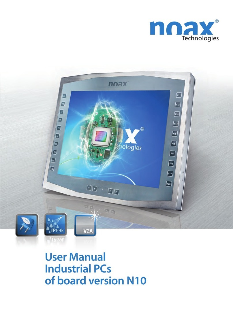
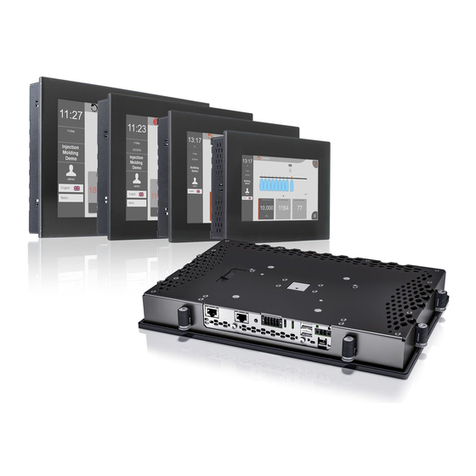
noax C12 User manual


Operating instructions Industrial PC
BDA−N6−ALL−US−1.0www.noax.comPage 2 of 28
We reserve the right to make technical changes.
All rights reserved. No part of this document may be reproduced, transferred, copied, stored on a retrieving system or transla-
ted into another language, by any means whatsoever, with the exception of personal use, without the written permission
of noax Technologies AG. All product names are registered trademarks or subject to the copyright of their respective compa-
nies.

Table of Contents
BDA−N6−ALL−US−1.0 www.noax.com Page 3 of 28
Table of Contents
1 Safety 5. . . . . . . . . . . . . . . . . . . . . . . . . . . . . . . . . . . . . . . . . . . . . . . . . . . . . . . . . . . . . . . . . . . . . .
1.1 Pictograms and symbols 5. . . . . . . . . . . . . . . . . . . . . . . . . . . . . . . . . . . . . . . . . . . .
1.2 Intended Use 5. . . . . . . . . . . . . . . . . . . . . . . . . . . . . . . . . . . . . . . . . . . . . . . . . . . . . .
1.3 Safety instructions 6. . . . . . . . . . . . . . . . . . . . . . . . . . . . . . . . . . . . . . . . . . . . . . . . .
1.3.1 Upgrades and maintenance work to the Industrial PC 7. . . . . . . . . . . . . . . . . .
1.3.2 Touch display 7. . . . . . . . . . . . . . . . . . . . . . . . . . . . . . . . . . . . . . . . . . . . . . . . . . . . .
2 Power units 8. . . . . . . . . . . . . . . . . . . . . . . . . . . . . . . . . . . . . . . . . . . . . . . . . . . . . . . . . . . . . . . . .
2.1 External table power unit 8. . . . . . . . . . . . . . . . . . . . . . . . . . . . . . . . . . . . . . . . . . . .
2.2 External power unit IP65 9. . . . . . . . . . . . . . . . . . . . . . . . . . . . . . . . . . . . . . . . . . . .
3 Installation and setup 10. . . . . . . . . . . . . . . . . . . . . . . . . . . . . . . . . . . . . . . . . . . . . . . . . . . . . . . .
3.1 Installation site 10. . . . . . . . . . . . . . . . . . . . . . . . . . . . . . . . . . . . . . . . . . . . . . . . . . . . .
3.2 Mounting C12 and C15 compact enclosures 11. . . . . . . . . . . . . . . . . . . . . . . . . .
3.3 Mounting the stainless steel S12 and S15 13. . . . . . . . . . . . . . . . . . . . . . . . . . . . .
3.4 Installation of the Panel Mount P12 and P15 14. . . . . . . . . . . . . . . . . . . . . . . . . . .
4 Operation 16. . . . . . . . . . . . . . . . . . . . . . . . . . . . . . . . . . . . . . . . . . . . . . . . . . . . . . . . . . . . . . . . . . .
4.1 Operating and display elements 16. . . . . . . . . . . . . . . . . . . . . . . . . . . . . . . . . . . . .
4.1.1 General instructions concerning the keys 16. . . . . . . . . . . . . . . . . . . . . . . . . . . . .
4.1.2 Display area 17. . . . . . . . . . . . . . . . . . . . . . . . . . . . . . . . . . . . . . . . . . . . . . . . . . . . . . .
4.1.3 Key area 17. . . . . . . . . . . . . . . . . . . . . . . . . . . . . . . . . . . . . . . . . . . . . . . . . . . . . . . . . .
4.2 Operation 17. . . . . . . . . . . . . . . . . . . . . . . . . . . . . . . . . . . . . . . . . . . . . . . . . . . . . . . . .
4.2.1 CFL background illumination 17. . . . . . . . . . . . . . . . . . . . . . . . . . . . . . . . . . . . . . . .
4.3 Connections in the jack area 18. . . . . . . . . . . . . . . . . . . . . . . . . . . . . . . . . . . . . . . .
5 Servicing and cleaning of the Industrial PC 19. . . . . . . . . . . . . . . . . . . . . . . . . . . . . . . . . . .
6 Troubleshooting 20. . . . . . . . . . . . . . . . . . . . . . . . . . . . . . . . . . . . . . . . . . . . . . . . . . . . . . . . . . . . .
6.1 N6 error codes 20. . . . . . . . . . . . . . . . . . . . . . . . . . . . . . . . . . . . . . . . . . . . . . . . . . . .
6.2 Handling repairs 20. . . . . . . . . . . . . . . . . . . . . . . . . . . . . . . . . . . . . . . . . . . . . . . . . . .
6.3 FAQ − frequently asked questions 21. . . . . . . . . . . . . . . . . . . . . . . . . . . . . . . . . . .
7 Technical data 22. . . . . . . . . . . . . . . . . . . . . . . . . . . . . . . . . . . . . . . . . . . . . . . . . . . . . . . . . . . . . .
7.1 Weights 22. . . . . . . . . . . . . . . . . . . . . . . . . . . . . . . . . . . . . . . . . . . . . . . . . . . . . . . . . . .
7.2 Materials 22. . . . . . . . . . . . . . . . . . . . . . . . . . . . . . . . . . . . . . . . . . . . . . . . . . . . . . . . . .
7.3 Ambient conditions 22. . . . . . . . . . . . . . . . . . . . . . . . . . . . . . . . . . . . . . . . . . . . . . . . .
7.4 External power units 22. . . . . . . . . . . . . . . . . . . . . . . . . . . . . . . . . . . . . . . . . . . . . . . .
7.5 Mainboard 23. . . . . . . . . . . . . . . . . . . . . . . . . . . . . . . . . . . . . . . . . . . . . . . . . . . . . . . .
7.6 Technical data IPC 23. . . . . . . . . . . . . . . . . . . . . . . . . . . . . . . . . . . . . . . . . . . . . . . . .
7.7 Additional cards in the ISA/PCI slot 23. . . . . . . . . . . . . . . . . . . . . . . . . . . . . . . . . . .
7.8 Fuses 24. . . . . . . . . . . . . . . . . . . . . . . . . . . . . . . . . . . . . . . . . . . . . . . . . . . . . . . . . . . .
8 Declaration of conformity 25. . . . . . . . . . . . . . . . . . . . . . . . . . . . . . . . . . . . . . . . . . . . . . . . . . . .
9 Your notes 26. . . . . . . . . . . . . . . . . . . . . . . . . . . . . . . . . . . . . . . . . . . . . . . . . . . . . . . . . . . . . . . . . .

Operating instructions Industrial PC
BDA−N6−ALL−US−1.0www.noax.comPage 4 of 28
This manual describes all variants of the Industrial PC with the mainboard N6A / −B und −C.
íOld device designations are in parentheses.
Enclosure types
Mainboard variants
íPlease find more information on our web page at www.noax.com.
Compact enclosure 12 inch C12 (K12)
Compact enclosure 15 inch C15
Stainless steel enclosure 12 inch S12
Stainless steel enclosure 15 inch S15
(E15)
Panel mount enclosure 12 und 15 inch
P12, P15 (FE12, FE15)
The specifications of your N6 (P6) mainboard
are listed on the type plate (A, B or C: For
differences see the technical data in chapter
7)

Safety
BDA−N6−ALL−US−1.0 www.noax.com Page 5 of 28
1 Safety
To avoid injuries or damage, it is imperative that you read and follow the user and safety in-
structions.
The manufacturer/supplier will not be liable for any damage caused by not observing these
instructions.
1.1 Pictograms and symbols
The following pictograms and symbols are used in this operating manual.
Potential life−threatening danger sources are indicated by a warning sign with an exclama-
tion point. This sign also applies to any possible damage to the device.
Potential life−threatening danger sources from electricity are indicated by a warning sign
with a lightning symbol. This sign also applies to any possible damage to the device.
Potential life−threatening danger sources from heat are indicated by a warning sign with a
heat symbol.
Potential life−threatening danger sources from explosion are indicated by a warning sign
with an explosion symbol. This sign also applies to any possible damage to the device.
íMandatory instructions are indicated by í.
íParticularly important instructions are also in bold.
FNumerical lists and conditions are indicated by a black dot.
"Operating instructions which have to be performed by the operator are indicated with a black arrow.
1.2 Intended Use
Your Industrial PC has been built to the latest technology and safety regulations.
íPlease use the Industrial PC only when it is in a good, undamaged condition! Any problems
and/or malfunctions which could reduce safety must be corrected immediately (for example,
defective power cord or enclosure)! Our professional service will take care of any repair.

Safety
BDA−N6−ALL−US−1.0www.noax.comPage 6 of 28
1.3 Safety instructions
It is imperative that you read this manual before operating the Industrial PC.
This manual belongs with the Industrial PC and must remain with it.
Follow accident prevention and safety rules!
Do not allow liquids or harmful vapors (e.g. from cleaning agents) to get into the non−NEMA
protected electronics area.
Only allow authorized professionals to repair the ProTouch. Unprofessional work on electric
and electronic devices may cause electrical shocks.
These PC’s contain electronic devices with highly integrated components. These electronic
components highly sensitive to surges and therefore also to the discharge of static electricity.
To avoid damage, static electricity must be removed from the body before touching electronic
components. For this purpose, touch a metal part on the ProTouch which is not insulated such
as the connector panel or the metal enclosure.
Do not open the power supply at any time! There are no maintainable components inside.
Mount the power supply only with the mounting bracket provided or the mounting holes (on
no account on the cord). Do not cover the power supply or mount it in a too small enclosure,
otherwise there is danger of overheating. For safety reasons, the power unit must be mounted
in a way that it can be disconnected from the outlet at all times.
The power unit may only be connected to an outlet with a ground wire. Use the power cord
provided, as it complies with all latest safety regulations.
Operate the Industrial PC only with the power supply provided or use an optional connection
cord with an integrated fuse (can be provided as an option).
Ensure that the electrical specifications on the attached label correspond to the power supply
or outlet!
External devices (e.g. maintenance floppies, scanners...) may only be connected or discon-
nected to/from the Industrial PC is shut off, otherwise the Industrial PC electronics or the ex-
ternal device could become damaged! Wait at least five seconds after shutting off the Indu-
strial PC before connecting an external device (with the exception of connecting Hot Plug de-
vices to USB and Firewire interfaces).
Please take care, that the connecting cables to the Industrial PC, are not too short or stretched.
Power units
External
devices

Safety
BDA−N6−ALL−US−1.0 www.noax.com Page 7 of 28
1.3.1 Upgrades and maintenance work to the Industrial PC
Before opening the device to upgrade or service it, the Industrial PC must be completely di-
sconnected from the power supply! For this purpose, unplug the cord for the power supply
from the "Power" connector of the Industrial PC. Simply turning off is not sufficient!
The Industrial PC may only be opened by authorized professionals with fundamental PC
knowledge and not by a layperson. Should upgrades or maintenance work be improperly car-
ried out, the warranty is no longer valid. Our service is recommended.
Faulty and damaged electrical equipment and parts must always be replaced by expert electri-
cians only!
Please note after opening the Industrial PC that some components can become very hot du-
ring operation (e.g. memory or hard drive). Allow these components to cool off before tou-
ching them.
Please use only batteries of the same type or those of a similar type recommended by the ma-
nufacturer. Please dispose of the batteries according to the manufacturer’s directions.
There is danger of explosion if the CMOS battery is not properly inserted. Insert the battery
with the "+" side facing upwards (the "+" sign must be legible after having been inserted).
1.3.2 Touch display
To avoid damage and malfunction, do not use pointed, sharp or harsh objects to touch the
screen! Optional protective film is available.
Do not beat or use extreme pressure to touch the display, as this could damage or destroy
it (resulting in broken glass, for example).
Do not place the Industrial PC face down on a hard surface. If necessary, place a soft cloth
or a piece of foam underneath the unit and make sure that no objects (e.g. screws) can damage
the display.
Only use soft cloths to clean the touch screen. Avoid scratches.
Please also observe the instructions in the chapter 5 "Servicing and cleaning the Industrial
PC".
Batteries

Power supplies
BDA−N6−ALL−US−1.0www.noax.comPage 8 of 28
2 Power supplies
2.1 External power supply
Fig. 15 External power supply unit
Fig. 16 Mounting bracket
The external table power unit consists of the
following components:
FPower cord
FPower unit with connecting cord to the
device
FInstallation frame for attaching the device
The mounting bracket serves the purpose of
holding the external power supply unit. The
external power supply unit can be mounted
directly on the wall, for example, using the
mounting holes in the bracket.

Power supplies
BDA−N6−ALL−US−1.0 www.noax.com Page 9 of 28
2.2 External power supply NEMA4 (IP65)
Fig. 17 External power supply NEMA4
Fig. 18 Mounting holes
198
174
145
130
14.5
4.5
atleast220
144
The external power supply with a degree of
protection NEMA4 can be mounted directly
on the wall, for example, using the mounting
holes.
To mount the external power pack, transfer
the distances between the drill holes shown in
the drawing to the surface provided for at-
tachment.

Installation and setup
BDA−N6−ALL−US−1.0www.noax.comPage 10 of 28
3 Installation and setup
3.1 Installation site
The Industrial PC is designed for challenging (harsh) environments.
However, please following the installation regulations:
FAvoid exposing the display to sun.
FDo not install the Industrial PC to be directly influenced by heat sources. Please see that there
is sufficient circulation of the rear panel, or rather, of the cool fins at the rear panel.
FLeave a minimum of 0.6 inch (15 mm) space to ensure sufficient air circulation.
íThe device will switch off on its own if the temperature is out of the operating range.
FDo not mount the Industrial PC on heavily vibrating surfaces. If this cannot be avoided, attach
the device to shock and vibration absorbers.
FWhen the ProTouch is used on fork lifts or similar vehicles, it is imperative that you take addi-
tional measures to absorb shocks and reduce vibrations (available as an option: "Modifica-
tion for mobile use").
Special mounting brackets are available for mobile applications.
íYou can find more information about installation and mounting brackets on our web
page www.noax.com.

Installation and setup
BDA−N6−ALL−US−1.0 www.noax.com Page 11 of 28
3.2 Mounting C12 and C15 compakt enclosures
Fig. 19 T−bar and screws
Two stoppers are factory installed at the top of both T−bar slots. The stoppers prevent the Industrial
PC T−bars from sliding through the t−bar slots and align the Industrial PC. This makes the attach-
ment easier.
TA variety of mounting brackets is available for the Industrial PC .
"Screw the T−bars (DIN 508 / M5x6) directly onto the wall (e.g. door of the control cabinet) and
slide the Industrial PC into them.
"Use the T−bars to attach the optional mounting brackets
Caution danger of injury:
For safety reasons, do not remove the firmly placed stoppers from the T−Slots. Make sure
that the T−bars and stoppers are securely tightened!
íPlease find more information about the mounting brackets in our web page www.noax.com.
Factory−
made
groove sto-
nes
Device hol-
ders (optio-
nal)
The Industrial PC Compact is attached using
the rear panel of the cooling element, which
has two guide bars with a T−slot for groove
stones.
The groove stones (DIN 508/ M5x6) and
screws (M5x10) with washers are included in
delivery.

Operation
BDA−N6−ALL−US−1.0www.noax.comPage 16 of 28
4 Operation
4.1 Operating and indicator devices
All operating and inidactor devices are located on the front of the Industrial PC. There are LED’s in
the upper area and keys in the lower area.
Fig. 27 Operating and indicator devices
1
2
Compact enclosure 12 Zoll C12
Stainless steel enclosure 12 Zoll S12
Front installation enclosure 12 Zoll P12
Compact enclosure 15 Zoll C15
1 − Display area
2 − Key area
íThe stainless steel Industrial PC. S15 and the Panel Mount ProTouch P15 do not have any operating
or indicator devices.
4.1.1 General key function information
The light−emitting diode INPUT will light up, or rather, flash as soon as a key has been pressed.
Press the keys as close to the middle of the symbol as possible.

Operation
BDA−N6−ALL−US−1.0 www.noax.com Page 17 of 28
4.1.2 Display area
The functions of the operating and display elements can be modified in the software’s setup. The
following overview describes the functions in the factory settings.
Light−emitting diode Function
POWER Lights up as soon as the Industrial PC is turned on.
INPUT Lights up at valid entry
HDD Lights up when the hard drive is accessed.
OK Lights up after the Industrial PC has successfully completed the
internal function test and all functions are in order.
ERROR Lights up when a problem or an error occurrs at the Industrial
PC.
íSee troubleshooting chapter 6
4.1.3 Key area
Key Function
BRIGHTNESS + Increase brightness
−Decrease brightness
CONTRAST + Not used!
−Not used!
ON−OFF I Turn on the Industrial PC or. CFL back light, trigger the hard reset
OShut off the Industrial PC or CFL back light.
4.2 Operation
íThe functions of the operating and display elements can be restricted or deactivated in the softwa-
re’s setup. The following overview describes the functions in the standard settings. This software
can be downloaded on the Internet.
Function Standard settings
Turn on the Industrial PC "Press the ON (I) for at least one second
Turn off the Industrial PC "Press OFF (O) for at least 5 seconds
Set the display’s brightness "To change the brightness by one level, tap the [+] or [−]
key briefly
"To continuously change the brightness, keep the [+] or [−]
key pressed down
Trigger the hard reset "Press the ON (I) key for more than 5 seconds
4.2.1 CFL back light
The integrated CFL back light will dim to an adjustable, reduced brightness 3 minutes after the last
time a key has been pressed or the display has been touched.
Function Standard settings
Dim "3 minutes after a key has been pressed or the screen has
been touched
Reactivate "Press any key on the external PS2 keyboard (only PS2, not
USB)
"Press the ON key
"Press the touch surface
"Moving a PS/2 mouse
íYou can reactivate the back light by briefly pressing the key ON (I).

Operation
BDA−N6−ALL−US−1.0www.noax.comPage 18 of 28
4.3 Connector area
Fig. 28 Drawing of the connector pane
11
1 − Opening for an ISA / PCI combi slot
Optional labeling of the serial interface COM1 / COM2 :
RS232P5 RS232 interface with 5 V voltage output
(5 to Pin 4)
RS232P12 RS232 interface with 12 V voltage output
(12 to Pin 4)
RS422DP RS422DP interface with 5 V and 12 V voltage output
(Dual power 12 V to Pin 4 and 5 V to Pin 9)
RS485DP RS485DP interface with 5 V and 12 V voltage output
(Dual power 12 V to Pin 4 and 5 V to Pin 9)
TTY20mA TTY 20 mA interface
(Current loop)
Plug or unplug the devices only when the power is off.
Exception: USB and IEEE 1394 (Firewire)
íPlease find more information about optional serial interface modules on our web page
www.noax.com.

Servicing and cleaning of the Industrial PC
BDA−N6−ALL−US−1.0 www.noax.com Page 19 of 28
5 Servicing and cleaning of the Industrial PC
"Turn off the device and disconnect it from the power supply.
"Use typical commercial plastic cleaners and a soft, lint−free cloth
"Do not put the cleaning agent directly on the Industrial PC, rather first on the cloth
"If at all possible, clean when damp (not wet, with the exception of IP65 devices) and do not
press the cleaning agent under the touch seals
"Clean the surface and the display window without applying pressure
"Remove the cleaning agent completely from the device using a clean cloth
For further protection from mechanical wear, we offer a special protective film that can be
changed after being used.
Do not on any account clean the display window with cleaning agents which contain abrasi-
ves. The surface will become scratched and matt.
You can find more information on the Internet at www.noax.com.

Troubleshooting and repair
BDA−N6−ALL−US−1.0www.noax.comPage 20 of 28
6 Troubleshooting and repair
In this chapter you will find necessary information in case of problems with the Industrial PC.
íIn case one of the following problems occurs, the device will shut off automatically
FInput voltage too high / too low
FInternal voltage too high / too low
FSystem temperature too high / too low
FFan speed too high / too low
6.1 N6 error codes
If an error occurs , the integrated MCU will display an error code on the display section LED’s, which
shows more specific information about the type of error. As soon as the Error" LED permanently
lights up, the LED’s OK", INPUT" and POWER" no longer have their normal functions but display
an error code. Please make a note of this error code and notify the hotline:
Tel.: +49(0)80 92−8536−33
Fax +49(0)80 92−8536−55
eMail: [email protected]
íYou can find more information about this error code on the noax web page in the service section
under FAQ..
6.2 Handling repairs
Please follow these guidelines for fast and smooth repair handling.
FPlease use our service cover letter, which is available on the web page at www.noax.com as
a PDF or Word file. Fill out the form as completely as possible and enclose it with the device
being returned.
FPlease make a backup of your data before sending your ProTouch. We assume no liability for
accidental loss of your data.
FShould your system be password protected, please either delete the password or let us know
what it is. Otherwise we will have to reset the password.
FPlease see that the Industrial PC. is securely packages (preferably in the original noax carton).
We assume no liability for damage incurred during transportation.
FWe recommend sending the package by UPS Standard. In case of warranty, we will not pay
for additional services such as express services, etc. Please affix the appropriate paperwork.
During warranty we will pay the UPS Standard charges.
This manual suits for next models
5
Table of contents
Other noax Industrial PC manuals


