noax N11 User manual

User Manual
Industrial PCs
of board version N11
3085-US

User Manual N11 Industrial PC
www.noax.comPage 2 of 120 3085-US-2.4
Subject to change without notice!
Copyright © 2019 –All rights reserved.
No part of this document may be duplicated, transmitted, copied, saved on a retrievable system, or translated into another
language, regardless of the manner or the means in which this is done, without the written consent of noax Technologies
AG, except for personal use.
All product names are registered trademarks or are subject to the copyright of their relevant companies.

User Manual N11Industrial PC
3085-US-2.4 www.noax.com Page 3 of 120
Table of Contents
1 About this manual 8...........................................................
1.1 Target group 8......................................................
1.2 Requirements 8.....................................................
1.3 Signal words 8......................................................
1.4 Symbols 9..........................................................
1.4.1 Indicative symbols 9.................................................
1.4.2 List symbols 9.......................................................
1.5 Distinctions 10.......................................................
1.6 Abbreviations and technical terms 10....................................
2 Intended use 11................................................................
3Scope of delivery 11...........................................................
4General safety instructions 12..................................................
4.1 Documentation 12....................................................
4.2 Handling the device 12................................................
4.3 Devices with internal power supply 13...................................
4.4 External power supply 13..............................................
4.5 External devices 13...................................................
4.6 Cleaning information 13...............................................
4.7 Safety information for selected countries 14..............................
4.7.1 Denmark 14..........................................................
4.7.2 Finland 14...........................................................
4.7.3 Norway 14...........................................................
4.7.4 Sweden 14...........................................................
5 Device types 15................................................................
5.1 Information on the noax rating plate 20..................................
5.1.1 Rating plate for IPC type S12, S15, S15‐G2, S19, P15 20..................
5.1.2 Rating plate for IPC type C12, C12P, C15, C15P, C19, C21W 21.............
5.1.3 Rating plate for IPC type S15P, S15R, S19P, S19R, S21WP, S21WR 22.......
6 Power supplies 23.............................................................
6.1 External power supply 23..............................................
6.2 External power supply IP65 (NEMA 4) 24................................
7 Safety instructions for initial operation 25........................................
7.1 Touchscreen 27......................................................
7.2 Measures for compliance with EMC guidelines 27.........................
8 Installation 28..................................................................
8.1 Installation location 28.................................................
8.2 Tightening torques for screws 29.......................................
8.3 Tools 29.............................................................
8.4 Connector protection 29...............................................

User Manual N11 Industrial PC
www.noax.comPage 4 of 120 3085-US-2.4
8.5 Industrial PC Compact - C12 and C12P 30. .............................
8.5.1 Industrial PC Compact - C12 30.......................................
8.5.2 Industrial PC Compact - C12P 31......................................
8.5.3 T‐slot nuts 32.........................................................
8.5.4 Stoppers in the T‐slots at the rear side of enclosure 32.....................
8.5.5 VESA 100 mounting option 32..........................................
8.5.6 VESA 75 mounting option 32...........................................
8.6 Industrial PC Compact - C15, C15P, C19, C21W 33.......................
8.6.1 Industrial PC Compact - C15 33.......................................
8.6.2 Industrial PC Compact - C15P 34......................................
8.6.3 Industrial PC Compact - C19 35.......................................
8.6.4 Industrial PC Compact - C21W 36.....................................
8.6.5 T‐slot nuts 37.........................................................
8.6.6 Stoppers in the T‐slots at the rear side of enclosure 37.....................
8.6.7 VESA 200 x 100 mounting option 37....................................
8.6.8 VESA 100 mounting option 37..........................................
8.7 Industrial PC Steel - S12 and S15 38...................................
8.8 Industrial PC Steel - S15‐G2 and S19 39................................
8.8.1 Industrial PC Steel - S15‐G2 39........................................
8.8.2 Industrial PC Steel - S19 40...........................................
8.8.3 VESA 100 mounting option 41..........................................
8.8.4 Side mounting options 41..............................................
8.9 Industrial PC Panel - P15 42...........................................
8.9.1 Installation cut‐out for the Industrial PC Panel - P15 42....................
8.10 Industrial PC Steel - S15P, S15R, S19P, S19R, S21WP and S21WR 43......
8.10.1 Industrial PC Steel - S15P and S15R 43................................
8.10.2 Industrial PC Steel - S19P and S19R 44................................
8.10.3 Industrial PC Steel - S21WP and S21WR 45.............................
8.10.4 VESA 100 mounting option 45..........................................
9 Connectors and interfaces 46...................................................
9.1 Connector for equipotential bonding 46.................................
9.2 Connector area in general 47...........................................
9.3 Connector area C12 and C12P 47......................................
9.4 Connector area C15, C15P, C19, C21W, S15P, S15R, S19P, S19R,
S21WP, S21WR with option “internal power supply” 48....................
9.5 Connector area S15 with option “internal power supply” 49................
9.6 Connector area of S15‐G2 and S19 50..................................
9.7 Standby supply for the USB ports 51....................................
9.8 SIM card 51..........................................................
9.9 LAN port 51..........................................................
9.10 Front USB port / Side USB port 52......................................
9.10.1 Front USB port 52....................................................
9.10.2 Side USB port 52.....................................................
9.11 SATA mode AHCI/RAID 53.............................................
9.12 PCIe (PCI Express) description 54......................................
9.13 Information about power supply over noax interface modules 55............

User Manual N11Industrial PC
3085-US-2.4 www.noax.com Page 5 of 120
9.14 RS232 interface module 56............................................
9.14.1 Connector pinout 56..................................................
9.14.2 Power supply for RS232 devices 57.....................................
10 Operation 58...................................................................
10.1 Touchscreen technologies 58..........................................
10.1.1 Resistive touchscreen 58..............................................
10.1.2 Projected capacitive touchscreen 58....................................
10.2 Operation and display elements for device types C12, C15, C19, C21W 59. . .
10.2.1 General key information 59............................................
10.2.2 Ambient light sensor (ALS) 59..........................................
10.2.3 LED area 60..........................................................
10.2.4 Key area 60..........................................................
10.2.5 Function keys F1 to F3 60.............................................
10.3 Operation and display elements for device type C12P, C15P 61.............
10.3.1 General key information 61............................................
10.3.2 Ambient light sensor (ALS) 62..........................................
10.3.3 LED area 62..........................................................
10.3.4 Key area 62..........................................................
10.3.5 Function keys F1 to F3 62.............................................
10.4 Operation and display elements for device type S12 63....................
10.4.1 General key information 63............................................
10.4.2 Control panel 63......................................................
10.5 Operation and display elements for device types S15‐G2, S19 64...........
10.5.1 General key information 64............................................
10.5.2 Ambient light sensor (ALS) 65..........................................
10.5.3 LED area 65..........................................................
10.5.4 Key area 65..........................................................
10.5.5 Function keys F, F1 to F20 65..........................................
10.6 Operation and display elements for device type
S15P, S15R, S19P, S19R, S21WP, S21WR 66.............................
10.6.1 General key information 66............................................
10.6.2 Ambient light sensor (ALS) 67..........................................
10.6.3 LED area 67..........................................................
10.6.4 Key area 67..........................................................
10.6.5 Function keys F1 to F3 67.............................................
10.7 Factory default settings for operation elements 68........................
10.7.1 Device types C12, C15, C19, C21W, S15‐G2, S19 68......................
10.7.2 Device type S12 69...................................................
10.7.3 Device types S15, P15 69..............................................
10.7.4 Device type C12P, C15P, S15P, S19P, S21WP 70..........................
10.7.5 Device type S15R, S19R, S21WR 71....................................
10.8 Automatically reducing the screen brightness 72..........................
10.9 “Touch Power On” function 72..........................................
10.10 Calibrating the touchscreen 72.........................................

User Manual N11 Industrial PC
www.noax.comPage 6 of 120 3085-US-2.4
11 Software nSMART™ 73.........................................................
11.1 noax Microcontroller (MCU) 73.........................................
11.2 Launching the software nSMART™ 73...................................
11.3 Settings with software nSMART™ 74....................................
11.4 Device information 74.................................................
11.5 Assigning / configuring the function keys 75..............................
11.5.1 Program start via function key 77.......................................
11.6 Calibrating touch points for “Touch Power On” 77.........................
11.7 Function “Touch calibration” 79.........................................
11.7.1 Calibrating the touchscreen 79.........................................
11.8 Launching touchscreen cleaning mode 81...............................
12 Upgrades and maintenance work 82.............................................
12.1 Opening and closing the Industrial PC 82................................
12.1.1 Steps to open the Industrial PC 82......................................
12.1.2 Steps to close the Industrial PC 83......................................
12.2 Handling components 83..............................................
12.3 Replacing the CMOS battery 84........................................
13 Cleaning the Industrial PC 85...................................................
13.1 General cleaning information 85........................................
13.1.1 Devices with PCAP touchscreen 86.....................................
13.2 Touchscreen cleaning mode 86.........................................
13.2.1 Starting cleaning mode with nSMART™ 86...............................
13.2.2 Starting cleaning mode with a key combination 86........................
14 Troubleshooting 87.............................................................
14.1 Behavior at temperature limits 87.......................................
14.2 Frequently asked questions (FAQs) 87..................................
14.3 Error codes – LED displays for errors 88.................................
14.4 Repairs 89...........................................................
14.5 Download Center 89..................................................
15 Technical data 90..............................................................
15.1 General information for the Industrial PC 90..............................
15.1.1 Environmental conditions 90...........................................
15.1.2 Operating position of the Industrial PC 90................................
15.1.3 Resistive touchscreen 91..............................................
15.1.4 Projected capacitive touchscreen 91....................................
15.2 Technical data on the Industrial PC variants 92...........................
15.2.1 Device type Compact - C12 and C12P 92...............................
15.2.2 Device type Compact - C15 and C15P 93...............................
15.2.3 Device type Compact - C19 94........................................
15.2.4 Device type Compact - C21W 95......................................
15.2.5 Device type Steel - S12 96............................................
15.2.6 Device type Steel - S15 97............................................
15.2.7 Device type Steel - S15‐G2 98.........................................
15.2.8 Device type Steel - S19 99............................................

User Manual N11Industrial PC
3085-US-2.4 www.noax.com Page 7 of 120
15.2.9 Device type Panel - P15 100............................................
15.2.10 Device type Steel - S15P 101...........................................
15.2.11 Device type Steel - S15R 102...........................................
15.2.12 Device type Steel - S19P 103...........................................
15.2.13 Device type Steel - S19R 104...........................................
15.2.14 Device type Steel - S21WP 105.........................................
15.2.15 Device type Steel - S21WR 106.........................................
15.3 Technical data on the mainboards 107....................................
15.3.1 Mainboard N11G 107..................................................
15.3.2 Mainboard N11F 108...................................................
15.3.3 Mainboard N11C 109...................................................
15.3.4 CMOS battery 109.....................................................
15.4 Technical data on the external power supplies 110.........................
15.4.1 External power supply 110..............................................
15.4.2 External power supply IP65 (NEMA 4) (24 V) 110..........................
15.5 Interface module 111...................................................
15.5.1 noax RS232 interface module 111.......................................
15.6 Fuses 111............................................................
15.6.1 Devices without internal power supply 112................................
15.6.2 Device type S15‐G2 and S19 as well as C15, C15P, C19, C21W, S15P, S15R,
S19P, S19R, S21WP, S21WR with option “Internal power supply” 112.........
15.6.3 Device type S15 with option “Internal power supply” 112...................
15.7 Requirements for additional components 113.............................
15.8 Expansion cards for the Industrial PC 113.................................
15.8.1 Expansion cards in the PCI slot 113......................................
15.8.2 Expansion cards in the PCI Express slot 114..............................
15.8.3 Expansion cards in the PCI Express Mini Card slot 114.....................
16 Disposal 115....................................................................
17 Declarations of conformity 116...................................................
17.1 CE conformity 116.....................................................
17.2 FCC conformity 116....................................................
17.3 WEEE 116............................................................
17.4 Declarations of conformity as downloads 116.............................
18 Your notes 117..................................................................

User Manual N11 Industrial PC
www.noax.comPage 8 of 120 3085-US-2.4
1About this manual
1.1 Target group
This manual is intended for qualified specialist personnel.
It serves to complete their knowledge about proper installation, commissioning, and
maintenance of the device.
However, the manual does not replace expert knowledge.
1.2 Requirements
In order to be able to understand and properly implement the descriptions in this
document, basic skills in installation, software installation and maintenance of technical
devices are required.
1.3 Signal words
The following signal words are used in this document:
Danger
Danger indicates warnings which could lead to death or serious injury if
ignored.
Warning
Warning indicates warnings which could lead to minor injury or severe
material damage if ignored.
Caution
Caution indicates warnings which could lead to minor material damage
if ignored.

User Manual N11Industrial PC
3085-US-2.4 www.noax.com Page 9 of 120
1.4 Symbols
The following symbols are used in this document:
1.4.1 Indicative symbols
This manual contains instructions which must be observed to ensure your personal
safety and to prevent damage to property.
Warning regarding dangers in association with one of the signal words Caution,
Warning, or Danger.
Warning regarding dangers involving electricity in association with one of the signal
words Caution, Warning, or Danger.
Warning regarding dangers involving electrostatic discharge in association with one of
the signal words Caution, Warning, or Danger.
Warning regarding dangers involving burns on hot surfaces in association with one of
the signal words Caution, Warning, or Danger.
Warning regarding dangers involving explosions in association with one of the signal
words Caution,Warning, or Danger.
Warning regarding corrosives in association with one of the signal words Caution,
Warning, or Danger.
Note on using the product.
Failure to observe these instructions may result in an adverse event or an
undesirable condition.
Cross reference to other chapters.
1.4.2 List symbols
DList
-Subitem in a list
"Instruction which consists of only 1 step.
1. Instruction which consists of several steps.
The steps must be performed in the specified order.
User Manual N11 Industrial PC
www.noax.comPage 10 of 120 3085-US-2.4
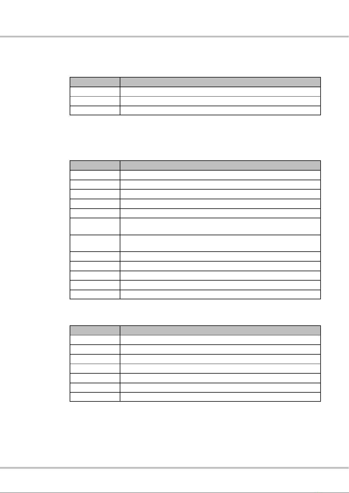
1.5 Distinctions
The following distinctions are used in this document:
Distinction
Description
Italics
Emphasis
Bold
Product name or strong emphasis
Courier
Term from software interfaces (GUI) and device labels
1.6 Abbreviations and technical terms
The following abbreviations are used in this document:
Abbreviation
Description
ALS
Ambient Light Sensor
CFL
Compact Fluorescent Lamp
CPU
Central Processing Unit
GPRS
General Packet Radio Service
HDD
Hard Disk Drive
IMEI
International Mobile Equipment Identity
(unique serial number for GSM and UMTS devices)
MAC
Media Access Control
(network adapter hardware address)
SIM
Subscriber Identity Module
UMTS
Universal Mobile Telecommunications System
Windows
Microsoft Windows operating system
WLAN
Wireless Local Area Network
PCAP
Projected capacitive touchscreen
The following technical terms are used in this document:
Abbreviation
Description
AHCI
Advanced Host Controller Interface
RAID
Redundant Array of Independent Disks
GUI
Graphical User Interface
MCU
Microcontroller Unit
NCQ
Native Command Queuing
PCI
Peripheral Component Interface
PCIe
Peripheral Component Interface express

User Manual N11
Intended use
Industrial PC
3085-US-2.4 www.noax.com Page 11 of 120
2 Intended use
Your Industrial PC has been manufactured according to current technical standards
and complies with approved safety regulations.
noax Industrial PCs are designed to be used for the collection of operating and ma
chine data, visualization, logistics, or controlling machines and equipment.
noax Industrial PCs are used in the harshest of industrial environments, such as within
the production, logistics, food processing and chemical industries. Depending on the
housing variant (see Chapter 5), they can be installed such that they are stationary or
mobile on vehicles.
Any other use is not in compliance with the intended use.
The user or operator of the noax device is solely liable for any resulting damage.
This also applies to unauthorized modifications to the device.
Use the industrial PC only if it is in perfect condition and not damaged in any way.
3 Scope of delivery
Check the contents of the packaging to make sure that everything listed on the delivery
slip is there. When checking, empty everything out of the packaging.
If the goods that have been delivered to you do not correspond to your delivery slip,
please contact the noax hotline.
(
Please find contact information on the back cover of this user manual.
The packaging has been designed specifically for the noax Industrial PC to prevent
damage during transportation. Please keep this packaging safe.
Always use this packaging when transporting the Industrial PC.

User Manual N11
General safety instructions
Industrial PC
www.noax.comPage 12 of 120 3085-US-2.4
4General safety instructions
When using products which come into contact with electrical voltages, the valid VDE/
IEC/EN regulations must be observed.
Warning
Repairs on the Industrial PC should only be carried out by authorized specialist person
nel.
Warning
Never repair the device yourself. Always contact the noax hotline instead and send in
your device to be repaired if necessary.
The device information required when you contact the hotline can be found on the
Industrial PC rating plate. Important information about the features of your device is
documented here. Please always give the technician the full type code and serial
number (for rating plate see Chapter 5.1.1 or 5.1.2 / for device information from nS
MART™ see Chapter 11.4).
4.1 Documentation
DTo avoid injury and damage, it is important to read and observe the following usage
and safety information before initial operation.
DThe manufacturer/supplier accepts no liability for any damage that occurs as a
result of failing to comply with these instructions.
DKeep this documentation and make sure to include it when passing on the device.
4.2 Handling the device
DRespect the weight of the devices when handling them (e.g., transportation,
installation).
DOnly use the device if it is in perfect condition. Replace defective devices immedi
ately, especially when:
-The power cable or power socket is damaged.
-Liquid has entered the device.
-The device no longer works as described in the documentation.
-The housing is damaged.
DCheck that the values specified on the rating plate correspond to the electrical
ratings for your power supply.
DIP protection class:
Make sure that liquids and aggressive vapors (e.g., from cleaning agents) are not
able to enter areas without an IP protection class, such as the connector area.
DBatteries:
Only use batteries of the same type or those of equivalent types recommended by
the manufacturer.
Follow the instructions provided in Chapter 16 on “Disposal”.

User Manual N11
General safety instructions
Industrial PC
3085-US-2.4 www.noax.com Page 13 of 120
4.3 Devices with internal power supply
Applies to device types S15‐G2 and S19 as well as devices with the option
“Internal power supply”
DUse only the mains cable that was supplied with devices with internal power supply
because only this cable used in conjunction with the safety catch can ensure se
cure locking of the plug connection.
DThe device should only be operated using a circuit secured in line with standards
with a protective earth conductor and a plug connection with a protective earth
contact.
DEnsure that the mains cable is not damaged.
4.4 External power supply
DThe external power supply should not be opened for any reason.
It does not contain any serviceable components.
DWhen attaching the external power supply, only use the supplied mounting frame,
or use the available mounting holes (do not attach to the cable).
DThe device should only be operated using a circuit secured in line with standards
with a protective earth conductor and a plug connection with a protective earth
contact.
DUse the supplied power cord for the power supply as it complies with all of the
important safety regulations.
DThe Industrial PC should only be operated using the power supplies and connector
cables provided.
DThe external power supply should not be covered or installed in a housing so as to
avoid the risk of overheating.
DThe external power supply should only be operated outside of the Industrial PC
housing. Operation inside a connector cover is not permitted either.
4.5 External devices
DExternal devices (e.g., scanner connected to a COM port, ext. monitor) should only
be connected to / disconnected from the Industrial PC when it is switched off.
Otherwise, this could damage the Industrial PC electronics or the external device
itself.
Wait at least five seconds after switching off the Industrial PC before connecting an
external device.
Exception: Hot plug devices connected to USB ports.
DWhen connecting cables to the Industrial PC, make sure that there is no tensile
loading on the cables in question.
4.6 Cleaning information
See Chapter 13 on cleaning the Industrial PC.

User Manual N11
General safety instructions
Industrial PC
www.noax.comPage 14 of 120 3085-US-2.4
4.7 Safety information for selected countries
4.7.1 Denmark
Warning
Apparatets stikprop skal tilsluttes en stikkontakt med jord, som giver forbindelse til stikproppens
jord.
4.7.2 Finland
Warning
Laite on liitettävä suojakoskettimilla varustettuun pistorasiaan.
4.7.3 Norway
Warning
Utstyr som er koplet til beskyttelsesjord via nettplugg og/eller via annet jordtilkoplet utstyr ‐ og er
tilkoplet et kabel‐TV nett, kan forårsake brannfare. For å unngå dette skal det ved tilkopling av
utstyret til kabel‐TV nettet installeres en galvanisk isolator mellom utstyret og kabel‐TV nettet.
Warning
Apparatet må tilkoples jordet stikkontakt.
4.7.4 Sweden
Warning
Utrustning som är kopplad till skyddsjord via jordat vägguttag och/eller via annan utrustning och
samtidigt är kopplad till kabel‐TV nät kan i vissa fall medföra risk för brand. För att undvika detta
skall vid anslutning av utrustningen till kabel‐TV nät galvanisk isolator finnas mellan utrustningen
och kabel‐TV nätet.
Warning
Apparaten skall anslutas till jordat uttag.

User Manual N11
Device types
Industrial PC
3085-US-2.4 www.noax.com Page 15 of 120
5 Device types
Industrial PC Compact - C12
Compact enclosure
12 inch display
Resistive touchscreen
Industrial PC Compact - C12P
Compact enclosure
12 inch display
PCAP touchscreen
Industrial PC Compact - C15
Compact enclosure
15 inch display
Resistive touchscreen
Industrial PC Compact - C15P
Compact enclosure
15 inch display
PCAP touchscreen

User Manual N11
Device types
Industrial PC
www.noax.comPage 16 of 120 3085-US-2.4
Industrial PC Compact - C19
Compact enclosure
19 inch display
Resistive touchscreen
Industrial PC Compact - C21W
Compact enclosure
21.5 inch widescreen display
Resistive touchscreen
Industrial PC Steel - S12
Stainless steel enclosure
12 inch display
Resistive touchscreen
Industrial PC Steel - S15
Stainless steel enclosure
15 inch display
Resistive touchscreen

User Manual N11
Device types
Industrial PC
3085-US-2.4 www.noax.com Page 17 of 120
Industrial PC Steel - S15‐G2
Stainless steel enclosure
15 inch display
Resistive touchscreen
Industrial PC Steel - S19
Stainless steel enclosure
19 inch display
Resistive touchscreen
Industrial PC Panel - P15
Front installation stainless steel enclosure
15 inch display
Resistive touchscreen

User Manual N11
Device types
Industrial PC
www.noax.comPage 18 of 120 3085-US-2.4
Industrie PC Steel - S15P
Stainless steel enclosure
15 inch display
PCAP touchscreen
Industrie PC Steel - S15R
Stainless steel enclosure
15 inch display
PCAP touchscreen
Industrie PC Steel - S19P
Stainless steel enclosure
19 inch display
PCAP touchscreen
Industrie PC Steel - S19R
Stainless steel enclosure
19 inch display
PCAP touchscreen

User Manual N11
Device types
Industrial PC
3085-US-2.4 www.noax.com Page 19 of 120
Industrial PC Steel - S21WP
Stainless steel enclosure
21.5 inch widescreen display
PCAP touchscreen
Industrial PC Steel - S21WR
Stainless steel enclosure
21.5 inch widescreen display
Resistive touchscreen

User Manual N11
Device types
Industrial PC
www.noax.comPage 20 of 120 3085-US-2.4
5.1 Information on the noax rating plate
The noax rating plate contains information on the housing type, the type of display
installed, the touchscreen type, the mainboard variant and the serial number.of the
device.
The type of display installed is revealed by the code added on after the housing type,
e.g. C12S,C12X,and C21W(see Chapter 15.2 for an explanation).
With some devices, a second code is added on after the housing type to indicate the
touchscreen type, e.g., S21WPor S21WR.
(P= projected capacitive touchscreen; PCAP / R= resistive touchscreen).
The variant of the N11 mainboard can be identified by the code added after the main
board is named, e.g., N11G, N11F,and N11C(see Chapter 15.3 for an explanation).
In addition to the serial number SN, the rating plate contains further important informa
tion about the Industrial PC:
DOptions the IPC has additionally been equipped with
DMAC1, the hardware address for the LAN1 interface
DMAC2, the hardware address for the LAN2 interface
DWLAN, the hardware address and further information about the WLAN card
The differences between the housing types, displays, mainboard variants and touch
screen types are described within the technical data in Chapter 15.
For further information please visit our website at www.noax.com
5.1.1 Rating plate for IPC type S12, S15, S15‐G2, S19, P15
Fig. 1: Components of the rating plate for a IPC type S15‐G2
Table of contents
Other noax Industrial PC manuals


Popular Industrial PC manuals by other brands


Louet
Louet Megado Computer Dobby 2.0 manual

Advantech-DLoG
Advantech-DLoG DLT-V6210FL Quick start and installation guide

Chipsee
Chipsee PPC-J6412-156-C manual

IBASE Technology
IBASE Technology SI-08 Series user manual

FabiaTech
FabiaTech FX5642 Series Users Quick Reference

Melard
Melard Sidearm All-Terrain Handheld PC user guide

Stahl
Stahl 200 Series operating instructions

Acrosser Technology
Acrosser Technology AR-V6002FL user manual

Siemens
Siemens SIMATIC IPC3000 SMART Quick install guide

Advantech
Advantech DLT-V83 SERIES Quick start and installation guide

Beckhoff
Beckhoff C6032 manual

IEI Technology
IEI Technology ECN-380-QM87 user manual