noax N10 User manual

User Manual
Industrial PCs
of board version N10
3063-US
User Manual
User Manual
User Manual
User Manual
2013-05-Bedienungsanleitung-N10-EN-Umschlag.indd 3 13.05.2013 11:43:02

User Manual N10 Industrial PC
www.noax.comPage 2 of 84 3063-US-1.6
Subject to change without notice!
All rights reserved. No part of this documentation can be copied, transmitted, transcribed, saved to a retrievable system
or translated into another language without the prior written permission of noax Technologies AG, regardless of the way or
means used except for personal use. All product names and trademarks are the copyright of their respective companies

User Manual N10Industrial PC
3063-US-1.6 www.noax.com Page 3 of 84
Table of Contents
1 About this User Manual 7......................................................
1.1 Target group 7......................................................
1.2 Requirements 7.....................................................
1.3 Signal words 7......................................................
1.4 Symbols 8..........................................................
1.4.1 Advice symbols 8....................................................
1.4.2 List symbols 8.......................................................
1.5 Markings 9..........................................................
1.6 Abbreviations and technical terms 9....................................
2 Intended use 10................................................................
3Scope of delivery 10...........................................................
4General safety information 11...................................................
4.1 Documentation 11....................................................
4.2 Handling with this device 11............................................
4.3 Enclosure S15‐G2, S19 and C19, C21 with option integrated power supply 12
4.4 External power supplies 12............................................
4.5 External devices 12...................................................
4.6 Safety information for selected countries 12..............................
4.6.1 Norway 12...........................................................
4.6.2 Sweden 12...........................................................
4.7 Cleaning information 13...............................................
4.8 Upgrades and maintenance work on the
Industrial PC 13......................................................
5 Enclosure and mainboard types 14..............................................
5.1 Enclosure types 14...................................................
5.2 Noax labels for Industrial‐Pcs C15, S12, S15, S15‐G2, S19 and P15 16......
5.3 Noax label for Industrial‐PC C12, C19, C21 17............................
5.4 Information on the noax label 17........................................
6 Power supplies 18.............................................................
6.1 External table power supply 18.........................................
6.2 External power supply IP65 (NEMA 4) 19................................
7 Safety notes for initial operation 20..............................................
7.1 Take action in respect of EMV guidelines 21..............................
7.2 Touch Display 21.....................................................

User Manual N10 Industrial PC
www.noax.comPage 4 of 84 3063-US-1.6
8 Mounting 22...................................................................
8.1 Assembly site 22.....................................................
8.2 Tighten torque for screws 22...........................................
8.3 Tighten torque for screws only C12 devices 23...........................
8.4 Tools 23.............................................................
8.5 Connector cover 23...................................................
8.6 The compact enclosure C12 24.........................................
8.6.1 T‐slot nuts 25.........................................................
8.6.2 VESA 100 mounting option 25..........................................
8.6.3 VESA 75 mounting option 25...........................................
8.7 The compact enclosure C15 26.........................................
8.7.1 T‐slot nuts 27.........................................................
8.7.2 VESA 100 mounting option 27..........................................
8.7.3 VESA 75 mounting option 27...........................................
8.8 The compact enclosure C19 28.........................................
8.8.1 T‐slot nuts 29.........................................................
8.8.2 VESA 200x100 mounting option 29.....................................
8.8.3 VESA 100 mounting option 29..........................................
8.9 The compact enclosure C21 30.........................................
8.9.1 T‐slot nuts 31.........................................................
8.9.2 VESA 200x100 mounting option 31.....................................
8.9.3 VESA 100 mounting option 31..........................................
8.10 The S12 and S15 stainless steel enclosure 32............................
8.11 The S15‐G2 and S19 stainless steel enclosure 33.........................
8.11.1 S15‐G2 stainless steel enclosure 33.....................................
8.11.2 S19 stainless steel enclosure 34........................................
8.11.3 VESA 100 mounting option 35..........................................
8.11.4 Mounting option for optional accessories 35.............................
8.12 Mounting the P15 front installation enclosure 36..........................
9 Connectors and Interfaces 37...................................................
9.1 Connectors 37.......................................................
9.2 Connectors C19, C21 with option integrated power supply 38..............
9.3 Connectors C12 38...................................................
9.4 Description of the USB 2.0 ports with standby supply 39...................
9.5 SIM card 39..........................................................
9.6 LAN port 40..........................................................
9.7 SATA Mode AHCI 40..................................................
9.8 PCIe description 41...................................................
9.9 Information about supply‐output over serial interfaces 42..................
9.10 RS232 Interface module 43............................................
9.10.1 Connector pinout 43..................................................
9.10.2 Power supply for RS232 devices 44.....................................

User Manual N10Industrial PC
3063-US-1.6 www.noax.com Page 5 of 84
10 Operation 45...................................................................
10.1 Display and operation elements S12 and C15 45.........................
10.1.1 General button information 45..........................................
10.1.2 Display and operation elements S12 45.................................
10.1.3 Operation and display elements C15 46.................................
10.1.4 Ambient light sensor (ALS) 46..........................................
10.2 Operation and display elements C12, C19 and C21 47....................
10.2.1 General button information 47..........................................
10.2.2 Ambient light sensor (ALS) 47..........................................
10.2.3 LED area 48..........................................................
10.2.4 Button area for device control 48.......................................
10.2.5 Front USB‐Port 48....................................................
10.2.6 Function key F1 ‐ F3 49................................................
10.3 Operation and display elements S15‐G2 and S19 50......................
10.3.1 General button information 50..........................................
10.3.2 Ambient light sensor (ALS) 51..........................................
10.3.3 LED area 51..........................................................
10.3.4 Button area for device control 51.......................................
10.3.5 Function key F1 ‐ F20 52..............................................
10.4 Factory default settings for operation elements 54........................
10.4.1 S12 devices 54.......................................................
10.4.2 C12, C15, C19, C21, P15, S15, S15‐G2 and S19 devices 55................
10.5 Display backlight 55..................................................
10.6 Function “Touch Power On” 56.........................................
11 Setup software “NSetup” 57....................................................
11.1 The MCU in the noax Industrial PC 57...................................
11.2 Initial operation 57....................................................
11.3 Settings via setup software “NSetup” 58.................................
12 Maintenance and cleaning the Industrial PCs 59..................................
12.1 General information 59................................................
12.2 Touch cleaning mode only C15, S15‐G2 and S19 devices 59...............
12.3 Touch cleaning mode only C12, C19 and C21 devices 60..................
13 Fault detection and correction 61................................................
13.1 N10 error codes 61...................................................
13.2 Behavior at limit temperatures 62.......................................
13.3 Repairs 62...........................................................
13.4 FAQ ‐ Frequently Asked Question 62....................................
13.5 Download Center 63..................................................

User Manual N10 Industrial PC
www.noax.comPage 6 of 84 3063-US-1.6
14 Technical Data 64..............................................................
14.1 General information for the Industrial PC 64..............................
14.1.1 Environmental conditions 64...........................................
14.1.2 Touch 64............................................................
14.2 Technical Data for the Industrial PC enclosure types 65....................
14.2.1 Enclosure type C12 65................................................
14.2.2 Enclosure type C15 66................................................
14.2.3 Enclosure type C19 67................................................
14.2.4 Enclosure type C21 68................................................
14.2.5 Enclosure type S12 69................................................
14.2.6 Enclosure type S15 70................................................
14.2.7 Enclosure type S15‐G2 71.............................................
14.2.8 Enclosure type S19 72................................................
14.2.9 Enclosure type P15 73................................................
14.3 Fuses 74............................................................
14.3.1 Enclosure type C12, C19, S12, C15, S15 and P15: 74.....................
14.3.2 Enclosure type S15‐G2, S19 and C19, C21 with option
integrated power supply: 74............................................
14.4 Additional components requirements 74.................................
14.5 External table power supply 75.........................................
14.6 External power supply IP65 (NEMA 4) (24V) 75...........................
14.7 Mainboard (type N10C) 76.............................................
14.8 Mainboard (type N10F) 77.............................................
14.9 Additional cards for the Industrial PC 78.................................
14.9.1 Additional cards for PCI‐Slot 78.........................................
14.9.2 Additional cards for PCI Express Slot 78.................................
14.9.3 Additional cards in the PCI Express Mini Card‐Slot 78.....................
14.9.4 RS232 Interface module 79............................................
15 Waste disposal 80..............................................................
16 Declarations of conformity 81...................................................
16.1 CE conformity 81.....................................................
16.2 FCC conformity 81....................................................
16.3 WEEE 82............................................................
16.4 Declarations of conformity as download 82..............................

User Manual N10
About this User Manual
Industrial PC
3063-US-1.6 www.noax.com Page 7 of 84
1 About this User Manual
1.1 Target group
This user manual is directed towards qualified technical staff.
It completes their knowledge for appropriate assembly, operation and service of the
device but it does not substitute it.
1.2 Requirements
Basic technical knowledge for assembly, software installation and service of technical
devices is required to understand and use the descriptions in this user manual correct
ly.
1.3 Signal words
Following signal words are used in this document:
Danger Danger describes warning notices where you will be in danger of being
killed or severe injury if they are disregarded.
Warning Warning describes warning notices where you will be in danger of
minor injury or severe material damage if they are disregarded.
Precaution Precaution describes warning notices where minor material damage
could happen if they are disregarded.

User Manual N10
About this User Manual
Industrial PC
www.noax.comPage 8 of 84 3063-US-1.6
1.4 Symbols
Following symbols are used in this document:
1.4.1 Advice symbols
This user manual contains advice which should be followed for your personal safety
and to avoid material damage.
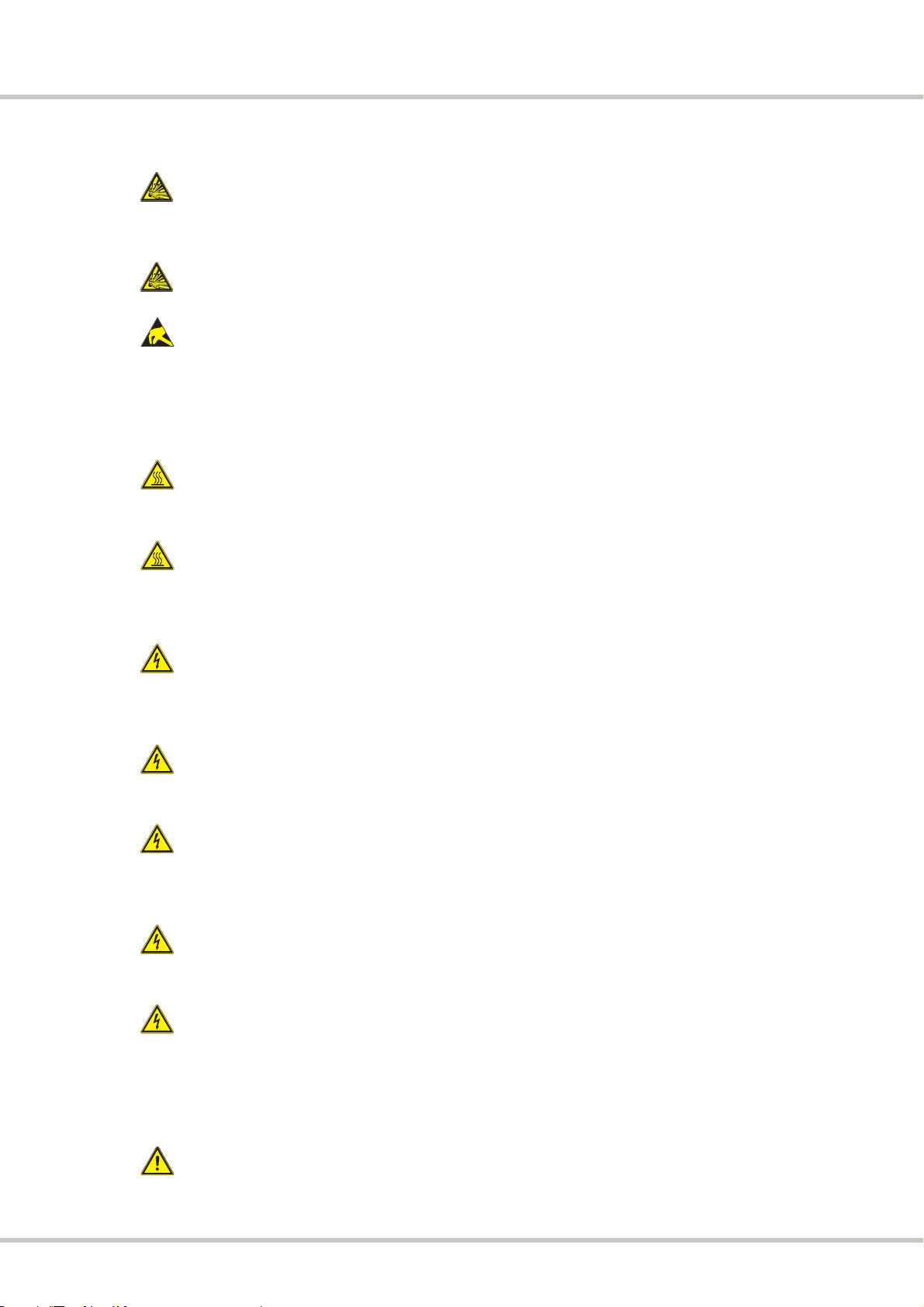
Advice symbol for danger in association with one of the signal words Precaution,
Warning or Danger.
Advice symbol for danger by electricity, in association with one of the signal words
Precaution, Warning or Danger.
Advice symbol for danger by electrostatic discharge, in association with one of the
signal words Precaution, Warning or Danger.
Advice symbol for danger by hot surface, in association with one of the signal words
Precaution, Warning or Danger.
Advice symbol for danger by explosion, in association with one of the signal words Pre
caution, Warning or Danger.
Advice symbol for corrosives in association with one of the signal words Precaution,
Warning or Danger.
Advice for the handling of the product.
An unexpected occurrence or condition could happen if this advice is disregarded.
Cross reference to other chapters.
1.4.2 List symbols
DList
-Subitem of a list
"Instruction which has only one step.
1. Instruction which has several steps. The steps must be executed in the stated order.
User Manual N10
About this User Manual
Industrial PC
3063-US-1.6 www.noax.com Page 9 of 84
1.5 Markings
Following markings are used in this document:
Marking Description
italic Emphasis
bold Product description or strong emphasis
Courier Term for software areas (GUI) and device labellings
1.6 Abbreviations and technical terms
Following abbreviations are used in this document:
Abkürzung Beschreibung
ALS Ambient Light Sensor
CFL Compact Fluorescent Light
CPU Central Processing Unit
GPRS General Packet Radio Service
HDU Hard Disk Unit
IMEI international Mobile Station Equipment Identity
MAC Media Access Control Address
SIM Subscriber Identity Module
UMTS Universal Mobile Telecommunications System
Windows Microsoft Windows operating system
WLAN Wireless Local Area Network
Following technical terms are used in this document:
Abkürzung Beschreibung
AHCI Advanced Host Controller Interface
GUI Graphical User Interface
MCU Micro Controller Unit
NCQ Native Command Queuing
PCI Peripheral Component Interface
PCIe Peripheral Component Interface express

User Manual N10
Intended use
Industrial PC
www.noax.comPage 10 of 84 3063-US-1.6
2 Intended use
Your Industrial PC has been manufactured according current technical standards and
complies with approved safety regulations.
The noax Industrial PC is suitable for recording operating and machine data, sup
porting personnel planning, streamlining commissioning, controlling machines or
visualizing production procedures.
Depending on the housing design of noax Industrial PC (see Chapter 5.1), it can be
fixed or mobile for use on vehicles or in hygienic and medical areas.
Any other use is not in compliance with its intended use. The user or operator of the
noax device is solely responsible for any resulting damage.This also applies to unaut
horized modifications to the device.
Use the Industrial PC only in flawless and undamaged condition.
3 Scope of delivery
Please check the content of this package for completeness according to the delivery
slip.
Please call the noax‐hotline if there are any discrepancies (see Chapter 4.8).
The packaging was developed especially for the noax Industrial PC to prevent shipping
damage. Please keep this packaging safe.
Please transport the Industrial PC in this packaging only.

User Manual N10
General safety information
Industrial PC
3063-US-1.6 www.noax.com Page 11 of 84
4 General safety information
Please follow the valid VDE/IEC/EN regulations while using products with electrical
voltage.
Warning
Repairs on Industrial PC devices should only be carried out by authorized personnel.
Warning
Basically do not repair the device on your own. Always contact our noax hotline and
send the device back for maintenance if necessary. Our service needs the important
device information on the label of the Industrial PC.
There are important information refering the features and production site of your devi
ce.
Please always inform the engineer about the complete code and serial number (see
Chapter 5.2 ).
4.1 Documentation
DTo avoid injury and damage, please read and observe the following usage and
safety information before initial operation.
DThe manufacturer/supplier is not liable for any damages caused by non‐compliance
with this information.
DThis manual must remain with the Industrial PC and be passed along with it
4.2 Handling with this device
DRespect the strong weight of some enclosures for handling and operation
DThe Industrial PC should only be used when it is fully functional and free of dama
ge!
Please change the device or the part especially when:
-the power cable or the mains plug is damaged
-there is an intrusion of liquid into the device enclosure
-there is a malfunction while using the device
-the enclosure is damaged
DMalfunctions that can affect safety (e.g. faulty power cable or enclosure) must be
immediately eliminated by you or a third party in accordance with specifications!
DEnsure that the electrical specifications on the attached label correspond to the
used power supply!
DBatteries:
Only use batteries of the same type, or similar types recommended by the manu
facturer.
For disposing please look at Chapter 15.
DIP65 (NEMA 4) protection:
Make sure that liquids and caustic vapors (e.g. from cleaning agents) are not able
to penetrate the interior of the IP65 protected electronics, especially regarding the
connector area.

User Manual N10
General safety information
Industrial PC
www.noax.comPage 12 of 84 3063-US-1.6
4.3 Enclosure S15‐G2, S19 and C19, C21 with option
integrated power supply
Use only the mains cable that was supplied with the S15‐G2, S19 and C19, C21 with
option integrated power supply IPCs, because only this cable ensure the locking
mechanism. Take care that the mains cable is not damaged.
4.4 External power supplies
DThe external power supply should not be opened for any reason. It does not con
tain any serviceable components.
DWhen attaching the power supply, only use the supplied mounting frame, or use the
available drill holes (do not attach to the cable). To avoid overheating, it should not
be covered or installed in an enclosure that is too small.
DThe power supply should only be connected to the mains supply using a protective
earth conductor. Only use the supplied power cable as it meets all important safety
regulations.
DThe Industrial PC should only be operated using the provided power supply or the
optional provided connection cable with integrated fuse.
4.5 External devices
DExternal devices (e.g. maintenance floppy, scanner...) should only be connected/di
sconnected to/from the Industrial PC when it is switched off. Otherwise, this could
damage the Industrial PC electronics or the external device itself. Wait at least five
seconds after switching off the Industrial PC before connecting an external device
(exception: Hot Plug devices connected to USB or Firewire ports).
DWhen connecting cables to the Industrial PC, make sure that there is no tensile
loading on the cable.
4.6 Safety information for selected countries
4.6.1 Norway
Warning
Utstyr som er koplet til beskyttelsesjord via nettplugg og/eller via annet jordtilkoplet utstyr ‐ og er
tilkoplet et kabel‐TV nett, kan forårsake brannfare. For å unngå dette skal det ved tilkopling av
utstyret til kabel‐TV nettet installeres en galvanisk isolator mellom utstyret og kabel‐TV nettet.
4.6.2 Sweden
Warning
Utrustning som är kopplad till skyddsjord via jordat vägguttag och/eller via annan utrustning och
samtidigt är kopplad till kabel‐TV nät kan i vissa fall medföra risk för brand. För att undvika detta
skall vid anslutning av utrustningen till kabel‐TV nät galvanisk isolator finnas mellan utrustningen
och kabel‐TV nätet.

User Manual N10
General safety information
Industrial PC
3063-US-1.6 www.noax.com Page 13 of 84
4.7 Cleaning information
Please refer to the information in Chapter 12 ”Maintenance and cleaning the Industri
al PC”
4.8 Upgrades and maintenance work on the
Industrial PC
The Industrial PC should only be opened by authorized personnel with basic knowled
ge of PCs. The warranty is voided by improper upgrades and maintenance work. When
in doubt, let our service department perform this work. Please contact our hotline
under:
Hotline Europe Hotline North America
Tel. +49 (0) 8092 8536 33
Fax +49 (0) 8092 8536 55
eMail: [email protected]
Tel. +1 704 992 1606
Fax +1 704 992 1712
eMail: [email protected]

User Manual N10
Enclosure and mainboard types
Industrial PC
www.noax.comPage 14 of 84 3063-US-1.6
5 Enclosure and mainboard types
5.1 Enclosure types
C12 - compact enclosure 12 inch
C15 - compact enclosure 15 inch
C19 - compact enclosure 19 inch

User Manual N10
Enclosure and mainboard types
Industrial PC
3063-US-1.6 www.noax.com Page 15 of 84
C21 - compact enclosure 21.5 inch
S12 - stainless steel enclosure 12 inch
S15 - stainless steel enclosure 15 inch
S15‐G2 - stainless steel enclosure 15 inch

User Manual N10
Enclosure and mainboard types
Industrial PC
www.noax.comPage 16 of 84 3063-US-1.6
S19 - stainless steel enclosure 19 inch
P15 - front installation enclosure 15 inch
5.2 Noax labels for Industrial‐PCs
C15, S12, S15, S15‐G2, S19 and P15

User Manual N10
Enclosure and mainboard types
Industrial PC
3063-US-1.6 www.noax.com Page 17 of 84
5.3 Noax label for Industrial‐PC C12, C19, C21
5.4 Information on the noax label
The type of your N10 mainboard is indicated on the rating plate e.g. N10For N10C.
Also the used type of display is indicated on the rating plate. (Extension S or X at the end of enclosure
type e.g. C12Soder C12X)
In addition to the serial number SN this label contains more important information:
DOptions, with those the IPC has been additionally equipped
DMAC1, address for LAN1 interface
DMAC2, address for LAN2 interface
DWLAN address
Differences between the types are descriped in the technical data in Chapter 14.
For further information please visit our website at www.noax.com
User Manual N10
Power supplies
Industrial PC
www.noax.comPage 18 of 84 3063-US-1.6
6 Power supplies
6.1 External table power supply
The following components are included in
shipment of the external table power
supply:
Dcountry‐specific Power supply cable
DPower supply with device cable
DMounting frame
Fig. 1: External table power supply
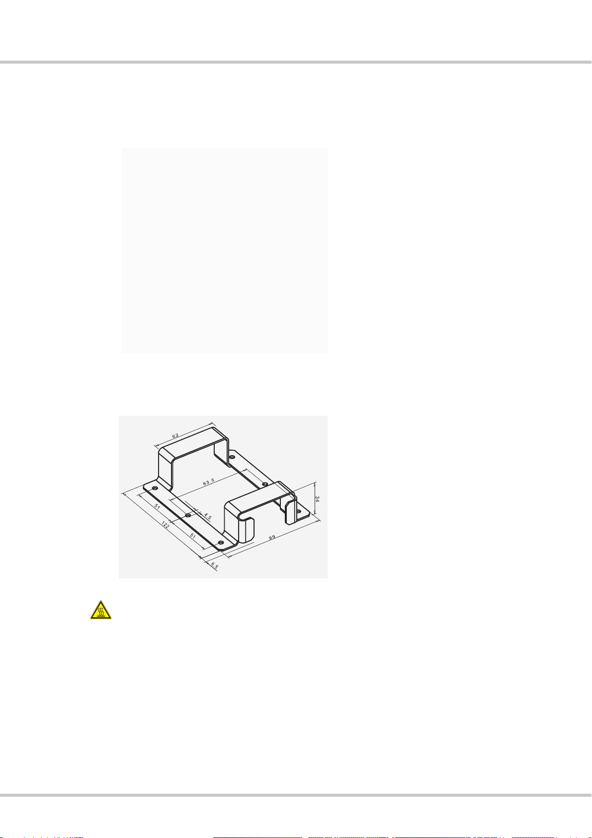
The mounting frame is used to hold the
table power supply. With the aid of the
fixing holes on the mounting frame, the
power supply can be mounted e.g. directly
onto the wall.
Fig. 2: Mounting frame (all dimensions in mm)
Warning
The power supply must not be positioned in the enclosure or in the plug area of the
Industrial PC. This would create a risk of overheating.

User Manual N10
Power supplies
Industrial PC
3063-US-1.6 www.noax.com Page 19 of 84
6.2 External power supply IP65 (NEMA 4)
The external power supply with protection
system IP65 (NEMA 4) can be attached
e.g. directly to the wall using the fixing
holes.
Fig. 3: External power supply IP65 (NEMA 4)
198
174
145
130
14. 5
4 . 5
m i n . 2 2 0
144
To install the external power supply, copy
the drilling spacing shown in the drawing
to the wall onto which you wish to attach
the equipment.
Fig. 4: Fixing holes (all dimensions in mm)
User Manual N10
Safety notes for initial operation
Industrial PC
www.noax.comPage 20 of 84 3063-US-1.6
7 Safety notes for initial operation
Danger
An explosion hazard will be created if the CMOS battery (type CR2032,
-40°C(-40°F)/+80°C(176°F)) is installed incorrectly. Install the battery with the ”+” sign
up (the ”+” sign must be visible after installation).
Danger
Do not use the Industrial PC in explosive environment.
Warning
These devices contain electronic components with highly integrated modules or modu
lar elements. These electronic components are highly sensitive to surges as well as the
discharge of static electricity. To avoid damage, you should discharge the static electri
city from your body before handling any system components. When working on elec
tronic components, please use an approved ESD wristband.
Warning
The power supply must not be positioned in the enclosure or in the plug area of the
Industrial PC.This would create a risk of overheating.
Warning
When opening the device, please be aware that some parts and components become
hot during operation (e.g. memory). These components should be allowed to cool
before being handled.
Danger
Repairs to electronic devices should only be carried out by authorized personnel.
Improper work on electrical and electronic devices could cause life‐threatening electric
shocks.
Danger
Faulty and damaged electrical equipment and parts should only be replaced by autho
rized electricians.
Warning
It is required for enclosure types S15‐G2, S19 and C19, C21 with option integrated
power supply to execute the check according to DIN VDE 0701 / 0702 in periodic
intervals and after working nearby the internal power supply.
Warning
Make sure that there is no potential equalization through the device. (e.g. by ground
loops)
Precaution
The power supply (enclosure types C12, C19, C21, S12, C15, S15, P15) or the device
itself (enclosure type S15‐G2, S19 and C19, C21 with option integrated power supply)
must be installed in such a way to allow disconnection from the mains supply at any
time. The mains plug of the respective countries is used as disconnect device. The
socket‐outlet must be installed near the equipment and must be easily accessible.
Danger
Risk of electronic influence: Without a permission, it is not allowed to switch on the
Industrial PC in airplanes, hospitals or other medical environments.
This manual suits for next models
2
Table of contents
Other noax Industrial PC manuals


Popular Industrial PC manuals by other brands

Psion Teklogix
Psion Teklogix 8525 user manual

Shuttle
Shuttle DH670 user manual

SYSTEM Electronics
SYSTEM Electronics COPILOT PB user manual

Moxa Technologies
Moxa Technologies DA-681-I-SP-CE Quick installation guide

Acrosser Technology
Acrosser Technology ACS-N0831FLUD installation guide

Shuttle
Shuttle P21WL01 quick start guide


