B&R Power Panel C80 User manual

Power Panel C80
User's manual
Version: 1.02 (April 2021)
Order no.: MAPPC80-EN
Translation of the original documentation

Publishing information
B&R Industrial Automation GmbH
B&R Strasse 1
5142 Eggelsberg
Austria
Telephone: +43 7748 6586-0
Fax: +43 7748 6586-26
Disclaimer
All information in this manual is current as of its creation. The contents of this manual are subject to change without
notice. B&R Industrial Automation GmbH assumes unlimited liability in particular for technical or editorial errors
in this manual only (i) in the event of gross negligence or (ii) for culpably inflicted personal injury. Beyond that,
liability is excluded to the extent permitted by law. Liability in cases in which the law stipulates mandatory unlimited
liability (such as product liability) remains unaffected. Liability for indirect damage, consequential damage, business
interruption, loss of profit or loss of information and data is excluded, in particular for damage that is directly or
indirectly attributable to the delivery, performance and use of this material.
B&R Industrial Automation GmbH notes that the software and hardware designations and brand names of the
respective companies used in this document are subject to general trademark, brand or patent protection.
Hardware and software from third-party suppliers referenced in this manual is subject exclusively to the respective
terms of use of these third-party providers. B&R Industrial Automation GmbH assumes no liability in this regard.
Any recommendations made by B&R Industrial Automation GmbH are not contractual content, but merely non-
binding information for which no liability is assumed. When using hardware and software from third-party suppliers,
the relevant manuals of these third-party suppliers must additionally be consulted and, in particular, the safety
guidelines and technical specifications contained therein must be observed. The compatibility of the products from
B&R Industrial Automation GmbH described in this manual with hardware and software from third-party suppliers
is not contractual content unless this has been separately agreed in individual cases; in this respect, warranty for
such compatibility is excluded in any case, and it is the sole responsibility of the customer to verify this compatibility
in advance.
1580038124922-1.02.2

Table of contents
1 Introduction................................................................................................................6
1.1 Manual history.................................................................................................................................................6
1.2 Information about this document.................................................................................................................... 6
1.2.1 Organization of notices..............................................................................................................................6
1.2.2 Guidelines.................................................................................................................................................. 6
2 General safety guidelines........................................................................................ 7
2.1 Intended use................................................................................................................................................... 7
2.2 Protection against electrostatic discharge...................................................................................................... 7
2.2.1 Packaging.................................................................................................................................................. 7
2.2.2 Regulations for proper ESD handling....................................................................................................... 7
2.3 Regulations and measures............................................................................................................................. 7
2.4 Transport and storage.................................................................................................................................... 8
2.5 Installation....................................................................................................................................................... 8
2.6 Operation.........................................................................................................................................................8
2.6.1 Protection against contact with electrical parts.........................................................................................8
2.6.2 Ambient conditions - Dust, moisture, aggressive gases........................................................................... 8
2.6.3 Programs, viruses and malicious programs..............................................................................................9
2.7 Cybersecurity disclaimer for products............................................................................................................ 9
3 System overview..................................................................................................... 10
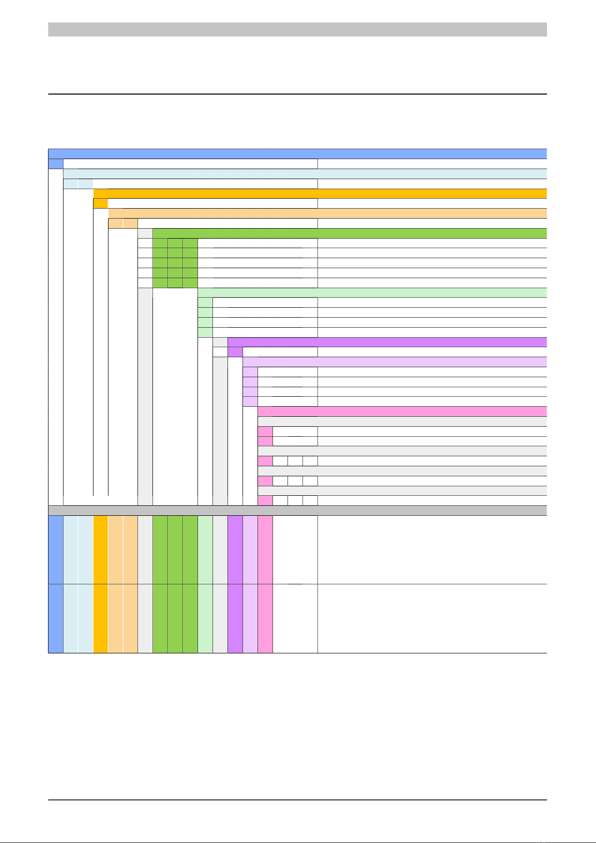
3.1 Order number key.........................................................................................................................................10
3.2 System characteristics.................................................................................................................................. 11
3.2.1 Type overview..........................................................................................................................................11
3.3 Overview........................................................................................................................................................11
4 Device description.................................................................................................. 12
4.1 Order overview..............................................................................................................................................12
4.1.1 Content of delivery.................................................................................................................................. 12
4.1.2 Optional accessories............................................................................................................................... 12
4.2 Technical data...............................................................................................................................................13
4.2.1 Specific technical data of the display variants........................................................................................ 15
4.2.2 Technical data of the interface variants.................................................................................................. 16
4.3 Technical information.................................................................................................................................... 17
4.3.1 Dependencies to hardware upgrades and Automation Runtime............................................................ 17
4.3.2 Practical example of writing load in an application................................................................................. 17
4.3.3 Projected capacitive touch (PCT)............................................................................................................17
4.3.4 Viewing angles........................................................................................................................................ 18
4.3.5 Surface resistance...................................................................................................................................18
4.4 Temperature/Humidity diagrams...................................................................................................................19
4.5 Dimensions....................................................................................................................................................22
4.5.1 5.7" variants.............................................................................................................................................22
4.5.2 7.0" variants.............................................................................................................................................23
4.5.3 10.1" variants...........................................................................................................................................24
4.5.4 12.1" variants...........................................................................................................................................25
4.5.5 15.6" variants...........................................................................................................................................26
4.6 Environmental properties.............................................................................................................................. 27
4.6.1 Spacing for air circulation........................................................................................................................27
4.6.2 Temperature sensor positions.................................................................................................................28
4.6.3 Derating the ambient temperature.......................................................................................................... 28
4.7 Device interfaces and slots...........................................................................................................................29
4.7.1 Interface overview................................................................................................................................... 29
4.7.2 Power supply........................................................................................................................................... 29
4.7.3 Grounding................................................................................................................................................ 30
4.7.4 USB interfaces.........................................................................................................................................30
4.7.5 LED status indicators.............................................................................................................................. 31
4.7.6 Fieldbus interfaces.................................................................................................................................. 32
Power Panel C80 User's manual V1.02 3

Table of contents
4.7.7 Reset button............................................................................................................................................ 32
4.7.8 Ethernet interface (IF2)........................................................................................................................... 33
4.7.9 POWERLINK interface (IF1)................................................................................................................... 33
4.7.10 Battery....................................................................................................................................................34
4.8 Product information....................................................................................................................................... 35
5 Installation and wiring............................................................................................ 36
5.1 Basic information...........................................................................................................................................36
5.2 Requirements for the installation cutout....................................................................................................... 37
5.2.1 Installation cutout.....................................................................................................................................37
5.3 Installing with retaining clips......................................................................................................................... 39
5.4 Installing with a VESA bracket..................................................................................................................... 40
5.5 Mounting orientations....................................................................................................................................41
5.6 Grounding (functional ground)...................................................................................................................... 42
5.7 Securing the connecting cables....................................................................................................................43
5.8 Requirements for the cables used................................................................................................................44
6 Software................................................................................................................... 45
6.1 Operating systems........................................................................................................................................ 45
6.1.1 B&R Hypervisor....................................................................................................................................... 45
6.1.2 Automation Runtime................................................................................................................................ 46
6.2 Configuration in Automation Studio.............................................................................................................. 47
6.2.1 Standard options..................................................................................................................................... 47
6.2.2 Terminal configuration............................................................................................................................. 47
6.2.3 NAT configuration.................................................................................................................................... 52
6.2.4 VNC server configuration for PLC.......................................................................................................... 53
6.3 Boot options.................................................................................................................................................. 54
6.3.1 Startup procedure....................................................................................................................................54
6.3.2 Boot menu............................................................................................................................................... 55
6.3.3 Boot manager.......................................................................................................................................... 55
6.4 Updating/Installing the C80 system.............................................................................................................. 56
6.4.1 B&R Hypervisor system.......................................................................................................................... 56
6.4.2 Terminal OS (embedded Linux) system................................................................................................. 57
6.5 Viewing license information.......................................................................................................................... 59
6.6 Network information...................................................................................................................................... 60
6.7 Web browser information..............................................................................................................................60
6.7.1 Supported fonts....................................................................................................................................... 60
6.7.2 Supported video formats......................................................................................................................... 60
6.7.3 User agent............................................................................................................................................... 61
6.7.4 Using the developer tools....................................................................................................................... 61
6.7.5 Keyboard..................................................................................................................................................62
6.8 File formats................................................................................................................................................... 63
6.8.1 Terminal OS image..................................................................................................................................63
6.8.2 Boot logo................................................................................................................................................. 63
6.8.3 Boot animation.........................................................................................................................................63
7 Commissioning........................................................................................................64
7.1 Basic information...........................................................................................................................................64
7.2 Calibration..................................................................................................................................................... 64
7.3 Operating the Power Panel.......................................................................................................................... 64
7.3.1 Keyboard..................................................................................................................................................64
7.3.2 Mouse...................................................................................................................................................... 64
8 Maintenance.............................................................................................................65
8.1 Changing the battery.................................................................................................................................... 65
8.2 Cleaning........................................................................................................................................................ 67
8.3 Pixel errors....................................................................................................................................................67
4 Power Panel C80 User's manual V1.02

Table of contents
8.4 User tips for increasing the display's service life......................................................................................... 67
8.4.1 Backlight.................................................................................................................................................. 67
8.4.2 Screen burn-in......................................................................................................................................... 67
8.5 Repairs/Complaints and replacement parts..................................................................................................68
9 Accessories............................................................................................................. 69
9.1 0TB6102 2-pin power supply connector.......................................................................................................69
9.1.1 Order data............................................................................................................................................... 69
9.1.2 Technical data......................................................................................................................................... 69
9.2 0TB1210.3100............................................................................................................................................... 70
9.2.1 General information................................................................................................................................. 70
9.2.2 Order data............................................................................................................................................... 70
9.2.3 Technical data......................................................................................................................................... 70
9.3 Replacement parts........................................................................................................................................ 71
9.3.1 5ACCRHMI.0018-000 - Technical data...................................................................................................71
9.4 Cable accessories.........................................................................................................................................71
10 International and national certifications.............................................................72
10.1 Directives and declarations.........................................................................................................................72
10.1.1 CE marking............................................................................................................................................72
10.1.2 EMC Directive........................................................................................................................................72
10.2 Certifications................................................................................................................................................73
10.2.1 UL certification.......................................................................................................................................73
10.2.2 EAC........................................................................................................................................................73
10.2.3 KC.......................................................................................................................................................... 73
10.2.4 RCM.......................................................................................................................................................73
11 Environmentally friendly disposal.......................................................................74
11.1 Separation of materials............................................................................................................................... 74
Power Panel C80 User's manual V1.02 5

Introduction
1 Introduction
Information:
B&R makes every effort to keep documents as current as possible. The most current versions can be
downloaded from the B&R website (www.br-automation.com).
1.1 Manual history
Version Date Comment
1.02 April 2021 Updated the following chapters:
•Boot options
•Updating/Installing the C80 system
Updated the following chapters:
•Viewing license information
•Network information
1.01 April 2021 Editorial adjustments.
Updated the following chapters:
•"Order number key" on page 10 (added customized coding)
•"Dependencies to hardware upgrades and Automation Runtime" on page 17 (more detailed listing)
•"LED status indicators" on page 31 (color/description correction)
•"Fieldbus interfaces" on page 32
1.00 March 2021 First version
1.2 Information about this document
This document is not intended for end customers! The safety guidelines required for end customers
must be incorporated into the operating instructions for end customers in the respective national lan-
guage by the machine manufacturer or system provider.
1.2.1 Organization of notices
Safety notices
Contain only information that warns of dangerous functions or situations.
Signal word Description
Danger! Failure to observe these safety guidelines and notices will result in death, severe injury or substantial damage to property.
Warning! Failure to observe these safety guidelines and notices can result in death, severe injury or substantial damage to property.
Caution! Failure to observe these safety guidelines and notices can result in minor injury or damage to property.
Notice! Failure to observe these safety guidelines and notices can result in damage to property.
General notices
Contain useful information for users and instructions for avoiding malfunctions.
Signal word Description
Information: Useful information, application tips and instructions for avoiding malfunctions.
1.2.2 Guidelines
European dimension standards apply to all dimension diagrams.
All dimensions in millimeters.
Unless otherwise specified, the following general tolerances apply:
Nominal dimension range General tolerance per
DIN ISO 2768 medium
Up to 6 mm ±0.1 mm
Over 6 to 30 mm ±0.2 mm
Over 30 to 120 mm ±0.3 mm
Over 120 to 400 mm ±0.5 mm
Over 400 to 1000 mm ±0.8 mm
6 Power Panel C80 User's manual V1.02

General safety guidelines
2 General safety guidelines
2.1 Intended use
Programmable logic controllers, operating and monitoring devices (e.g. industrial PCs, Power Panels, Mobile Pan-
els) as well as uninterruptible power supplies from B&R have been designed, developed and manufactured for
normal use in industry. They have not been designed, developed and manufactured for use that involves fatal
risks or hazards that could result in death, injury, serious physical harm or other loss without the assurance of
exceptionally stringent safety precautions. In particular, this includes the use of these systems to monitor nuclear
reactions in nuclear power plants, flight control systems, air traffic control, the control of mass transport vehicles,
medical life support systems and the control of weapon systems.
2.2 Protection against electrostatic discharge
Electrical assemblies that can be damaged by electrostatic discharge (ESD) must be handled accordingly.
2.2.1 Packaging
•Electrical assemblies with housing:
Do not require special ESD packaging but must be handled properly (see "Electrical assemblies with hous-
ing").
•Electrical assemblies without housing:
Are protected by ESD-suitable packaging.
2.2.2 Regulations for proper ESD handling
Electrical assemblies with housing
•Do not touch the connector contacts of connected cables.
•Do not touch the contact tips on circuit boards.
Electrical assemblies without housing
The following applies in addition to "Electrical assemblies with housing":
•All persons handling electrical assemblies and devices in which electrical assemblies are installed must
be grounded.
•Assemblies are only permitted to be touched on the narrow sides or front plate.
•Always place assemblies on suitable surfaces (ESD packaging, conductive foam, etc.). Metallic surfaces
are not suitable surfaces!
•Assemblies must not be subjected to electrostatic discharges (e.g. due to charged plastics).
•A minimum distance of 10 cm from monitors or television sets must be maintained.
•Measuring instruments and devices must be grounded.
•Test probes of floating potential measuring instruments must be discharged briefly on suitable grounded
surfaces before measurement.
Individual components
•ESD protective measures for individual components are implemented throughout B&R (conductive floors,
shoes, wrist straps, etc.).
•The increased ESD protective measures for individual components are not required for handling B&R
products at customer locations.
2.3 Regulations and measures
Electronic devices are generally not failsafe. If the programmable logic controller, operating or control device or
uninterruptible power supply fails, the user is responsible for ensuring that connected devices (such as motors)
are brought to a safe state.
Power Panel C80 User's manual V1.02 7

General safety guidelines
When using programmable logic controllers as well as when using operating and monitoring devices as control
systems in conjunction with a Soft PLC (e.g. B&R Automation Runtime or similar product) or Slot PLC (e.g. B&R
LS251 or similar product), the safety measures that apply to industrial controllers (protection by protective equip-
ment such as emergency stops) must be observed in accordance with applicable national and international regu-
lations. This also applies to all other connected devices, such as drives.
All work such as installation, commissioning and servicing are only permitted to be carried out by qualified person-
nel. Qualified personnel are persons who are familiar with the transport, installation, assembly, commissioning and
operation of the product and have the appropriate qualifications for their job (e.g. IEC 60364). National accident
prevention regulations must be observed.
The safety guidelines, information about connection conditions (nameplate and documentation) and limit values
specified in the technical data must be read carefully before installation and commissioning and must be strictly
observed.
2.4 Transport and storage
During transport and storage, devices must be protected against undue stress (mechanical stress, temperature,
humidity, aggressive atmosphere).
2.5 Installation
•The devices are not ready for use and must be installed and wired according to the requirements of this
documentation in order to comply with EMC limit values.
•Installation must be carried out according to the documentation using suitable equipment and tools.
•Devices are only permitted to be installed in a voltage-free state and by qualified personnel. The control
cabinet must first be disconnected from the power supply and secured against being switched on again.
•General safety regulations and national accident prevention regulations must be observed.
•The electrical installation must be carried out in accordance with relevant regulations (e.g. line cross section,
fuse protection, protective ground connection).
2.6 Operation
2.6.1 Protection against contact with electrical parts
In order to operate programmable logic controllers, operating and monitoring devices and uninterruptible power
supplies, it is necessary for certain components to carry dangerous voltages over 42 VDC. Touching one of these
components can result in a life-threatening electric shock. There is a risk of death, serious injury or damage to
property.
Before switching on programmable logic controllers, operating and monitoring devices and uninterruptible power
supplies, it must be ensured that the housing is properly connected to ground potential (PE rail). Ground connec-
tions must also be made if the operating and monitoring device and uninterruptible power supply are only connect-
ed for testing purposes or only operated for a short time!
Before switching on, live parts must be securely covered. All covers must be kept closed during operation.
2.6.2 Ambient conditions - Dust, moisture, aggressive gases
The use of operating and monitoring devices (e.g. industrial PCs, Power Panels, Mobile Panels) and uninterruptible
power supplies in dusty environments must be avoided. This can otherwise result in dust deposits that affect the
functionality of the device, especially in systems with active cooling (fans), which may no longer ensure sufficient
cooling.
The presence of aggressive gases in the environment can also result in malfunctions. In combination with high
temperature and relative humidity, aggressive gases – for example with sulfur, nitrogen and chlorine components
– trigger chemical processes that can very quickly impair or damage electronic components. Blackened copper
surfaces and cable ends in existing installations are indicators of aggressive gases.
When operated in rooms with dust and condensation that can endanger functionality, operating and monitoring
devices such as Automation Panels or Power Panels are protected on the front against the ingress of dust and
moisture when installed correctly (e.g. cutout installation). The back of all devices must be protected against the
ingress of dust and moisture, however, or the dust deposits must be removed at suitable intervals.
8 Power Panel C80 User's manual V1.02

General safety guidelines
2.6.3 Programs, viruses and malicious programs
Any data exchange or installation of software using data storage media (e.g. floppy disk, CD-ROM, USB flash
drive) or via networks or the Internet poses a potential threat to the system. It is the direct responsibility of the user
to avert these dangers and to take appropriate measures such as virus protection programs and firewalls to protect
against them and to use only software from trustworthy sources.
2.7 Cybersecurity disclaimer for products
B&R products communicate via a network interface and were developed for secure connection with internal and,
if necessary, other networks such as the Internet.
Information:
In the following, B&R products are referred to as "product" and all types of networks (e.g. internal
networks and the Internet) are referred to as "network".
It is the sole responsibility of the customer to establish and continuously ensure a secure connection between
the product and the network. In addition, appropriate security measures must be implemented and maintained
to protect the product and entire network from any security breaches, unauthorized access, interference, digital
intrusion, data leakage and/or theft of data or information.
B&R Industrial Automation GmbH and its subsidiaries are not liable for damages and/or losses in connection
with security breaches, unauthorized access, interference, digital intrusion, data leakage and/or theft of data or
information.
The aforementioned appropriate security measures include, for example:
•Segmentation of the network (e.g. separation of the IT network from the control network1))
•Use of firewalls
•Use of authentication mechanisms
•Encryption of data
•Use of anti-malware software
Before B&R releases products or updates, they are subjected to appropriate functional testing. Independently of
this, we recommend that our customers develop their own test processes in order to be able to check the effects
of changes in advance. Such changes include, for example:
•Installation of product updates
•Significant system modifications such as configuration changes
•Deployment of updates or patches for third-party software (non-B&R software)
•Hardware replacement
These tests should ensure that implemented security measures remain effective and that systems in the customer's
environment behave as expected.
1) The term "control network" refers to computer networks used to connect control systems. The control network can be divided into zones, and there can be
several separate control networks within a company or site. The term "control systems" refers to all types of B&R products such as controllers (e.g. X20), HMI
systems (e.g. Power Panel T30), process control systems (e.g. APROL) and supporting systems such as engineering workstations with Automation Studio.
Power Panel C80 User's manual V1.02 9

System overview
3 System overview
3.1 Order number key
Product area
4 Embedded PC-based automation
Product family
P P Power Panel
Model
C Controller series
Variant
8 0 Intel processor (Atom E3940, quad core)
Diagonal
. 0 5 7 5.7"
. 0 7 0 7.0"
. 1 0 1 10.1"
. 1 2 1 12.1"
. 1 5 6 15.6"
Resolution
2 WVGA (800 x 480)
3 VGA (640 x 480)
B HD (1366 x 768)
E WXGA (1280 x 800)
Display / Touch screen technology
- 1 TFT color + multi-touch PCT (glass)
Optional interfaces and features
0 Standard / No additional interface
1 2x CAN
2 1x RS232, 1x CAN
3 1x RS485, 1x CAN
Front design
Standard variants
B Black, clear glass
A Black, anti-glare glass
Industry-specific variant
I . . . Seq. number: I[0...Z][0...Z][0...Z]
Customized panel overlay only
F . . . Seq. number: F[0...Z][0...Z][0...Z]
Completely customized variant
G . . . Seq. number: C[0...Z][0...Z][0...Z]
Examples
4 P P C 8 0 . 0 5 7 3 - 1 1 B
Power Panel C80, glass front, controller with mapp View HMI unit, fieldbus
interfaces: 2x CAN bus. CPU and memory of the controller: 1600 MHz
(Intel Atom E3940), 4 GB DRAM, 32 kB FRAM, 4 GB onboard flash drive.
Display and touch screen: 5.7", 640 x 480 (VGA) resolution, projected
capacitive touch screen, multi-touch support, glass front with black frame,
landscape and portrait format configurable using software. Interfaces: 1x
POWERLINK, 1x Ethernet 10/100/1000 Mbit/s, 1x X2X Link, 2x USB 3.0,
2x CAN bus.
4 P P C 8 0 . 1 2 1 E - 1 3 A
Power Panel C80, 12.1", glass front (anti-glare), fieldbus interfaces: 1x
CAN bus, 1x RS485. CPU and memory: 1600 MHz (Intel Atom E3940),
4 GB DRAM, 64 kB FRAM, 4 GB onboard flash drive. Display and touch
screen: 12.1", 1280 x 800 (WXGA) resolution, projected capacitive touch
screen, multi-touch support, anti-glare glass front with black frame, land-
scape and portrait format configurable with software. Interfaces: 1x POW-
ERLINK, 1x Ethernet 10/100/1000 Mbit/s, 1x X2X Link, 2x USB 3.0, 1x
CAN bus, 1x RS485.
10 Power Panel C80 User's manual V1.02

System overview
3.2 System characteristics
3.2.1 Type overview
Panel size 5.7" 7.0"10.1"12.1" 15.6"
4PPC80.0573-1xx 4PPC80.0702-1xx 4PPC80.101E-1xx 4PPC80.121E-1xx 4PPC80.156B-1xxOrder number
Format/Resolution Landscape/Portrait format
Resolution VGA
640 x 480
WVGA
800 x 480
WXGA
1280 x 800
WXGA
1280 x 800
HD
1366 x 768
05730702101E121E156B
Order number 4PPC80.xxxx-xxx
Technology
TFT color + multi-touch PCT (glass)
Order number 4PPC80.xxxx-1xx
The following interface variants are available for the five display sizes:
4PPC80.xxxx-x0x
Interfaces 0123
IF1: POWERLINK ● ● ● ●
IF2: Ethernet ● ● ● ●
IF4: USB ● ● ● ●
IF5: USB ● ● ● ●
IF6: X2X ● ● ● ●
IF7: CAN bus ● ● ●
IF8: CAN bus ●
IF9: RS232 ●
IF10: RS485 ●
The following interface variants are available for the five display sizes:
Order number 4PPC80.xxxx-xxA 4PPC80.xxxx-xxB
General information
Light transmission 70% -
Display
Touch screen
Surface Glass, chemically hardened (6H), anti-glare Glass, chemically hardened (6H)
3.3 Overview
Order number Short description Page
Accessories
5ACCRHMI.0018-000 HMI C80/PPC1200 battery compartment - 1x battery holder C80/PPC1200 - 1x battery including circuit board 71
Terminal blocks
0TB1210.3100 Connector 300 VDC - 10-pin female - Cage clamp terminal block - Protected against vibration by the screw
flange
70
0TB6102.3000-00 2-pin accessory screw clamp terminal block (3.81) 69
0TB6102.3100-00 Accessory 2-pin cage clamp terminal block (3.81) 69
Power Panel C80 User's manual V1.02 11

Device description
4 Device description
4.1 Order overview
Order number Display Front IF7 IF8 IF9 IF10
4PPC80.0573-10A 5.7" Glass, chemically hardened (6H), anti-glare
4PPC80.0573-10B 5.7" Glass, chemically hardened (6H)
4PPC80.0573-11A 5.7" Glass, chemically hardened (6H), anti-glare CAN bus CAN bus
4PPC80.0573-11B 5.7" Glass, chemically hardened (6H) CAN bus CAN bus
4PPC80.0573-12A 5.7" Glass, chemically hardened (6H), anti-glare CAN bus RS232
4PPC80.0573-12B 5.7" Glass, chemically hardened (6H) CAN bus RS232
4PPC80.0573-13A 5.7" Glass, chemically hardened (6H), anti-glare CAN bus RS485
4PPC80.0573-13B 5.7" Glass, chemically hardened (6H) CAN bus RS485
4PPC80.0702-10A 7.0" Glass, chemically hardened (6H), anti-glare
4PPC80.0702-10B 7.0" Glass, chemically hardened (6H)
4PPC80.0702-11A 7.0" Glass, chemically hardened (6H), anti-glare CAN bus CAN bus
4PPC80.0702-11B 7.0" Glass, chemically hardened (6H) CAN bus CAN bus
4PPC80.0702-12A 7.0" Glass, chemically hardened (6H), anti-glare CAN bus RS232
4PPC80.0702-12B 7.0" Glass, chemically hardened (6H) CAN bus RS232
4PPC80.0702-13A 7.0" Glass, chemically hardened (6H), anti-glare CAN bus RS485
4PPC80.0702-13B 7.0" Glass, chemically hardened (6H) CAN bus RS485
4PPC80.101E-10A 10.1" Glass, chemically hardened (6H), anti-glare
4PPC80.101E-10B 10.1" Glass, chemically hardened (6H)
4PPC80.101E-11A 10.1" Glass, chemically hardened (6H), anti-glare CAN bus CAN bus
4PPC80.101E-11B 10.1" Glass, chemically hardened (6H) CAN bus CAN bus
4PPC80.101E-12A 10.1" Glass, chemically hardened (6H), anti-glare CAN bus RS232
4PPC80.101E-12B 10.1" Glass, chemically hardened (6H) CAN bus RS232
4PPC80.101E-13A 10.1" Glass, chemically hardened (6H), anti-glare CAN bus RS485
4PPC80.101E-13B 10.1" Glass, chemically hardened (6H) CAN bus RS485
4PPC80.121E-10A 12.1" Glass, chemically hardened (6H), anti-glare
4PPC80.121E-10B 12.1" Glass, chemically hardened (6H)
4PPC80.121E-11A 12.1" Glass, chemically hardened (6H), anti-glare CAN bus CAN bus
4PPC80.121E-11B 12.1" Glass, chemically hardened (6H) CAN bus CAN bus
4PPC80.121E-12A 12.1" Glass, chemically hardened (6H), anti-glare CAN bus RS232
4PPC80.121E-12B 12.1" Glass, chemically hardened (6H) CAN bus RS232
4PPC80.121E-13A 12.1" Glass, chemically hardened (6H), anti-glare CAN bus RS485
4PPC80.121E-13B 12.1" Glass, chemically hardened (6H) CAN bus RS485
4PPC80.156B-10A 15.6" Glass, chemically hardened (6H), anti-glare
4PPC80.156B-10B 15.6" Glass, chemically hardened (6H)
4PPC80.156B-11A 15.6" Glass, chemically hardened (6H), anti-glare CAN bus CAN bus
4PPC80.156B-11B 15.6" Glass, chemically hardened (6H) CAN bus CAN bus
4PPC80.156B-12A 15.6" Glass, chemically hardened (6H), anti-glare CAN bus RS232
4PPC80.156B-12B 15.6" Glass, chemically hardened (6H) CAN bus RS232
4PPC80.156B-13A 15.6" Glass, chemically hardened (6H), anti-glare CAN bus RS485
4PPC80.156B-13B 15.6" Glass, chemically hardened (6H) CAN bus RS485
4.1.1 Content of delivery
Order number Description
0TB6102.3100-00 Accessory terminal block, 2-pin (3.81), cage clamp terminal block, 1.5 mm²
0TB1210.3100 Accessory terminal block, 10-pin (3.5), cage clamp terminal block, 1.5 mm²
Retaining clips Accessory set of retaining clips for mounting the panel
Accessory plate Plate for securing / strain relief of the connection lines and connecting the shield
4.1.2 Optional accessories
Order number Description
0TB6102.3000-00 Accessory terminal block, 2-pin (3.81), screw clamp terminal block, 1.5 mm²
12 Power Panel C80 User's manual V1.02

Device description
4.2 Technical data
General technical data
Order number 4PPC80.xxxx-xxx
General information
Cooling Passive
Power button No
Reset button Yes
Status indicators Operating state, terminating resistor LEDs, interface status
Buzzer No
Support
mapp View Yes
Controller redundancy possible No
Visual Components support Yes
Controller
Real-time clock 1) Nonvolatile, resolution 1 s
Processor
Type Intel Atom x5-E3940
Clock frequency 1600 MHz
Number of cores 4
Architecture 14 nm
Thermal design power (TDP) 9.5 W
L1 cache
Data code 32 kB
Program code 32 kB
L2 cache 2 MB
Intel 64 architecture Yes
Intel Hyper-Threading Technology No
Intel vPro Technology No
Intel Virtualization Technology (VT-x) Yes
Intel Virtualization Technology for Directed I/O
(VT-d)
Yes
Enhanced Intel SpeedStep Technology Yes
Mode/Node switches No
Remanent variables 64 kB FRAM, retention >10 years 2)
Shortest task class cycle time 0.4 ms
Typical instruction cycle time 0.01 µs
Chipset Apollo Lake
Real-time clock
Accuracy At 25°C: Typ. 12 ppm (1 second) per day 3)
Self-discharge time Approx. 8 years
Battery-backed Yes
Memory
Type LPDDR4 SDRAM
Memory size 4 GB
Velocity DDR4L-2133
Memory interface width Dual channel
Removable No
Graphics
Controller Intel HD Graphics
Max. dynamic graphics frequency 600 MHz
Color depth Max. 32-bit
DirectX support 12
OpenGL support 4.3
Application memory
Type Flash memory 5 GB NVMe pSLC
Data retention 10 years
Writable data amount
Theoretical 150 TBW
Client workload 90 TBW 4)
Error-correcting code (ECC) Yes
Power management ACPI 5.0
Interfaces
Interface IF1
Fieldbus POWERLINK V2 managing or controlled node
Type Type 4 5)
Variant 1x RJ45 shielded
Line length Max. 100 m between 2 nodes (segment length)
Max. transfer rate 100 Mbit/s
Power Panel C80 User's manual V1.02 13

Device description
Order number 4PPC80.xxxx-xxx
Interface IF2
Type Ethernet
Variant 1x RJ45 shielded
Line length Max. 100 m between 2 nodes (segment length)
Max. transfer rate 10/100/1000 Mbit/s
Transfer
Physical layer 10BASE-T/100BASE-TX/1000BASE-T
Half-duplex Yes
Full-duplex Yes
Autonegotiation Yes
Auto-MDI/MDIX Yes
Interface IF3
Variant Internal Ethernet interface
Interface IF4
Type USB 3.0
Variant Type A
Current-carrying capacity 1 A
Interface IF5
Fieldbus USB 3.0
Variant Type A
Current-carrying capacity 1 A
Interface IF6
Fieldbus X2X Link master
Max. distance Max. 100 m between 2 nodes (segment length)
Operating conditions
Permissible mounting orientations 6)
Standard mounting orientation Vertical
Rotation In 90° increments (portrait/landscape)
Degree of protection per EN 60529 In preparation: Front: IP65, Back: IP20
Ambient conditions
Elevation
Operation Max. 3000 m 7)
Mechanical properties
Front
Design Black
1) The real-time clock is backed up by a battery.
2) The memory size for remanent variables is configurable in Automation Studio. Permanent variables are not supported.
3) At max. specified ambient temperature: Typ. 58 ppm (5 seconds) - worst case 220 ppm (19 seconds).
4) TBW = Terabytes written
5) See section "Communication → POWERLINK → General information → Hardware - IF/LS" in Automation Help
6) For details, see section "Installation and wiring".
7) The maximum ambient temperature is typically derated 1°C per 1000 meters starting at 500 m above sea level.
Ambient conditions
Order number 4PPC80.0573-xxx 4PPC80.0702-xxx 4PPC80.101E-xxx 4PPC80.121E-xxx 4PPC80.156B-xxx
Ambient conditions
Temperature
Operation -20 to 60°C 1)
Storage -20 to 80°C -20 to 70°C
Transport -20 to 80°C -20 to 70°C
Relative humidity See section "Temperature/Humidity diagrams".
1) The maximum ambient temperature is typically derated 1°C per 1000 meters starting at 500 m above sea level.
ID codes
Product B&R ID code
4PPC80.0573-10A 0xA406
4PPC80.0573-10B 0xE9EC
4PPC80.0573-11A 0xA408
4PPC80.0573-11B 0xA415
4PPC80.0573-12A 0xA416
4PPC80.0573-12B 0xA417
4PPC80.0573-13A 0xA418
4PPC80.0573-13B 0xA419
4PPC80.0702-10A 0xF9D8
4PPC80.0702-10B 0xF9D5
4PPC80.0702-11A 0xA41A
4PPC80.0702-11B 0xA41B
4PPC80.0702-12A 0xF9D9
4PPC80.0702-12B 0xF9D6
4PPC80.0702-13A 0xF9DA
4PPC80.0702-13B 0xF9D7
4PPC80.101E-10A 0xF9DE
4PPC80.101E-10B 0xF9DB
14 Power Panel C80 User's manual V1.02

Device description
Product B&R ID code
4PPC80.101E-11A 0xA41C
4PPC80.101E-11B 0xA42E
4PPC80.101E-12A 0xF9DF
4PPC80.101E-12B 0xF9DC
4PPC80.101E-13A 0xF9E0
4PPC80.101E-13B 0xF9DD
4PPC80.121E-10A 0xF9E4
4PPC80.121E-10B 0xF9E1
4PPC80.121E-11A 0xA42F
4PPC80.121E-11B 0xA430
4PPC80.121E-12A 0xF9EF
4PPC80.121E-12B 0xF9E2
4PPC80.121E-13A 0xF9F0
4PPC80.121E-13B 0xF9E3
4PPC80.156B-10A 0xF9F4
4PPC80.156B-10B 0xF9F1
4PPC80.156B-11A 0xA431
4PPC80.156B-11B 0xA447
4PPC80.156B-12A 0xF9F5
4PPC80.156B-12B 0xF9F2
4PPC80.156B-13A 0xF9F6
4PPC80.156B-13B 0xF9F3
4.2.1 Specific technical data of the display variants
Order number 4PPC80.0573-xxx 4PPC80.0702-xxx 4PPC80.101E-xxx 4PPC80.121E-xxx 4PPC80.156B-xxx
Display
Type TFT color
Diagonal 5.7" 7.0" 10.1" 12.1" 15.6"
Colors 16.7 million LVDS
Resolution VGA
640 x 480 px
WVGA
800 x 480 px
WXGA
1280 x 800 px
HD
1366 x 768 px
Contrast Typ. 900:1 Typ. 800:1 Typ. 1000:1
Viewing angles
Horizontal Direction L / Direc-
tion R = Typ. 80°
Direction L / Direc-
tion R = Typ. 70°
Direction L / Direc-
tion R = Typ. 85°
Direction L / Direc-
tion R = Typ. 80°
Direction L / Direc-
tion R = Typ. 85°
Vertical Direction U / Direc-
tion D = Typ. 80°
Direction U / Direc-
tion D = Typ. 60°
Direction U / Direc-
tion D = Typ. 85°
Direction U =
Typ. 80° / Direc-
tion D = Typ. 65°
Direction U / Direc-
tion D = Typ. 85°
Backlight
Type LED
Brightness Typ. 550 cd/m² Typ. 500 cd/m² Typ. 400 cd/m²
Half-brightness time 1) 50,000 h 70,000 h
Filter glass
Transmittance ≥85%
Touch screen
Type Multi-touch
Technology PCT (projected capacitive touch)
Screen rotation Yes 2)
Electrical properties
Nominal voltage 24 VDC ±25%, SELV/PELV 3)
Nominal current 1.2 A 1.4 A 1.8 A 1.7 A
Inrush current Typ. 5 A, max. 100 A for < 50 μs
Power consumption 4) 28.8 W 33.6 W 43.2 W 40.8 W
Fuse 10 A fast, internal 5)
Reverse polarity protection Yes
Galvanic isolation No
Electrical isolation POWERLINK (IF1), Ethernet (IF2), X2X Link (IF6) and CAN
(IF7) to each other, to other interfaces and to the base device
Mechanical properties
Dimensions
Width 203 mm 209 mm 279 mm 324 mm 414 mm
Height 145 mm 153 mm 191 mm 221.5 mm 285.5 mm
Depth 44.7 mm 41.5 mm 41.2 mm 43.2 mm
Weight 1 kg 1.1 kg 1.6 kg 2.3 kg 3.3 kg
1) At 25°C ambient temperature. Reducing the brightness by 50% can typically result in an approximately 50% increase in the half-brightness time.
2) Can be set via software.
3) IEC 61010-2-201 requirements must be observed.
4) Power consumption including all interfaces.
5) The internal fuse cannot be replaced by the user or reset.
Power Panel C80 User's manual V1.02 15

Device description
4.2.2 Technical data of the interface variants
IF7: CAN bus interface, galvanically isolated
Order number 4PPC80.xxxx-x1x, 4PPC80.xxxx-x2x, 4PPC80.xxxx-x3x
Interfaces
Interface IF7
Type CAN bus
Variant 3 pins of the 10-pin multipoint connector
Galvanically isolated
Max. transfer rate
Bus length ≤25 m 1 Mbit/s
Bus length ≤60 m 500 kbit/s
Bus length ≤200 m 250 kbit/s
Bus length ≤1000 m 50 kbit/s
IF8: CAN bus interface
Order number 4PPC80.xxxx-x1x
Interfaces
Interface IF8
Type CAN bus
Variant 3 pins of the 10-pin multipoint connector
Max. transfer rate
Bus length ≤25 m 1 Mbit/s
Bus length ≤60 m 500 kbit/s
Bus length ≤200 m 250 kbit/s
Bus length ≤1000 m 50 kbit/s
IF9: RS232 interface
Order number 4PPC80.xxxx-x2x
Interfaces
Interface IF9
Type RS232
Variant 3 pins of the 10-pin multipoint connector
Transfer rate Max. 115.2 kbit/s
IF10: RS485 interface
Order number 4PPC80.xxxx-x3x
Interfaces
Interface IF10
Type RS485
Variant 3 pins of the 10-pin multipoint connector
Transfer rate Max. 115.2 kbit/s
16 Power Panel C80 User's manual V1.02

Device description
4.3 Technical information
4.3.1 Dependencies to hardware upgrades and Automation Runtime
Replaceability of Power Panels:
Power Panel C80 variants can be replaced without changing the Automation Studio project if the following features
are identical:
•Quantity and type of interfaces
•Display size and resolution
•Display orientation
This means: Power Panel C80 variants can be replaced by each other if they differ only by the device color (coating)
or glass variant (anti-glare / not anti-glare, glass print, front panel overlays).
This way, a Power Panel C80 can be replaced with another panel overlay variant (including customized panel
overlay variant) without having to change the Automation Studio project.
4.3.2 Practical example of writing load in an application
200 kB of data (e.g. position data) can be written to internal memory every minute over a period of more than 20
years without reaching its end of life. It must be taken into account in this example that there are no other cyclic
write operations by the system and/or the application to the mass storage device.
In Automation Studio version 4.9 and later, the new "Disk health data" function is also available. This makes it
possible to monitor the service life of the mass storage device and to optimally adjust the write load from the
application to the Power Panel C80.
4.3.3 Projected capacitive touch (PCT)
Operation
Number of fingers 10
Glove operation Yes
Passive stylus pens Yes
Active stylus pens No
Error detection
Ball of hand Yes
Water Yes
Front
Hardened front glass Yes
Operation with gloves
Projected capacitive touch screens (PCT) are suitable for operation with
or without gloves.
A large number of gloves (rubber gloves, light/heavy leather gloves,
disposable latex gloves, etc.) are supported.
Due to the variety of commercially available gloves, however, B&R can-
not guarantee all types.
Support for stylus pens
Passive stylus pens:
In principle, the Power Panel supports passive stylus pens. Due to the large number of passive stylus pens available
on the market, there may be functional differences. For this reason, B&R cannot comprehensively guarantee their
functionality.
Active stylus pens are not supported!
Power Panel C80 User's manual V1.02 17

Device description
Touch actions during cleaning
Touch actions can be triggered during cleaning of the PCT touch screen. If this is not desired, this behavior must
be taken into account in the application.
Touch actions can be triggered while cleaning the PCT touch screen. Cleaning is therefore only permitted to take
place when the power is switched off, see "Cleaning" on page 67.
4.3.4 Viewing angles
For the viewing angles values (U, D, R, L) of the display types, see the technical data of the respective device.
D
U
R
L
Landscape
Legend Display viewing angle
U From top
D From bottom
L From left
R From right
The viewing angles are specified for the horizontal (L, R) and vertical (U, D) axes in reference to the vertical axis of
the display. The specified viewing angles above always refer to the standard mounting orientation of the respective
Power Panel.
4.3.5 Surface resistance
Chemical resistance of the front glass per ASTM D 1308-02 and ASTM F 1598-95 for an exposure time of 24
hours without visible changes:
•Acetone
•Alkaline cleaning agents
•Ammonia 5%
•Gasoline (unleaded)
•Beer
•Brake fluid
•Chlorine-alkaline cleaning and disin-
fecting agents (pH value min. 11) 1.5%
•Hydrogen chloride 6%
•Coca-Cola
•Diesel
•Diesel oil
•Dimethylbenzene
•Vinegar
•Ethanol
•Grease
•Ammonia-based glass cleaners
•Sidolin glass cleaner
•Graphite
•Hydraulic fluid (Skydrol)
•Isopropanol
•Coffee
•Ink
•Lysol
•Methylbenzene
•Methyl ethyl ketone
•Naphtha
•Caustic soda 5%
•Nitric acid 70%
•Hydrochloric acid 5%
•Lubricants
•Sulphuric acid 40%
•Suntan oil and UV radiation
•Cooking oil
•Stamping ink
•Tea
•Turpentine
•Turpentine oil replacement (thinner)
•Trichloroethylene
18 Power Panel C80 User's manual V1.02

Device description
4.4 Temperature/Humidity diagrams
5.7" variants
Diagram legend
(1) Operation T [°C] Temperature in °C
(2) Storage and transport RH [%] Relative humidity (RH) in percent and non-condensing
7.0" variants
T [°C]
-80 -70 -60 -50 -40 -30 -20 -10 0 10 20 30 40 50 60 70 80 90 100
0
5
10
15
20
25
30
35
40
45
50
55
60
65
70
75
80
85
90
95
100
RH [%]
(1)
(2)
Diagram legend
(1) Operation T [°C] Temperature in °C
(2) Storage and transport RH [%] Relative humidity (RH) in percent and non-condensing
Power Panel C80 User's manual V1.02 19

Device description
10.1" variants
-80 -70 -60 -50 -40 -30 -20 -10 0 10 20 30 40 50 60 70 80 90
T [°C]
100
0
5
10
15
20
25
30
35
40
45
50
55
60
65
70
75
80
85
90
95
100
RH [%]
(1)
(2)
Diagram legend
(1) Operation T [°C] Temperature in °C
(2) Storage and transport RH [%] Relative humidity (RH) in percent and non-condensing
12.1" variants
-80 -70 -60 -50 -40 -30 -20 -10 0 10 20 30 40 50 60 70 80 90
T [°C]
100
0
5
10
15
20
25
30
35
40
45
50
55
60
65
70
75
80
85
90
95
100
RH [%]
(1)
(2)
Diagram legend
(1) Operation T [°C] Temperature in °C
(2) Storage and transport RH [%] Relative humidity (RH) in percent and non-condensing
20 Power Panel C80 User's manual V1.02
Table of contents
Other B&R Industrial PC manuals

B&R
B&R Automation PC 910 User manual

B&R
B&R Automation PC 510 User manual

B&R
B&R PROVIT 4000 User manual

B&R
B&R Panel PC 3100 User manual

B&R
B&R Automation PC 810 User manual

B&R
B&R Panel PC 3100 User manual

B&R
B&R 5AP923.1215-00 User manual

B&R
B&R Automation PC 510 User manual

B&R
B&R PROVIT 3030 User manual

B&R
B&R Panel PC 3100 User manual
Popular Industrial PC manuals by other brands

Beckhoff
Beckhoff C6640 Installation and operating instructions

IEI Technology
IEI Technology AFL3-W19A-AL user manual

Advantech
Advantech UBC-DS31 quick start guide

HEIDENHAIN
HEIDENHAIN QUADRA-CHEK 3000 Series installation instructions

IEI Technology
IEI Technology IVS-110 manual

Advantech
Advantech AWS-8124T user manual