Mouser Electronics AIO-CM4-101 User manual


Chipsee Products Naming Rules
CS12800RA4101A-C111
CS Chipsee Product Abbreviations
12
Horizontal Resolution
80 Means 800 Pixel
10 Means 1024 Pixel
12 Means 1280 Pixel
14 Means 1440 Pixel
19 Means 1920 Pixel

800
Vertical Resolution
480 Means 480 Pixel
600 Means 600 Pixel
768 Means 768 Pixel
800 Means 800 Pixel
900 Means 900 Pixel
102 Means 1024 Pixel
108 Means 1080 Pixel
RA4 Based on Raspberry Pi CM4
101
LCD Dimension
050 Means 5.0 Inch
070 Means 7.0 Inch
080 Means 8.0 Inch
097 Means 9.7 Inch
101 Means 10.1 Inch
104 Means 10.4 Inch
120 Means 12.0 Inch
150 Means 15.0 Inch
170 Means 17.0 Inch
190 Means 19.0 Inch
215 Means 21.5 Inch
A
Means Embedded PC or Panel PC
E Means Embedded PC without Case
P Means Panel PC with Case
A Means All-In-One Computer with Plastic Case
C
Means Touch Type
R Means Resistive Touch
C Means Capacitive Touch
1
Means LCD Brightness
1 Means Common Brightness
2 Means High Brightness
1PCB Version
Baseboard PCB Version Number

1PCB Version
CM4 Version Number
Hardware Features
Key Features:
CPU Module Raspberry Pi CM4; Quad Cortex-A72 at
1.5GHz
Storage 1 TF card slot designed for storage
expansion
Display 10.1 inch IPS LCD, 1280* 800 Pixel
Resolution, brightness: 350nit
Touch Ten-Point Capacitive Touch with 1.0mm
Armored Glass
USB 2 x USB 2.0 Host connector, 1 mini-USB OTG
connector
LAN 1 Channel Giga LAN
Audio
Mic input on the front panel, 2W internal
stereo speaker, 3.5mm audio In/Out
connector
Buzzer Internal Buzzer driven by GPIO
RTC High accuracy internal RTC (keep track of
time one week after power off)
RS232 2 Channels by default
RS485
1 Channel by default, 2 Channels at most.
The RS485 circuit automatically controls
the Input and Output direction (no need
for software control)
GPIO/Wiegand Two 5V Logic GPIO Outputs, can be used as
Wiegand signal

Relay One relay with “Normally Connected” and
“Normally Open” Output
WiFi/BT WiFi/BT module comes with the CM4
ZIGBEE Internal Zigbee supported, NOT mounted by
default
4G/LTE Internal 4G/LTE module supported, NOT
mounted by default
Camera Camera on the front panel, NOT mounted by
default
Power Input 9V~36V DC
Current @ 12V 500 mA max
Power Consumption 6W Typical
Working
Temperature 0°C to +50°C
OS Debian, Ubuntu
Dimension 260.54*178.54*26.9 mm
Weight 620g
Plastic Case Color Black, White
Certification CE, ROHS
CS12800RA4101A-

C111
Figure 1: Front View (Debian)

Figure 2: Back View
Figure 3: Side View with available connectors
Power Input Connector
The product CS12800RA4101A uses a wide-range power input DC

9~36V. The total power consumption is typically about 6W. The
Power Input connector is a 4.0/1.7mm DC connector, as shown in
Figure 3. For a proper DC power adapter refer to Figure 4.
Figure 4: Power Adapter
Status LED
This product has an LED status indicator on the backside, as
Figure 3 shows. The LED turns GREEN when the device is turned
on and flashes YELLOW when the CPU is working.
USB HOST and USB OTG
This product has a two-channel USB host and a one-channel USB
OTG connector, as Figure 3 shows. The USB host is used to
connect the USB disk or USB mouse, keyboard, and so on.
The USB OTG is only used to download software to the Raspberry
Pi CM4 eMMC.
The USB HOST will be automatically disabled when the USB OTG
is connected.
LAN Connector

This product also features a Giga LAN connector, as Figure 3
shows.
TF Card and SIM Card
There are a TF card slot (upper) and a SIM card slot (lower),
as shown in Figure 5.
The SIM card slot is only used when the 4G/LTE module is
mounted.
Figure 5: TF card slot, SIM card slot and RS232+RS485+Relay
connector
Audio In/Out Connector
The product features audio In/Out connector, as Figure 3
shows.
ZIGBEE
And on-board Zigbee. The Zigbee controller is the TI CC2531
module supported on the Raspberry Pi forum.

RS232+RS485+Relay Connector
The RS485+RS232+Relay connector is a 10-pin 2.5mm connector,
as Figure 5 shows. As for the definition of every pin, please
refer to Table 2.
Table 2
RS232 / RS485 Pin Definition:
Pin Number Definition Description
Pin 1 GND System Ground
Pin 2 RS232_0_RXD CPU UART0, RS232 RXD signal
Pin 3 RS232_0_TXD CPU UART0, RS232 TXD signal
Pin 4 RS232_2_RXD CPU UART2, RS232 RXD signal
Can be set as RS485_2+(A).
Pin 5 RS232_2_TXD CPU UART2, RS232 TXD signal
Can be set as RS485_2-(B).
Pin 6 RS485_3+ CPU UART3, RS485 +(A) signal
Can be set as GPIO Output.
Pin 7 RS485_3- CPU UART3, RS485 –(B) signal
Can be set as GPIO Output.
Pin 8 Relay NO Relay Normally Open
Pin 9 Relay COM Relay Common
Pin 10 Relay NC Relay Normally Connected
ATTENTION:
(1) The RS232_2 can be set as the RS485 signal. If you need it
to work as RS485, please contact us before shipping.
(2) The RS485_3 can be set as Two 5V logic GPIO Output, these
two TPIO can be used as Wiegand signal. If you need them to
work as GPIO, please contact us before shipping.
(3) RS485_3 automatically controls input/output direction. It
doesn’t need software control.

(4) The 120Ω resistor for the RS485 signal is NOT mounted by
default.
(5) The Relay Max switching voltage is 125VAC or 60VDC. The
maximum switching current is 1A. Rated load is 0.3A at 125VAC
and 1A at 30VDC.
Camera and Mic Input
The product CS12800RA4101A has a camera on the front panel, as
shown in Figure 6, that is not mounted by default.
This product also has an integrated microphone input on the
front panel, also shown in Figure 6.
Figure 6: Camera and microphone input
Buttons
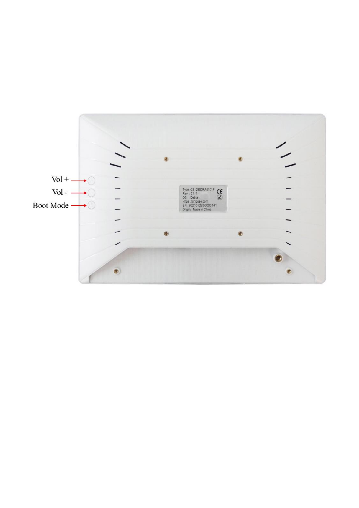
There are 3 buttons on the backside of the case that work as
Audio output Volume+, Volume-, and boot mode selection, as
Figure 7 shows. The product CS12800RA4101A boots from the
internal eMMC by default. If you want it to boot from the USB
OTG connector, please press the Boot Mode button BEFORE power-
on, and release it 3 seconds after power-on.
Figure 7: Buttons
Dimensions
The dimensions of CS12800RA4101A-C111 are
260.54*178.54*26.9mm, as Figure 8~10 show.
The product CS12800RA4101A-C111 can be mounted by using
75*75mm VESA holes.
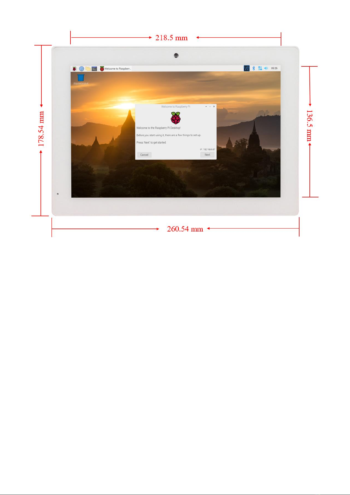
Figure 8: Front Panel Dimension

Figure 9: Backside Dimension
Figure 10: Side Dimension
Mounting
1. Metal stand, as shown in Figure 11, is shipped with the
product:

Figure 11: Stand Mounting
2. VESA mounting is shown in Figure 12. Please note that the
base stand is not included by default.


Figure 12: VESA Mounting
How to Get Support

Please feel free to contact us with any questions, queries or
suggestions.
If your question is about technical support or troubleshooting
for one of our products, we kindly ask you to first check our
documentation for a possible solution.
If you cannot find the solution you are looking for then
details.

Table of contents
Other Mouser Electronics Industrial PC manuals

Popular Industrial PC manuals by other brands


Beckhoff
Beckhoff C5101 Installation and operating instructions

Aversix
Aversix AVB-2000 Series user manual

Beckhoff
Beckhoff C6240-1007 Installation and operating instructions

Bosch
Bosch Rexroth lndraControl VPB 40.1 Project planning manual

spo-comm
spo-comm BOX N2360 quick guide

Neousys Technology
Neousys Technology POC-351VTC user manual