Nobel 160/2 User manual


CONTENTS
GENERAL INFORMATION..................................................................................................................................... 4
DOMESTIC HOT WATER CONSUMPTION ........................................................................................................... 4
SOLAR WATER HEATER OPERATION - WATER HEATING ................................................................................ 4
SOLAR WATER HEATERS APOLLON................................................................................................................... 5
PACKAGING ........................................................................................................................................................... 5
LABELING............................................................................................................................................................... 7
WATER STORAGE TANK SPECIFICATIONS ........................................................................................................ 8
COLLECTOR APOLLON AL SPECIFICATIONS .................................................................................................... 9
APOLLON 160lt/2m2L AYOUT .............................................................................................................................. 11
APOLLON 200lt/2.6m2LAYOUT ........................................................................................................................... 12
APOLLON 320lt/4m2L AYOUT .............................................................................................................................. 13
GENERAL INSTALLATION RULES...................................................................................................................... 14
INSTALLATION POSITION................................................................................................................................... 15
GENERAL PREVENTION MEASURES ............................................................................................................... 16
SUPPORT BASE PARTS...................................................................................................................................... 17
SUPPORT BASE ASSEMBLY FOR FLAT SURFACES........................................................................................ 18
SUPPORT BASE ASSEMBLY FOR INCLINED SURFACES ............................................................................... 21
HYDRAULIC CONNECTION ................................................................................................................................ 24
CLOSED LOOP FILLING ...................................................................................................................................... 24
ELECTRICAL CONNECTION ............................................................................................................................... 25
SYSTEM INSTALLATION ON A TILED ROOF WITH THE WATER STORAGE
TANK UNDER THE ROOF (Natural circulation operation) ................................................................................... 26
CONNECTING THE COIL HEAT EXCHANGER .................................................................................................. 26
POSSIBLE PROBLEMS - SOLUTIONS................................................................................................................ 27
SERVICE - MAINTENANCE ................................................................................................................................. 28
POST INSTALLATION INSTRUCTIONS .............................................................................................................. 29
CHECK LIST ......................................................................................................................................................... 30
3
Solar water heaters - APOLLON
Solar water heaters

GENERAL INFORMATION
In the present manual you will nd all necessary instructions with regard to the installation, operation
andmaintenance of the product.
The company is active in the Solar Energy Field with high-tech equipment, ultra-modern facilities and certied prod-
ucts of high quality. Our experience and know-how support our co operations, before and after sales, both in Europe
and internationally.
Nowadays, the necessity for production and saving of energy without at the same time polluting the environment has
become common knowledge. The planetʼs conventional energy resources are diminishing to a threatening level as
our societyʼs energy requirements are increasing, generating pollutants that affect the climateʼs balance. Renewable
energy sources promise a solution to the energy problem as well as to pollution. Gradually, the international legisla-
tion is changing and encouraging - or even imposing - the use of alternative energy products, with the aim to satisfy
energy requirements without endangering the environment.
DOMESTIC HOT WATER CONSUMPTION
Statistically, it is estimated that the mean family consumption is 35 to 50 liters daily per person. If we add the con-
sumption of a washing machine and a dishwasher, when these are connected to the solar water storage tank, then
each requires 20 liters per day (per wash). Thus, a family of four, for example, with a mean hot water consumption
of 40 liters per person, needs an 160 liters solar water heater. If household appliances connected to the solar water
heater are added, then the demand increases by at least 40 liters daily. In order to take full advantage of the solar
water heater, maximum use of hot water should be made during daytime, so that the system can continuously pro-
duce hot water during the daylight hours, maintaining thus its maximum efciency.
SOLAR WATER HEATER OPERATION - WATER HEATING
The collecting surface absorbs solar energy and heats the liquid (water or antifreeze mixture) that circulates in the
water element. This liquid when heated becomes lighter and is directed to the water storage tank where it heats the
water. The ow of the collector’s liquid is accomplished naturally and not forced (thermosiphonic ow).
The factors that affect the temperature of the water supplied by a solar system are many and their values vary accord-
ing to the season, the time of day and the location. Keeping in mind that the solar system is a system that is exposed
to the weather conditions, basic parameters affecting its performance are the mains water temperature, the available
solar energy and the ambient temperature. The mains water does not have a constant temperature throughout the
year, being much colder in winter compared to summer. Considering 45°C as a v temperature for the domestic hot
water (in order to full the needs of a home) and based on statistic values, in winter the temperature of the mains
water has to be increased by approximately 35°C, whereas during the summer the increase is 20°C.
Similarly, the available solar energy does not remain the same throughout the year, being much less in the winter
months than in the summer months. During periods of reduced sunlight and low ambient temperatures, the solar
water storage tank assures the preheating of the water and is assisted by an electrical heating element or the cen-
tral heating water storage tank (triple action solar water storage tanks). As far as night-time temperature losses are
concerned, these are limited as much as possible by the solar system’s powerful thermal insulation. They are never-
theless affected by ambient temperatures, which vary depending on the location and the weather.
4Solar water heaters - APOLLON

4
2
1
3
SOLAR WATER HEATERS APOLLON
RELIABILITY - HARMONY - AESTHETICS
• High aesthetics and design without obvious piping.
• All the connections between water storage tank and collector are found by the side of the system
The pipes, the cables and the connection elements are covered by special decorative ABS UV PROOF.
APOLLON Solar Systems constitute an ecological proposal and an effective energy solution, combining high
output, autonomy, aesthetics, facility in the installation and money saving. They are made of excellent materials ac-
cording to international specications and have all the certications and tests that conrm their quality.
They are highly aesthetic systems, which can be simply and quickly installed to blend with the traditional or modern
architecture of a building and to provide free hot water almost the whole year round. Even in regions with low sunlight
they achieve the preheating of the water, which contributes to a drastically reduced consumption of conventional
energy.
With the use of solar systems, thermosiphonic or forced circulation, is achieved energy saving of 70-100%. At the
same time the operation time of the boiler or electric resistance is decreased, depending on the sunlight of each re-
gion and the system’s size, with simultaneous reduction of emission of carbon dioxide.
Solar Keymark Certied
PACKAGING
PRODUCT RANGE
APOLLON series thermosiphon systems
are available in the following models:
MODEL
APOLLON 160/2
APOLLON 200/2.6
APOLLON 320/4
DESCRIPTION
160lt tank, 2.0m2collector
200lt tank, 2.6m2collector
320lt tank, 2x2.0m2collectors
1. Boiler
2. Collector(s)
3. Support base, ttings
& Accessories
4. Palette
5
Solar water heaters - APOLLON
Solar water heaters
* The volume of liquid depends on the conguration boiler/collector
* * ½’’ BSP up to 200lt or ¾” for 250lt and above
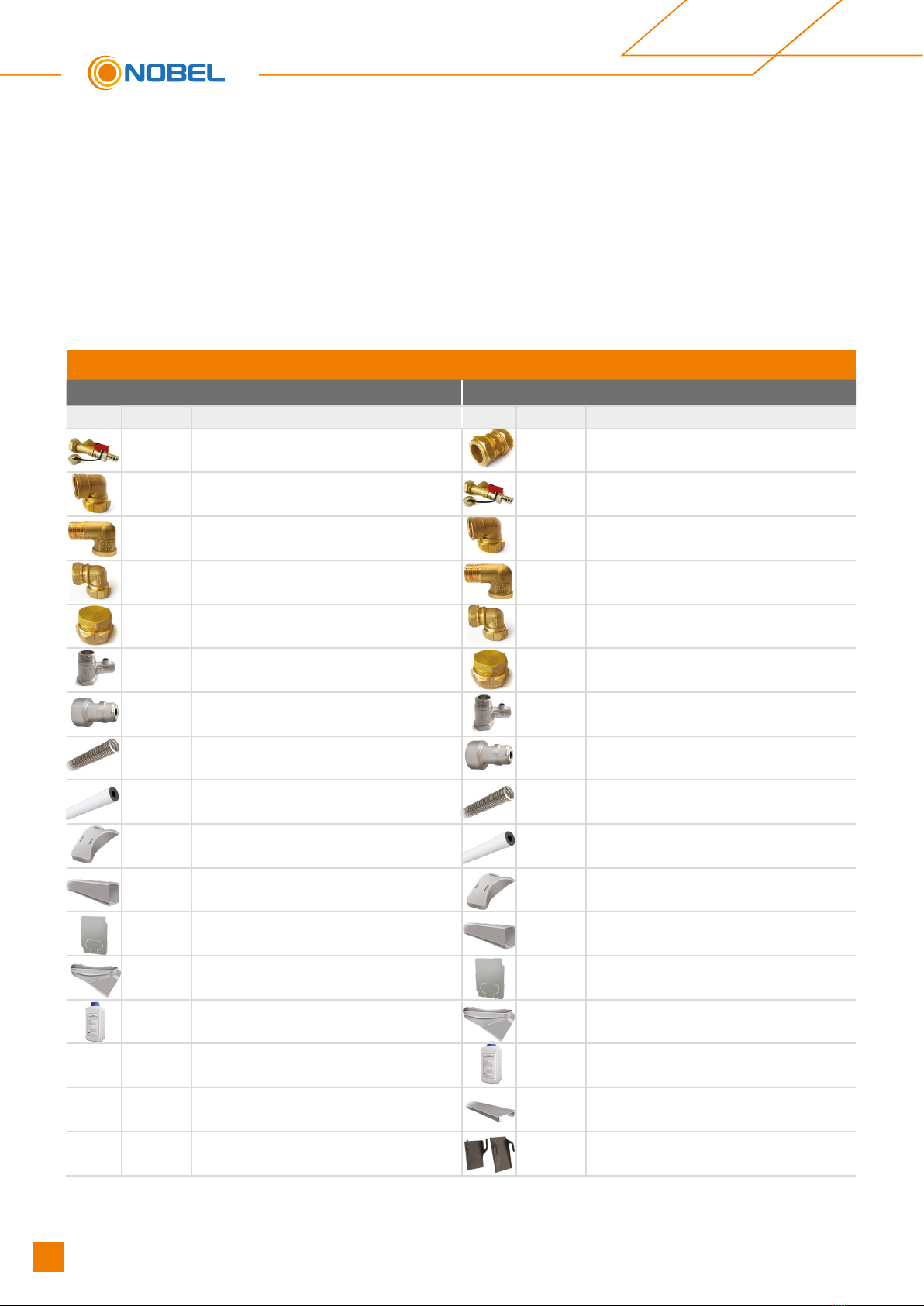
SOLAR WATER HEATERS FITTINGS & ACCESSORIES
Apollon 160/2 & Apollon 200/2.6 Apollon 320/4
Quantity Description Quantity Description
1 PC T-PIECE WITH THE FILLING VALVE 2 PCS CONNECTOR Ø22 COPPER X Ø22 COPPER
1 PC ELBOW ¾’’ FEMALE DN 16 INOX 1 PC T-PIECE WITH THE FILLING VALVE
2 PCS ELBOW ½” FEMALE X ½” MALE 2 PCS ELBOW ¾’’ FEMALE DN 16 INOX
2 PCS ELBOW Ø22 COPPER X DN 16 INOX 2 PCS ELBOW ½” FEMALE X ½” MALE
2 PCS END CAP Ø22 COPPER 2 PCS ELBOW Ø22 COPPER X DN 16 INOX
1 PC ONE WAY SAFETY VALVE 8 bar ** 2 PCS END CAP Ø22 COPPER
1 PC SAFETY VALVE
(1,5 bar for 250lt and above or 2,5 bar up to 200lt) 1 PC ONE WAY SAFETY VALVE 8 bar **
2 PCS INOX TUBE DN 16 1 PC SAFETY VALVE
(1,5 bar for 250lt and above or 2,5 bar up to 200lt)
1 PC INSULATION Ø22 X 9 2 PCS INOX TUBE DN 16
2 PCS BASE COVER 1 PC INSULATION Ø22 X 9
1 SET OF
2 PCS
PIPERWORK COVER
( ALUMINIUM PROFILE) 2 PCS BASE COVER
1 SET OF
2 PCS
PLASTIC COVER CAPS
FOR PIPERWORK COVERS
1 SET OF
2 PCS
PIPERWORK COVER
( ALUMINIUM PROFILE)
1 SET OF
2 PCS PLASTIC PIPE COVERS EXTENSION 1 SET OF
2 PCS
PLASTIC COVER CAPS
FOR PIPERWORK COVERS
* ANTIFREEZE LIQUID 1lt 1 SET of
2 PCS PLASTIC PIPE COVERS EXTENSION
* ANTIFREEZE LIQUID 1lt
1 PC MIDDLE COVER
(ALUMINIUM PROFILE)
1 SET of
2 PCS
MIDDLE COVER SUPPORTS
(ALUMINIUM PROFILE)
Each model packaging contains all the necessary equipment:
1. The water storage tank
2. The collector (s)
3. The support base system & ttings and accessories
The water storage tank is placed between two round styrofoam covers, which are tightened on the storage tank with
stretch lm.
All the parts of the support base system, with the connection ttings, the antifreeze liquid and the other accessories
are packed in a carton box. The ttings and the accessories of each appliance appears in the following table:
6Solar water heaters - APOLLON

LABELING
APOLLON solar water heaters are identied by two stickers, one of them on the tank and the other on the collec-
tor. On these stickers all the details of the system are written. The information provided on the stickers are impor-
tant for the future identication of the system.
· Absorber area: XXX m2
· Aperture area: XXX m2
· Nominal capacity: XXX It
· Design pressure: XXX KPa
· Heat transfer medium:
Propylene glycol / water mixture
· Permissible operating pressure
of the collector heat transfer medium:
XXX KPa
· Electrical Power: XXXX W
· Storage Tank S/N: ?????
· Date of manufacture: ?????
Solar Water Heater
APOLLON XXX/XX
MADE IN EU
Type: Flatplate collector
Dimensions: (L x W x H) (mm): XXXX x XXXX x XX
Overall area (m2): XXX
Absorber area (m2): XXX
Total weight of collector (kg): XXX
Volume of heat transfer uid (lt): XXX
Absorber coating: High selective vacum coating
Standstill temperature: XXX°C
Max. operating pressure: 0.8 MPa (8 bar)
Transparent cover: Tempered, low-iron solar glass
Heat transfer medium: Propylene glycol solution/water mixture
APOLLON AL XXXX
MADE IN EU
Licence No: ΧΧΧ
S/N: ΧΧΧ
Date: ΧΧ/ΧΧΧ
7
Solar water heaters - APOLLON
Solar water heaters
11
17 15172 3 4
6131012
16
98514
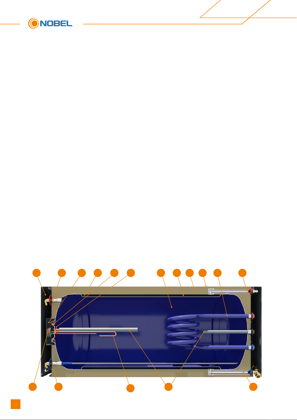
WATER STORAGE TANK SPECIFICATIONS
STEEL - ENAMEL
1. Cylinder: 3mm thickness cold rolled steel with a
double internal layer of enamel, baked at 860°C ac-
cording to DIN 4753. The enameling is done in our
own high tech industrial facilities. The water stor-
age tanks are checked individually upon exit from
the enameling unit, assuring the top quality of the
enamel.
2. Surrounding heat exchanger (Jacket): cold rolled
steel, 1.8mm thickness for the operation of the
closed loop, which is compulsory at low tempera-
tures and also in areas with water with high mineral
content. It is specially designed so as to absorb the
heat transfer medium pressure.
3. Thermal insulation: ecological, high-density, ex-
panded polyurethane ensures minimum heat loss,
maintaining the hot water temperature.
4. External housing: naval aluminium alloy.
5. Cathode protection by magnesium anodes for ef-
fective protection against corrosion and mineral de-
posits caused by electrolytic reactions.
6. Large round ange rubber protected: innovative,
smart design for the quick cleaning of minerals, fast
replacement of anode and immediate access to the
electrical components.
7. Complete sealing of EPDM, non toxic material,
which does not permit water to contact the ange,
thus protecting it against electrolysis and corrosion,
specially made to withstand the generally accepted
specications with regard to the heat resistance.
8. Heating element rated according to the country of
destination local regulations. (Optional, for the use
of electricity as an auxiliary power source). All elec-
trical components carry a CE marking according to
EN 60335-1 and EN60335-2-21 standards.
9. Automatically regulated thermostat with bipolar
protection and auxiliary fuse. All electrical compo-
nents carry a CE marking according to EN 60335-1
and EN60335-2-21 standards.
10. Protective cover: designed to ensure the proper
ventilation of the electrical section and its protection
from the environmental conditions.
Gland: for sealing the passage of the heating ele-
ment’s connection cable.
11. Cold water inlet: brass ½” BSP male threaded pipe
end for water stratication and 8 bar safety valve for
releasing pressure (¾” for 250lt and above).
12. Hot water outlet: ½” BSP male threaded pipe end
(¾” for 250lt and above).
13. Jacket inlet: ¾” BSP male threaded pipe end.
14. Jacket outlet: Closed loop circuit lling point: ¾”
BSP male threaded pipe end.
15. Safety valve connection location 1,5 bar (for
250lt and above) or 2,5 bar (up to 200lt) : ½” BSP
male threaded pipe end
16. External decorative covers made of ABS UV
PROOF cover all joints, eliminating visible piping.
17. Heat exchanger (optional) enameled steel coil with
¾” BSP male threaded ends for use of the heating
produced by central heating systems during the win-
ter the winter (optional)
8Solar water heaters - APOLLON

COLLECTOR APOLLON AL SPECIFICATIONS
1. External one piece aluminium trough of high aesthetics, shaped by deep drawing method in 400 tn capacity
press, made of naval aluminium alloy, rich in magnesium. Robust construction for perfect tightness.
2. High density, eco-friendly thermal insulation achieved with a 60mm thick layer of prepressed rockwool with a
covering of black glass fabric for the minimization of thermal losses.
Rockwool insulation thermal conductivity: λ=0.035 W/m grd (DIN 56612, measured at 0°C)
3. Water frame of copper pipes of suitable gauge and thickness (headers: Ø22, manifolds: Ø8) Headers are
punched with upper expansion, for perfect manifolds tting, thus avoiding pressure drop in the collectors.
(tube pitch) = 93mm (EN 1652).
4. Sun-Selective complete area absorber made of selective aluminium sheet with a special titan coating formed
in vacuum,of high absorbency and low radiation, covers the complete window area as well as the headers, thus
increasing the collector’s absorbency, Laser Welded to the water frame.
5. Special plastic parts for supporting and sealing the water frame to the trough, specially designed for the col-
lector’s ventilation, with sensor supporting option.
Special silicone rubber seals allow uctuation of the absorber’s length (contraction - expansion) in a -40°C
to +200°C temperature range.
6. Tempered solar glass low iron, with a stable coefcient of expansion and high light transmittance, can withstand
adverse weather conditions (e.g. hail storm, extreme temperature changes, etc.).
7. Solar glass rubber seal: UV proofed
8. Aluminium prole electrostatically painted (Al Mg Si 05): for solar glass seating and supporting.
Solar Keymark
Ceritfied
9
Solar water heaters - APOLLON
Solar water heaters

YEARLY ENERGY OUTPUT (kWh/m2)
APOLLON AL 2000, ϑm = 50oC
ATHENS - GREECE 1.493
DAVOS - SWITZERLAND 1.066
STOCKHOLM - SWEDEN 744
WÜRZBURG - GERMANY 801
Normal absorber design with louvers.
Air turbulence increases heat loss
Complete area technology
The uniform area prevents heat loss
FLAT SURFACE INCLINED SURFACE
Supporting base system, made
of electrostatically painted gal-
vanised steel with stainless steel
screws and nuts,
for installation on at or
inclined surfaces
SUPPORT BASE
10 Solar water heaters - APOLLON
NOPart Name DIM (mm) QTY.
1 Beam L (Laminate section 60 x 2.5mm) 2060 x 60 2
2 Beam L (Laminate section 60 x 2.5mm) 2250 x 60 2
3 Beam L (Laminate section 60 x 2.5mm) 1190 x 60 2
4 Beam L (Laminate section 60 x 2.5mm) 925 x 60 2
5 Beam (Laminate section 33 x 2mm) 980 4
6 Boiler Support Ø580 2
7 Collector Support 940 2
8 Protective Cover 420 2
9 Plastic Cover for Supporting Strips (Slab) 2
11 Hexagon Head Bolt M8 M8 x 16 32
12 Hex Nut M8 28
13 Washer Ø8 4
14 Screw 8 x 60 4
15 Upat D10 4
16 Hexagon Head Screw with Washer 4
NOPart Name DIM (mm) QTY.
1 Beam L (Laminate section 60 x 2.5mm) 2060 x 60 2
2 Beam L (Laminate section 60 x 2.5mm) 2250 x 60 2
3 Beam L (Laminate section 60 x 2.5mm) 925 x 60 2
4 Beam L (Laminate section 33 x 2mm) 980 2
5 Beam (Laminate section 33 x 2mm) 980 2
6 Boiler Support Ø580 2
7 Collector Support 940 2
8 Protective Cover 420 2
9 Plastic Cover for Supporting Strips (Slab) 2
11 Hexagon Head Bolt M8 M8 x 16 24
12 Hex Nut M8 20
13 Washer Ø8 4
14 Screw 8 x 60 4
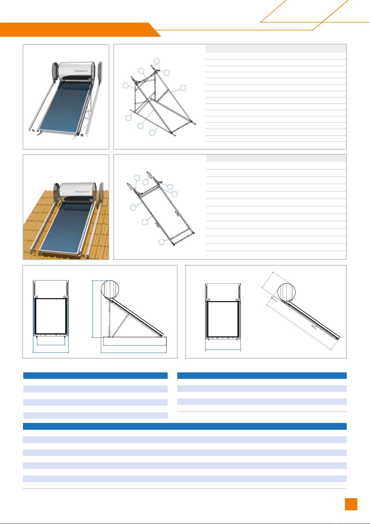
WATER STORAGE TANK 160lt
DIMENSIONS (mm) 580x1150
WEIGHT EMPTY (kg) (without packaging) 66
JACKET CAPACITY (lt) 9
JACKET SURFACE (m2) 0.91
MAX TEST PRESSURE (bar) 12
MAX OPERATING PRESSURE (bar) 8
TOTAL SYSTEM / APOLLON 160lt/2m2
NUMBER OF COLLECTORS 1
SYSTEM WEIGHT EMPTY / FULL (kg) 137 / 302
MAX WATER TANK OPERATING PRESSURE (bar) 8
CLOSED CIRCUIT MAX OPERATING PRESSURE (bar) 2.5
MAX OPERATING TEMPERATURE 95°C
COLLECTOR / APOLLON AL 2000
TOTAL AREA (m²) 2.03
NUMBER OF MANIFOLDS 10
HEAT TRANSFER MEDIUM PROPYLENE GLYCOL SOLUTION
CAPACITY (lt) 1.75
ABSORBER SURFACE (m2) 1.81
TOTAL DIMENSIONS (mm) 2010x1010x110
COLLECTOR TOTAL WEIGHT (without liquid) (kg) 38
ABSORBER SELECTIVE ALUMINIUM
ABSORBENCY / RADIATION COEFFICIENT 95% ±2% / 5% ±2%
4
9
6
7
5
3
2
1
1154
2551
635
900
1856
2034
2121
1154
3
1
2
6
5
9
7
Note: All dimensions measured in mm
FLAT SURFACE
INCLINED SURFACE
FLAT SURFACE INCLINED SURFACE
11
Solar water heaters - APOLLON
Solar water heaters
APOLLON 160lt/2m2LAYOUT

NOPart Name DIM (mm) QTY.
1 Beam L (Laminate section 60 x 2.5mm) 2060 x 60 2
2 Beam L (Laminate section 60 x 2.5mm) 2250 x 60 2
3 Beam L (Laminate section 60 x 2.5mm) 925 x 60 2
4 Beam L (Laminate section 33 x 2mm) 980 2
5 Beam (Laminate section 33 x 2mm) 980 2
6 Boiler Support Ø580 2
7 Collector Support 940 2
8 Protective Cover 420 2
9 Plastic Cover for Supporting Strips (Slab) 2
11 Hexagon Head Bolt M8 M8 x 16 24
12 Hex Nut M8 20
13 Washer Ø8 4
14 Screw 8 x 60 4
NOPart Name DIM (mm) QTY.
1 Beam L (Laminate section 60 x 2.5mm) 2060 x 60 2
2 Beam L (Laminate section 60 x 2.5mm) 2250 x 60 2
3 Beam L (Laminate section 60 x 2.5mm) 1190 x 60 2
4 Beam L (Laminate section 60 x 2.5mm) 925 x 60 2
5 Beam (Laminate section 33 x 2mm) 980 4
6 Boiler Support Ø580 2
7 Collector Support 940 2
8 Protective Cover 420 2
9 Plastic Cover for Supporting Strips (Slab) 2
11 Hexagon Head Bolt M8 M8 x 16 32
12 Hex Nut M8 28
13 Washer Ø8 4
14 Screw 8 x 60 4
15 Upat D 10 4
16 Hexagon Head Screw with Washer 4
WATER STORAGE TANK 200lt
DIMENSIONS (mm) 580x1400
WEIGHT EMPTY (kg) (without packaging) 79
JACKET CAPACITY (lt) 13
JACKET SURFACE (m2) 1.28
MAX TEST PRESSURE (bar) 12
MAX OPERATING PRESSURE (bar) 8
TOTAL SYSTEM / APOLLON 200lt/2.6m2
NUMBER OF COLLECTORS 1
SYSTEM WEIGHT EMPTY / FULL (kg) 158 / 368
MAX WATER TANK OPERATING PRESSURE (bar) 8
CLOSED CIRCUIT MAX OPERATING PRESSURE (bar) 2.5
MAX OPERATING TEMPERATURE 95°C
COLLECTOR / APOLLON AL 2600
TOTAL AREA (m²) 2.53
NUMBER OF MANIFOLDS 13
HEAT TRANSFER MEDIUM PROPYLENE GLYCOL SOLUTION
CAPACITY (lt) 2.12
ABSORBER SURFACE (m2) 2.30
TOTAL DIMENSIONS (mm) 2010x1260x110
COLLECTOR TOTAL WEIGHT (without liquid) (kg) 45.4
ABSORBER SELECTIVE ALUMINIUM
ABSORBENCY / RADIATION COEFFICIENT 95% ±2% / 5% ±2%
4
9
6
7
5
3
2
1
3
1
2
6
5
9
7
1414
2551
635
1414
900 2034
1856
2121
FLAT SURFACE
INCLINED SURFACE
FLAT SURFACE INCLINED SURFACE
12 Solar water heaters - APOLLON
Note: All dimensions measured in mm
APOLLON 200lt/2.6m2LAYOUT
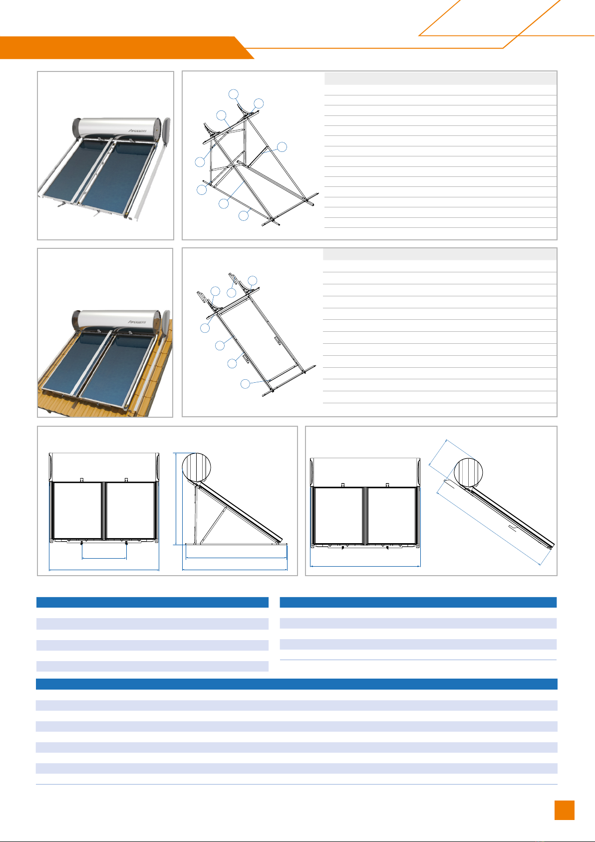
NOPart Name DIM (mm) QTY.
1 Beam L (Laminate section 60 x 2.5mm) 2060 x 60 2
2 Beam L (Laminate section 60 x 2.5mm) 2250 x 60 2
3 Beam L (Laminate section 60 x 2.5mm) 1190 x 60 2
4 Beam L (Laminate section 60 x 2.5mm) 925 x 60 2
5 Beam (Laminate section 33 x 2mm) 980 4
6 Boiler Support Ø580 2
7 Collector Support 1500 2
8 Protective Cover 420 2
9 Plastic Cover for Supporting Strips (Slab) 2
11 Hexagon Head Bolt M8 M8 x 16 St 36
12 Hex Nut M8 28
13 Washer Ø8 8
14 Screw 8 x 60 4
15 Upat D10 4
16 Hexagon Head Screw with Washer 4
NOPart Name DIM (mm) QTY.
1 Beam L (Laminate section 60 x 2.5mm) 2060 x 60 2
2 Beam L (Laminate section 60 x 2.5mm) 2250 x 60 2
3 Beam L (Laminate section 60 x 2.5mm) 925 x 60 2
4 Beam L (Laminate section 33 x 2mm) 980 2
5 Beam (Laminate section 33 x 2mm) 980 2
6 Collector Support 1500 2
7 Boiler Support Ø580 2
8 Protective Cover 420 2
9 Plastic Cover for Supporting Strips (Slab) 2
10 Hexagon Head Bolt M8 M8 x 16 28
11 Hex Nut M8 20
12 Washer Ø8 8
13 Hexagon Head Screw with Washer 4
WATER STORAGE TANK 320lt
DIMENSIONS (mm) 580x2210
WEIGHT EMPTY (kg) (without packaging) 118
JACKET CAPACITY (lt) 19
JACKET SURFACE (m2) 1.79
MAX TEST PRESSURE (bar) 12
MAX OPERATING PRESSURE (bar) 8
TOTAL SYSTEM / APOLLON 320lt/4m2
NUMBER OF COLLECTORS 2
SYSTEM WEIGHT EMPTY / FULL (kg) 231 / 581
MAX WATER TANK OPERATING PRESSURE (bar) 8
CLOSED CIRCUIT MAX OPERATING PRESSURE (bar) 1.5
MAX OPERATING TEMPERATURE 95°C
COLLECTOR / APOLLON AL 2000
TOTAL AREA (m²) 2.03
NUMBER OF MANIFOLDS 10
HEAT TRANSFER MEDIUM PROPYLENE GLYCOL SOLUTION
CAPACITY (lt) 1.75
ABSORBER SURFACE (m2) 1.81
TOTAL DIMENSIONS (mm) 2010x1010x110
COLLECTOR TOTAL WEIGHT (without liquid) (kg) 38
ABSORBER SELECTIVE ALUMINIUM
ABSORBENCY / RADIATION COEFFICIENT 95% ±2% / 5% ±2%
4
9
6
7
5
3
2
1
9
6
7
6
2
1
3
2224
2551
635
900
2224 2121
2034
1856
FLAT SURFACE
INCLINED SURFACE
FLAT SURFACE INCLINED SURFACE
Note: All dimensions measured in mm
13
Solar water heaters - APOLLON
Solar water heaters
APOLLON 320lt/4m2LAYOUT

LATITUDE DISTANCE BETWEEN THE OBSTACLE AND THE COLLECTOR (L)
0° - 25° 1.0 x H
26° - 35° 1.5 x H
36° - 45° 2.0 x H
46° - 50° 2.5 x H
> 50° 3.0 x H
L
H
N
SN
S
Northern Hemisphere Southern Hemisphere
GENERAL INSTALLATION RULES
ATTENTION! Installation must be in compliance with local & national rules concerning water and electrical instal-
lations (plumbing, electricity, hygiene, urban and others).
The solar system’s packaging must be removed at the site of installation in order to protect the device from shocks
during its transportation, making sure that the collectors are not supported on their pipe joints. Until installation is
completed, the collector’s glass must remain covered until the water storage tank is lled with domestic water, so as
to avoid the boiling of the lling liquid or the breaking of the glass. The plastic protective caps must be removed from
the water storage tank’s and the collector’s pipe joints.
Installation location - shading: Prior to installation, a proper selection of the location must be made by the install-
er (in agreement with the customer), and the surface must be checked (taking into consideration its static resist-
ance), so that it can bear the weight of the system.
On inclined roofs the system should not be placed between two beams but above a single one.
The position chosen for the solar water heater installation should not be shaded by any obstacles such as trees,
buildings and other all year round, so as to ensure at least 4 hours of uninhibited exposure of the collector to the
sun during the midday hours.
Any deviation means a reduction in the system’s performance. If a deviation from the proper orientation cannot be
avoided, then the system’s performance should be corrected by increasing the collector surface, following a study
and evaluation of the specic conditions that apply. As the sun ray’s angle of attack varies with time but also depend-
ing on the system’s location, the collector’s angle should be approximately equal to the installation location’s latitude.
At this angle the maximum energy gain on an annual basis is achieved.
Installation particularities: In case there is no compatibility between the surface where the solar water heater will be
installed (inclined or at) and the standard equipment provided with the system, a different kind of equipment should
be used. The responsibility for the equipment chosen lies on the installer and in no case on the company. It is up to
the installer to propose & install the different equipment required, who must previously agree it with the customer.
Special weather conditions: In regions suffering from heavy snowfalls, please make sure that the snow is always
timely removed. For this case and cases of regions with storms, high wind velocity, rainfall, cyclones, tornadoes, the
system must be placed on the roof as rmly as possible and must be tightened with extra metal stripes. In areas
where these conditions occur and hail of more than 20mm in diameter is to be observed, it is recommended that
insurance for the solar water heater is issued. In every case, it is recommended to secure your solar water heater on
the support base system with more metal belts than those provided.
Orientation - optimum angle: a basic factor for the system’s optimum
performance is the selection of its angle and orientation for its particular
location and the time during which the maximum gain is required.
The solar system should be positioned so that the collector’s surface
faces the geographical south, if the installation takes place in the North-
ern Hemisphere (and the geographical north for the Southern Hemi-
sphere), i.e. it should always face the Equator.
14 Solar water heaters - APOLLON
APOLLON AL COLLECTORS
INSTALLATION MODE WIND LOAD
[km/h] / [kN/m2]
SNOW LOAD
[kN/m2]
Inclined surface 151 / 1.5 2.17
Flat surface 151 / 1.5 2.17
Piping: the routing of the piping and cabling must be agreed upon between the installer and the client, so as to ensure
the proper installation of the solar system in compliance with local rules concerning water and electrical installations.
Make sure that the tubes connecting the storage tank with the collector and the piping to/from the water heater are
insulated in such a way that they can withstand temperatures covering the range of: -30°C to 120°C. Anti-UV protec-
tion must be used for the insulation.
Antifreeze Liquid: The special heat transfer medium used in the closed circuit protects the system from freezing
and from salt accumulation inside the collector tubes. The jacket in which the heat transfer medium’s circulation
takes place, does not communicate with the water tank. The thermal uid must be well mixed with water in a per-
centage that is necessary to protect the system. The responsibility for the appropriate heat transfer medium quanti-
ty as well as for the use of other liquid than the one accompanying the solar water heater lies on the installer and in
no case on the company.
The use of water or inappropriate liquid may annul the warranty validity.
After the installation is completed, the area where the work was executed should be clean & tidy. The warranty
should be lled in and the customer should sign it and immediately mail it to the company. The customer should ll
in the check list provided by the company. The company does not hold any responsibility that may be the result of
an inappropriate installation or incorrect use of components used for the solar water heater installation.
INSTALLATION POSITION
The installation is only allowed on roofs and at surfaces of adequate bearing capacity. Before you proceed with the
installation, make sure that the roof and/or the construction is of adequate bearing capacity in terms of statics, always
according to the expected maximum loads at the installation point. If the installation is in a place with an extremely
big wind and snow load, the system as a whole should be statically checked by a skilled person, e.g a specialized
engineer. In special cases, strengthening or more solid constructions may be required.
Space requirements for installation on the roof (TILED ROOF)
For the installation on the roof the following points must be taken care of:
• The minimum distances from the ends of the roof should be:
- From the sides: distance equal to the width of two tiles
- From the top of the roof: distance equal to three rows of tiles
• The minimum distance limit of 0.8 m should necessarily be respected, in order for the collectors and the mounting
accessories not to be exposed to winds the power of which increases on the perimetrical edges of the roof.
Space requirements for free standing installation (FLAT ROOF)
The system should be installed at least 1.5 m away from the edges of the roof so as for:
• The systems to be accessible for maintenance reasons.
• The systems and the xing system not to be exposed to strong winds which are developed at the ends and edges
of the roof.
• The snow to be removed.
For the proper operation of the system, the minimum recommended inclination angle of the collectors is 20°
15
Solar water heaters - APOLLON
Solar water heaters
The rates listed in the above table relate to the resistance of the collector that has been tested on an inclined surface with an angle support of
15°-75° and on a at surface with an angle support of 35°. Τhe system may only be installed in locations with lower wind and snow load values
than the ones mentioned above.

GENERAL PREVENTION MEASURES
• Please respect the instructions related to accidents prevention and the safety rules during the installation of the
solar thermal systems as well as the piping.
• Please keep the work place clear and free of objects obstructing the execution of works.
• Do not let children, pets and other people to come in contact with the tools or close to the working place. This has
to be respected, especially in case of existing buildings renovation.
• Store the antifreeze liquid in a safe place away from children.
• During the execution of maintenance, service or installation modication works, please remove the electrical de-
vices and tools current collector or protect the electrical devices and electrical tools against unintended activation.
• Use only the tools intended to be used for this specic solar system. The use of other components or inappropri-
ate tools can cause accidents.
Requirements related to the personnel
• The installation of our Solar Thermal systems can only be undertaken by authorized specialized companies and
trained personnel.
• Works in electrical installations or conductors have to be executed by trained & specialized electro technicians
only.
Labour uniforms
• Have protection glasses on, as well as appropriate work uniform, protection shoes, protection helmet and special
long hair net.
• Do not wear baggy clothes or jewelry, as they me be trapped in movable parts.
• If, despite the use of protection glasses, antifreeze liquid comes in contact with your eyes, wash off your eyes with
plenty of water and with the eyes wide open.
• Please wear protection helmet during the installation works executed at the level of or above the head.
Installation of the water storage tank
• For the transportation, mounting & installation of the tank use forklifts suitable for the dimension and weight of the
tank.
• Please protect the enameling surface from beatings during transportation and installation.
• Due to the tank’s weight, there is a risk of accidents. Please make sure that the bearing capacity of the ground
where the tank is going to be installed is adequate, when the tank is full.
LIGHTNING PROTECTION
The metal construction conforms to the general requirements of the ELOT 1197 Standard and the special lightning
protection requirements of the ELOT 1412 Standard which takes into account the environmental conditions as well
as the altitude.
16 Solar water heaters - APOLLON

1
2
3
4
6
5
0
13
173
213
308
1752
1847
1887
2047
2060
0
134
204
944
2168
2208
2238
2250
279
86
0
11.5
38.5
342.5
847.5
1151.5
1178.5
1190
0
10
110
815
915
925
0
15
55
490
925
965
980
10
0
10
110
815
915
925
0
11,5
38,5
342,5
847,5
1151,5
1178,5
1190
0
13
173
213
308
1752
1847
1887
2047
2060
1
2
3
4
6
5
0
15
55
490
925
965
980
7 8
5
0
134
204
944
2168
2208
2238
2250
279
86
SUPPORT BASE PARTS
For 4m2collector surface
For 2m2 & 2.6m2collector surface
NOTE: For 2m2& 2.6m2 collector surface systems, part 5 is substituted by the following:
17
Solar water heaters - APOLLON
Solar water heaters
18 Solar water heaters - APOLLON
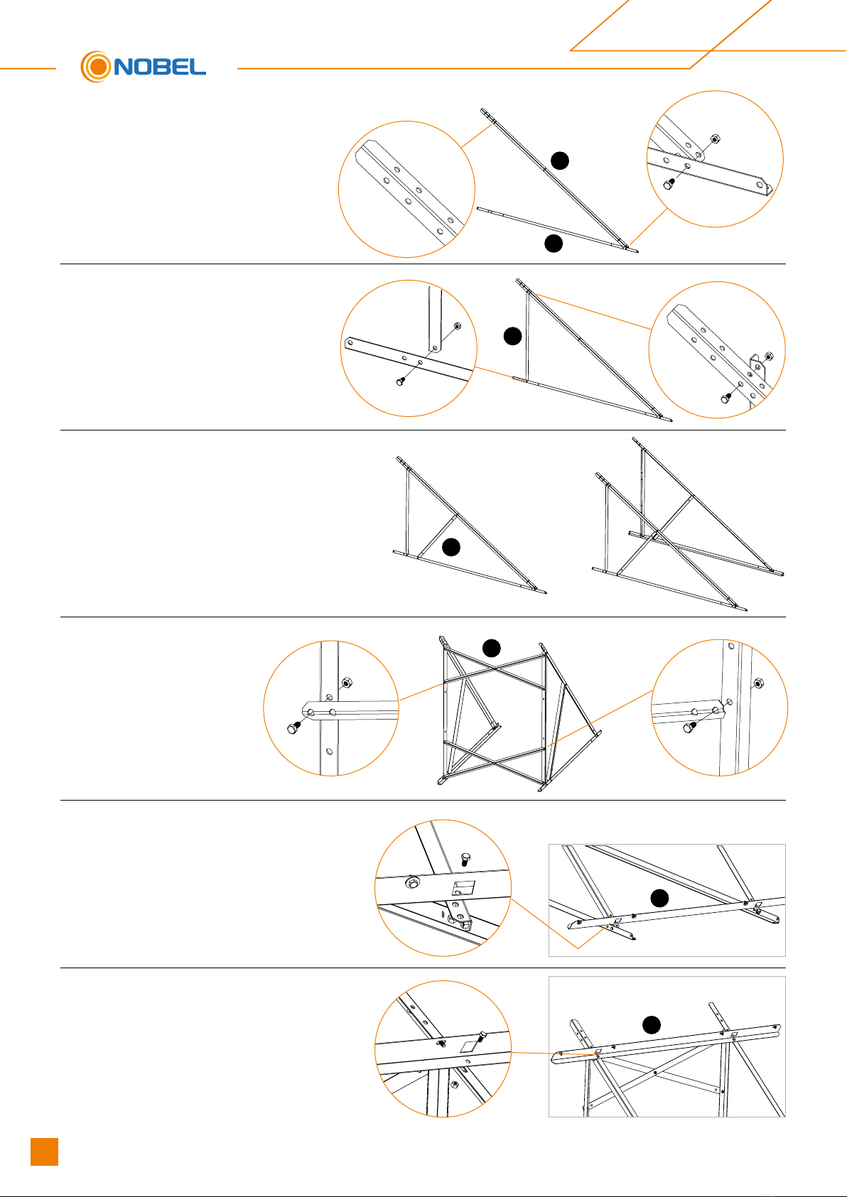
SUPPORT BASE ASSEMBLY
ON A FLAT SURFACE
5. In case of two collectors model,
place the collector supporting part
5on bottom part of the frame and
tighten all screws.
6. Repeat for the upper part
5
5
1. Screw parts 1to part 2,
using the M8 screws and nuts
included in the packaging.
2
1
2. Place the vertical part 3to the
above parts
3
3. Screw part 4to the rest parts of the
frame and tighten all screws.
Repeat steps 1, 2 & 3 for the other
pairs of parts.
4
4. Place parts 6cross-
wise and tighten the
screws.
6
19
Solar water heaters - APOLLON
Solar water heaters
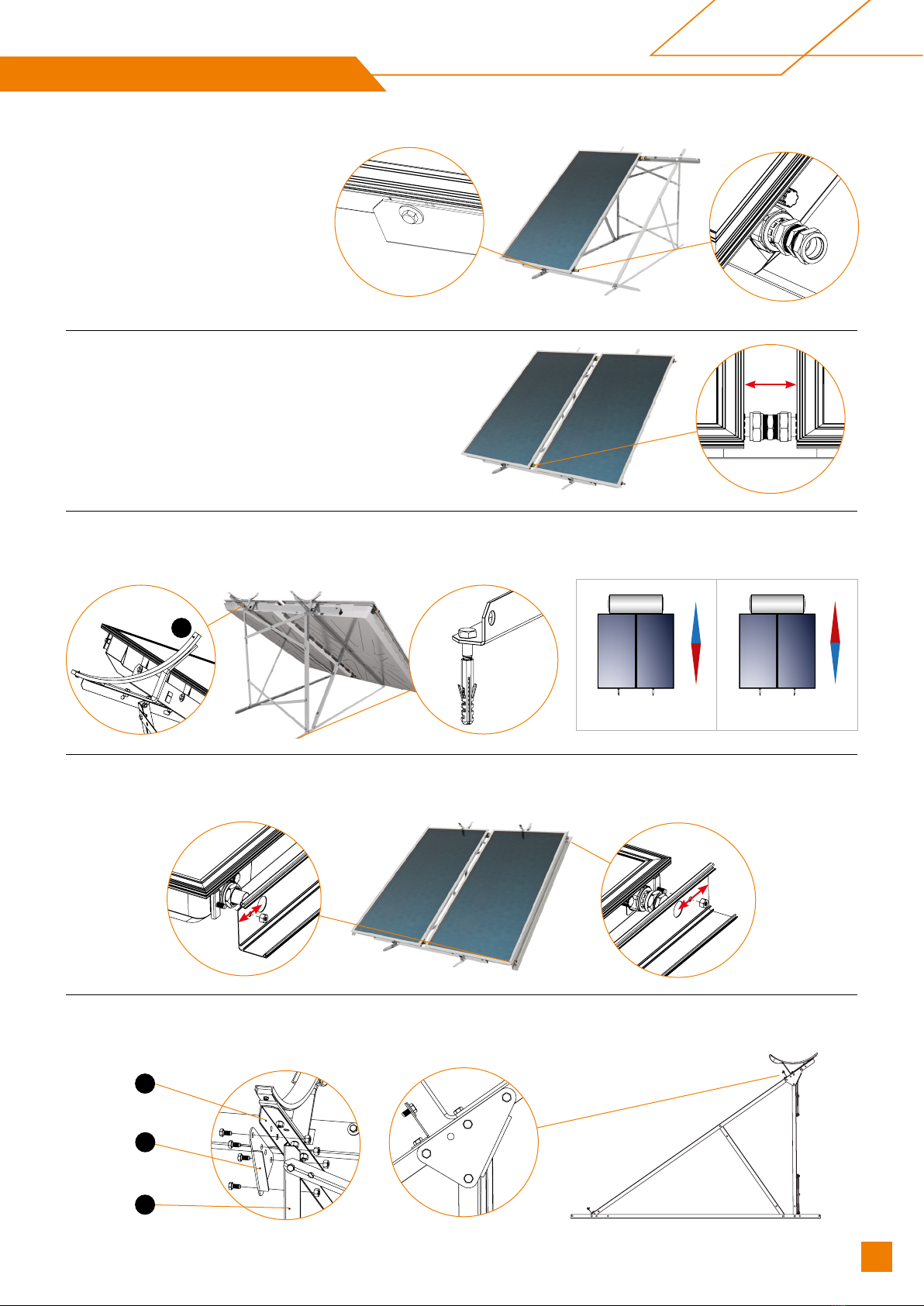
7. In case of two collectors,
rst place the left one to the
bottom part 5lifting the upper
part 5. Place the screws with
the support washers of the
collector (4 for each collector)
without tightening them.
Place the Ø22 mechanically
tightened unions at the edges
of the collector.
8. Join the second collector and
tighten the unions*.
10. Place the decorative covers at the external collector’s sides adjusting the channel’s aperture at the collector’s
socket. Screw the channels at the special collector’s metal piece using the screws and the corresponding nuts.
9. Screw on the two supports 7of the tank. Tighten all screws on the base. Properly orientate the base with the
collector. Firmly attach the base using 4 Upat D10 and bolts (M8x60).
N
SN
S
Northern Hemisphere Southern Hemisphere
60mm
7
70mm
90mm
2
10
11. In case of 250lt boiler and above screw reinforcing plate (10) to collector beam(2) and vertical beam(3) with
bolts M8x16 and nuts. Repeat for another side.
3

20 Solar water heaters - APOLLON
STEP 23
STEP 15
STEP 16
STEP 17
STEP 21
STEP 12
STEP 17
STEP 19
STEP 14
*
12. Place and tighten the Ø22 mechanically tightened plug on the top right and on the bottom left of the collector/ col-
lectors*. Place the water storage tank on the base with its electrical components to the left, when viewing the water
storage tank from the front.
13. Centre the water storage tank’s position on the collector/s. Rotate the water storage tank (if necessary) in order for the
cold and hot domestic water sockets to remain vertical to the horizontal surface. Screw the water storage tank onto
the base using the screws provided in the packaging. Ensure the appliance is not tilted and is properly levelled. It is
necessary to use a level.
14. Place the small exible tube on the special connection 3/4”xDN16 INOX* at the water storage tank’s side where the
heating element is located and to the socket marked “collector intake”.
15. Join the other end to the top left socket of the collector using the Ø22 x DN16 INOX corner tting, having rstly pass
the tube through the plastic channel extension.
Note: Through the above extension, pass the cold and hot domestic water sockets during the hydraulic connection.
16. Place the Τ- piece with the lling valve to the socket on the right side of the water storage tank marked “collector
return”.
17. Place the big exible tube with the special connection to the Τ- piece on the right side of the water storage tank.
18. Place the other end at the bottom right socket of the collector using the Ø22 x DN16 INOX corner tting*, having rstly
passed the tube through the insulation tube. Tighten all unions in the system as well as all the screws on the base.
Do the hydraulic connection, ll the closed loop and do the electrical connection as described in the relevant sections.
Check for leaks.
19. Fit all pipe covers and faWsten with the plugs on the bottom part.
20. Place the middle cover at the upper socket. After having placed the collectors at a parallel to each other position,
fasten them to the bottom side .
21. Fit the water storage tank supporting base covers.
22. Fit the plastic channel extension at the pipework cover. Check that the water storage tank is completely centred with
the plastic channel extensions.
23. Align the water storage tank external ap with the sockets and press to fasten, making sure that the top of the plas-
tic channel extension perfectly ts at the water storage tank’s cover aperture. Repeat the step for the second ap.
* Use two wrench keys in order to avoid the copper tube mechanical strain.
STEP 20
This manual suits for next models
2
Table of contents


