NoiseKen EPS-02Sv2 User manual

INSTRUCTION MANUAL
Sound Source Visualization System
MODEL
EPS-02Sv2
NOISE LABORATORY CO., LTD.
Edition 2.00
AEA00085-00E-1

Disclaimers
•The content of this manual is subject to change without prior notice.
•The reproduction or transfer of this manual in any form whatsoever is prohibited without the prior written
permission of the Noise Laboratory Co., Ltd. (NoiseKen).
•Although every effort has been made to ensure that the content of this manual is accurate and complete,
please contact NoiseKen if you find any unclear points, errors, omissions, or other inconsistencies.
•NoiseKen will not be liable for any damages that occur due to improper usage of this product by the
customer, failure to follow the information in this manual, or repair or modifications performed by a third
party other than NoiseKen or a party designated by NoiseKen.
•Regardless of the above, NoiseKen will not be liable for any test results obtained using this product or for its
effects on the tested equipment.
•The trademarks and company names appearing in this manual are trademarks or registered trademarks of
their respective companies. In this manual, the trademark symbol (TM) and registered symbol (R) are
omitted.
•Security Export Control System: Requirements for Exporting This NoiseKen Product
Although this product does not come under rows 1 to 15 of Appended Table 1 of the Export Trade Control
Order, it comes under the restricted goods catch-all in row 16. For this reason, you must submit an export
declaration to NoiseKen before exporting this product outside Japan or temporarily taking it outside Japan
to enable us to conduct a confirmation screening of the final customer, final application, and other details. In
the provided information, the customer will be requested to confirm that the final destination country, final
customer, final application, and other details in the export declaration comply with the restrictions in row 16
of Appended Table 1 of the Export Trade Control Order.
To ensure strict compliance with export control laws, submission of an export declaration is required. Also,
when reselling the product at a location inside or outside Japan, the repurchaser must also be notified of
above information.
* Because the above information is based on laws and regulations, it is subject to change due to revisions in the
applicable laws and regulations. For details on the control and export procedures in laws and regulations, please
contact the applicable government agency (such as the Ministry of Economy, Trade and Industry; Trade and
Economic Cooperation Bureau; Trade Control Department; Security Export Control olicy Division).

1
1. Software Licensing Terms
1. Usage Limitations
Please use the Software for the purposes described in the instruction manuals or the
specifications. Do not use the Software for purposes other than these.
2. Intended Users
Please ensure that individuals who use the Software have received the appropriate training and
practice with regard to the entire system in which the Software runs, including the usage
environment, equipment safety, and operating methods.
3. Ability to Make Copies
The Software may be installed and used on multiple personal computers by individuals who are
members of the business location (factory, branch office, business office, etc.) that purchased the
Software.
4. Handling of Intellectual Property Rights
The Software and the intellectual property rights including copyrights for the Software belong to
NoiseKen.
5. Usage Period
The usage period designated by NoiseKen shall take effect when the installation of the Software
or the prescribed procedure for use, whichever is later, has been completed by the Customer, and
the Customer's right to use the Software shall be deemed to have expired at the end of this usage
period.
6. Usage Termination Conditions
If the Customer has violated any of the provisions in this document, or has infringed on the
copyrights or other intellectual property rights of NoiseKen, NoiseKen shall have the ability to
revoke the Customer's license to use the Software.
7. Procedures Upon Usage Termination
The Customer shall promptly uninstall the Software. (If other instructions have been issued by
NoiseKen, these shall be followed by the Customer.)
8. Disclaimer
NoiseKen and its dealers and affiliates will not be liable for any customer damages arising from the
use of this software or for claims of damages by third parties against customers except in the case
of intentional or gross negligence by NoiseKen, its dealer, or affiliates.
9. Prohibitions
The following actions are prohibited with regard to the Software.
(1) Modifications, additions, and other alterations to the functionality of the Software
(2) Any form of reverse engineering, including decompilation and disassembly, of the Software
(3) Reselling, transferring, redistributing, licensing, etc. of the Software, or the accessories
provided by NoiseKen for the Software, to third parties
(4) Storing the Software, or the information, documentation, and the like provided by NoiseKen for
the Software, on a network in a state wherein it may be conveyed to a third party
10. Handling of USB and other protection keys
The software provided by NoiseKen may require USB or other protection keys.
(1) If a protection key is included in the accessories, the protection key must be mounted in the
computer where the software is used.
(2) As a general rule, the protection key is not reissued. In the event that the protection key is
damaged or lost, please contact the NoiseKen Sales (or Repair) Division.

2
2. IMPORTANT SAFETY PRECAUTIONS
This software performs visualization of sound pressure in space. Important information for safe
operation when performing visualization using this software is provided below, and so be sure to read
it carefully before use.
Also, be sure to carefully read this manual and the instruction manual for each device to be used
before using this software.
1. Incorrect or careless operation could result in a fatal injury.
2. Avoid use in locations exposed to high humidity and large amounts of dust.
3. When making connections, electric shock can occur due to contact with the supply
voltage, and so before performing any connection work, be sure to turn off the power
to the each device, and check that no power is flowing.
4. Do not turn off the power to the each device or disconnect any cables while this
software is running. This could cause PC operation to become unstable or the OS to
malfunction. Be sure to always exit this software before turning off the power to the
each device.
5. If the coaxial cable is bent too hard, there is a possibility of breaking the wire. Handle
the coaxial cable with care.

3
3. Item Check List
Before starting use, check that the parts and accessories below are
included with the product.
A
B
C
D
E
F
G
H
I
J
K
L
M
A: Sound pressure sensor (Microphone)
・Main part································································ 1
・Sensor cover (yellow/red/blue) ··································· each 1
・Data sheet······························································ 1
B: Microphone power supply
・Main part································································ 1
・AC adapter····························································· 1
・Manual ·································································· 1 set
・Battery··································································· 2
C: Web camera
・Main part································································ 1
・Warranty································································ 1
D: USB protect key ····························································· 1
E: BNC coaxial cable (3 m) ·················································· 1
F: BNC-N coaxial cable (1.5 m) ············································· 1
G: LAN cable (2 m)····························································· 1
H: USB extension cable (2 m) ··············································· 1
I: Camera tripod
・Main part································································ 1
・Storage bag···························································· 1
・Manual ·································································· 1
J: Installation DVD (E S-02Sv2) ··········································· 1
K: Japanese Quick Start Guide ············································· 1
L: English Quick Start Guide················································· 1
M: Storage case································································· 1
* The key of C, J, K and L are included in the upgrade version.
* The key of D, J, K and L are included in the secondary license version.
* The warranty for A, D, E, F, J and M is in accordance with our warranty policy.

4
4. Introduction
Thank you for purchasing the EPS-02Sv2 Sound Source Visualization System. Before
using the EPS-02Sv2, be sure to carefully read this manual to ensure that you maximize
its performance when operating the EPS-02Sv2.
This User Guide is provided to ensure that people who follow the operating procedures
and safety information can safely use the EPS-02Sv2 and maximize its performance.
Place this User Guide in a location where it is easily accessible whenever operating the
EPS-02Sv2.
4-1. Features
Enabling visualization of sound pressure in space
A sound pressure sensor is used to perform frequency analysis with a spectrum analyzer and
to map to the emission location of the actual image.
The emission location is mapped relative to the sensor location recognized using the web
camera.
An area of up to 64 blocks × 48 blocks can be measured.
A superimposed image of the measurement strength distribution diagram and web camera
image are displayed for enabling easy identification of the emission source. The density of
the strength distribution and frequency range can be specified.
Measured results can be saved to a file, and the content of the measurement results and file
can be compared for enabling visualization of the effects of corrective actions.
Because the measurement sensor can be moved not by a device like a positioner but by
hand, easy measurement is possible even in cramped spaces, outdoors, and other
difficult-to-access locations.

5
5. Contents
1.
SOFTWARE LICENSING TERMS .............................................................................1
2.
IMPORTANT SAFETY PRECAUTIONS..................................................................... 2
3.
ITEM CHECK LIST.....................................................................................................3
4.
INTRODUCTION ........................................................................................................4
4-1.Features ····················································································································· 4
5.
CONTENTS................................................................................................................ 5
6.
OVERVIEW ................................................................................................................ 7
6-1.Notation Used in This Guide···························································································· 7
6-2.EPS-02Sv2 Features ····································································································· 7
6-3.Measurement Principle··································································································· 8
7.
SYSTEM CONFIGURATION DIAGRAM.................................................................... 9
7-1.System Configuration Diagram························································································· 9
7-2.Functions of Each Device ······························································································10
8.
PREPARATION ........................................................................................................ 11
8-1.System Backup ···········································································································11
8-2.System Connections·····································································································11
9.
OPERATION PROCEDURE..................................................................................... 12
9-1.Starting and Exiting the Software·····················································································12
Starting the Software .............................................................................................................................12
Exiting the Software...............................................................................................................................12
9-2.Image Recognition Settings····························································································13
Image Recognition Setting Dialog Box..................................................................................................13
Device Name .........................................................................................................................................13
Device Filters .........................................................................................................................................14
Other Settings........................................................................................................................................15
Image Recognition Setting ....................................................................................................................16
9-3.Communication Settings································································································17
Communication Settings Dialog Box .....................................................................................................17
Equipment Name ...................................................................................................................................17
Interface.................................................................................................................................................18
9-4.New Measurement (Setting Measurement Conditions) ·························································18
View Window .........................................................................................................................................18
Condition Tab ........................................................................................................................................19

5.Contents
6
Image Division Size............................................................................................................................... 20
Capturing............................................................................................................................................... 20
Measurement Time Setting................................................................................................................... 21
Frequency ............................................................................................................................................. 22
Spectrum Analyzer................................................................................................................................ 22
Microphone Sensitivity .......................................................................................................................... 23
GAIN...................................................................................................................................................... 23
9-5.New Measurement (Performing Measurement) ·································································· 24
Performing Measurement...................................................................................................................... 24
Deleting Measurement Data ................................................................................................................. 25
Recapturing Camera Image.................................................................................................................. 26
9-6.Measurement Data Analysis··························································································· 27
Measurement Data................................................................................................................................ 27
Auto Distribution.................................................................................................................................... 28
Interpolation .......................................................................................................................................... 29
Transmittance ....................................................................................................................................... 29
Frequency Range.................................................................................................................................. 30
Measurement Information ..................................................................................................................... 31
Memo .................................................................................................................................................... 31
Matching Map View Data ...................................................................................................................... 32
Exporting Measurement Data ............................................................................................................... 33
10.
SETUP................................................................................................................. 34
10-1.Important Notes on Setup ···························································································· 34
10-2.Network Address Settings···························································································· 34
10-3.Installing the Software································································································· 35
11.
SPECIFICATIONS............................................................................................... 36
11-1.Specifications············································································································ 36
11-2.System Requirements································································································· 36
11-3.Supported Spectrum Analyzers····················································································· 36
12.
WARRANTY........................................................................................................ 37
13.
NOISE LABORATORY SUPPORT NETWORK .................................................. 40

7
6. Overview
6-1. Notation Used in This Guide
The marks used in this guide and their meanings are provided below.
Provides an additional explanation.
Indicates a location for further reference.
Indicates a setting restriction.
Indicates that you must check before usage.
6-2. EPS-02Sv2 Features
*Measurement sensor is detected from the image for recognizing the measurement
location
The measurement object and measurement sensor are captured by a camera, and the
measurement sensor is found within the image for identifying the measurement location. The
recognized measurement location is a relative location within the camera image.
Any user-selected color can be specified for the measurement sensor. However, selecting a
color with the same tone as the background color will result in a reduced rate of recognition
and even mistaken recognition in certain cases.
The measurable range is the area shown in the camera, but it is restricted to a range that can
be recognized by the measurement sensor.
*Automatic control by software
Measurement sensor recognition from the camera image and control of the spectrum
analyzer are performed automatically. The measurement results can be output as a CSV file,
and the image can be output in BMP format.
Also, because the software is a Microsoft Windows application, it provides an
easily-accessible interface that uses mouse operations while viewing the screen.
*Visual display of measurement results
The measurement strength distribution and camera image are displayed as a superimposed
image on the computer screen. Also, the mouse pointer in the image can be used to confirm
measurement results for any selected position.
In addition, an interpolation view of the surrounding strength can be used to provide easier
assessment of the generation points.
*Full emission analysis function for measurement points
Data can be collected for the entire measurement frequency range generated from the
measured object in a single measurement. The emission map for each frequency band is
also redisplayed by simply specifying the frequency band.

6.Overview
8
6-3. Measurement Principle
The EPS-02Sv2 system performs two main operations for enabling visualization of the sound. First,
it performs image recognition that identifies the measurement sensor location from the recording
image. Second, it provides a color-coded distribution on the image indicating the strength of the
signals detected by the measurement sensor.
In image recognition, 640 x 480 pixel video from the camera is monitored in real time, and a
specific color only is extracted based on the specified parameters for "hue", "brightness", and
"saturation". By finding the focal point of the area with the specific color, the location of the specific
object (measurement sensor) can be found in the image.
If an object with the same color as the specified color, but that is not the measurement sensor,
appears in the image, the measurement sensor location cannot be recognized correctly because the
focal point of all objects of this color is calculated. Therefore, the parameter settings for "hue",
"brightness", and "saturation" that are used to detect the measurement sensor, the brightness and
light exposure in the recording location, and selection of the lighting are important factors. Also, the
cover of the measurement sensor must be adjusted based on the color of the measurement object.
A spectrum analyzer is used as the measuring instrument for enabling measurement of the sound
pressure level. The spectrum import count and frequency range vary depending on the measurement
sensor and measuring instrument. The measurement data is mapped to a position specified by image
recognition. The method of capturing data at the same position can be selected from MAX HOLD,
PEAK HOLD, FREE RUN, and SINGLE.
After measurement is completed, the frequency range that you want to view can be selected for
creating a strength distribution combined with the image.

9
7. System Configuration Diagram
7-1. System Configuration Diagram
①Control C
This controls the various devices and conducts sound pressure measurement.
②Web camera
This captures the image of measurement object.
③Sound pressure sensor
Measures sound pressure and outputs analog signals. This sensor is powered via the IN UT
terminal of the microphone power supply. A certain color must be added to the sensor so that the
C can recognize the sensor position. Attach an included sensor cover to the sensor before use.
④Microphone power supply
Connect the sound pressure sensor to “IN UT CH1” using the included BNC cable, and connect
a spectrum analyzer to “OUT UT CH1” using the included BNC-N cable.
Make sure that IN UT and OUT UT connections are correct.
Be sure to take into account wrong connections may damage the equipment.
Set the GAIN changeover switch to 0 dB (default). If the switch is set to 20 dB, make sure that the
setting does not exceed the maximum input of the spectrum analyzer
⑤Spectrum analyzer
The spectrum analyzer is connected to the C using the supplied LAN cable.
Support is provided for some spectrum analyzers described in [11-3.Supported Spectrum
Analyzers] on page 36. lease consult with NoiseKen for use of spectrum analyzers that are not
supported.
USB cable
LAN cable
①
BNC( )-N( )
coaxial cable
③
BNC( )-BNC( )
coaxial cable
④
②
⑤

7.System Configuration Diagram
10
7-2. Functions of Each Device
①Control PC
This enables running of system control software. This software imports images from the web
camera, identifies the measurement sensor within the image, and finds its location. After
frequency analysis is performed by the spectrum analyzer, the control PC receives the
measurement results and maps them to that location.
②Web camera
This is a general-purpose web camera. The image of measurement object is captured and
transferred to the PC. The web camera is connected to the PC by a USB cable. If necessary, the
connection can be extended by a USB extension cable.
③Sound pressure sensor
This has a built-in microphone to measure sound pressure.
A special cover is attached to the sensor before use to improve the recognition rate.
The cover is made of windshield sponge, which reduces wind noise.
④Microphone power supply
This supplies power to the sound pressure sensor connected to the INPUT terminal and outputs
analog signal from the OUTPUT terminal.
By using the GAIN changeover switch above the OUTPUT terminal, signals are amplified to 20
dB. For the EPS-02Sv2, the switch must be set to 0 dB (default).
Since the spectrum analyzer is highly sensitive, amplified signals are usually not needed.
If the switch is set to 20 dB, before use, make sure that the setting does not exceed the maximum
input of the spectrum analyzer.
It is powered by the AC adapter or batteries.
・Switch [ON]: Supplies power to the sound pressure sensor connected to the INPUT terminal
and outputs signals from the OUTPUT terminal.The BATT LED is not lit, which is the normal
status.
・Switch [OFF]: Stops supplying power to the sound pressure sensor and outputting signals from
the OUTPUT terminal.
・Switch [BATT]: Checks whether the voltage of the AC adapter or the batteries are normal. If it is
normal, the BATT LED is lit.
⑤Spectrum analyzer
This performs frequency analysis of the signals from the measurement sensor and sends the
spectrum data to the PC.

11
8. Preparation
CAUTION
In environments exposed to extremely large amounts of external noise, the equipment may be unable
to realize its maximum performance.
Even when indoors, the equipment can be affected by an air conditioner and other electronic devices.
During measurement, try to minimize external noise. Depending on the PC, its cooling fan may
generate large noise not suitable for measurement.
8-1. System Backup
NoiseKen provides an optional service (additional charges apply) for installing the EPS-02Sv2
program in your PC before providing the program, but if the program is erased, install it from the
supplied DVD. Copy the content of the DVD to a hard disk, removable disk, or other location and
store it there in case of loss.
The CD included with the web camera mounted on the PC is provided to the customer, but it is also
recommended that you create a backup of this CD in the same way and store it in a separate location
from the original disk.
For details of setup, see "10. Setup" (P34).
8-2. System Connections
①Connect the web camera to the PC using the USB cable. Any commercially-available USB cable
can be used, but it must be a cable that supports the USB 2.0 standards. Be aware that the USB
2.0 standards limit the cables to a maximum of 1 extension and maximum length of 5 m.
②The spectrum analyzer and PC are connected by a GPIB or LAN cable. A commercially-available
cable can be used for the LAN cable. Use a one-to-one local connection without passing through
the site LAN or hub.
③Attach a sensor cover to the sound pressure sensor.
Connect the sound pressure sensor and the INPUT CH1 terminal of the microphone power
supply using the included BNC cable.
A commercially-available 50 Ωcoaxial cable can be used for the BNC cable.
④Connect the spectrum analyzer and the OUTPUT CH1 terminal using the included BNC-N cable.
Make sure that INPUT and OUTPUT connections are correct.
A commercially-available 50 Ωcoaxial cable can be used for the BNC-N cable.

12
Screen displayed immediately after the software is started
9. Operation Procedure
9-1. Starting and Exiting the Software
Starting the Software
To start the software, double-click the E S-02Sv2 shortcut icon on the desktop.
Exiting the Software
To exit the software, click the close button on the right end of the title bar or click Exit from the File
menu.
Because the software cannot be closed during measurement, finish measurement before exiting
the software.
Double-click
Click
Click

9.Operation Procedure
13
Image Recognition Setting dialog box
9-2. Image Recognition Settings
Image Recognition Setting Dialog Box
To open the Image Recognition Setting dialog box, click Image Recognition Setting from the
Set menu.
Adjust the camera position so that the measurement object can be captured by the camera.
Take the following conditions into account during adjustment. Changing camera properties or
adjusting the lighting may be required depending on the circumstances.
・Sufficient brightness is provided so that the measurement object and the measurement
sensor can be fully recognized.
・There is no object whose color is similar to that of the measurement sensor.
Device Name
Camera names are displayed in the Device Name list. If multiple cameras are connected, select
the camera to be used from the device name list.
Click
Select a camera

9.Operation Procedure
14
Video roc Amp screen Camera Control screen
Device Filters
To open the Webcam Properties dialog box, click the Device Filters button.
In the dialog box, the camera properties, such as zoom, white balance, and anti-flicker, can be set.
White balance
White balance is a function to perform color correction so that a white object appears white. If the
light source, such as sunlight, light bulb, or fluorescent, makes the white object look bluish or
reddish, adjust white balance.
Anti Flicker
Anti Flicker is a function to reduce flicker in images.
Zoom
Zooming may not be possible depending on the model, driver, or color space / compression
settings. Refer to “Other Settings” on page 15 for the color space / compression.
The roperties screen may vary depending on the model or driver version of the connected
camera.
Click
Zoom
Anti Flicker
White balance

9.Operation Procedure
15
Other Settings dialog box
Other Settings
To open the Other Settings dialog box, click the Other Settings button.
In the dialog box, the color space / compression and camera processing can be set.
(1) Color Space / Compression
The color space / compression of the camera can be changed. If the camera is not working
properly, changing it may improve the situation. The first item in the list is the recommended
method.
(2) High speed processing
Speed up camera processing. If the camera is not working properly, unchecking the checkbox
may improve the situation.
Click
(1)
(
2
)

9.Operation Procedure
16
Image Recognition Setting
Adjust the three parameters, Hue, Saturation, and Value, in the Image Processing Setting so
that the color of the sound pressure sensor can be recognized. The binarized image on the right
side can be changed by moving the slider of each parameter.
Hue: Sets the hue, such as red, blue, or yellow
Saturation: Sets the intensity and purity of a hue
Value: Sets the lightness of a color.
Adjust the parameters until the sound pressure sensor is recognized as a circle and no other object
is recognized. If there is any object whose color is similar to that of the sensor in the background,
hide the object or change the color of the sensor.
Once the sensor is recognized as a circle, click OK to complete adjustment.
Procedure for successful sensor recognition setting
1. Set the Saturation and Value to 0.
2. Adjust the Hue so that the sensor is most clearly recognized.
3. Increase the Saturation gradually to remove other recognized areas around the sensor.
Do not increase the Saturation excessively to prevent the recognized sensor area from
being impaired.
4. Increase the Value in the same manner.
5. Finally, move the sensor outside of the camera view, and make sure that there is no
object to be recognized.
If any other object is recognized, repeat steps 3 and 4.
When the mal-recognition is not solved even if steps 3 and 4 are repeated, start over
from step 1.
Desirable recognition state
The shape of the sensor is almost circular.
There are no recognized areas in the
background.
Not desirable recognition state
The shape of the sensor is not circular.
There are recognized areas in the
background.
9.Operation Procedure
17
Communication Settings dialog
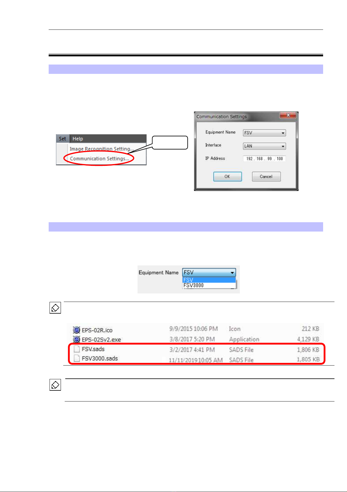
9-3. Communication Settings
Communication Settings Dialog Box
To open the Communication Settings dialog box, click Communication Settings from the Set
menu.
In this dialog box, a remote-controlled spectrum analyzer can be set up.
Equipment Name
Select the equipment name of the connected spectrum analyzer.
The following driver is available as standard options: FSV and FSV3000. Customized spectrum
analyzer drivers are also included in this list.
If the Equipment Name list is blank, no spectrum analyzer driver may exist. Check to see that
spectrum analyzer drivers (*.sads) are stored in the folder where the EPS-02Sv2 executable file is
stored (C:¥Program Files (x86)¥NoiseKen¥EPS-02Sv2, under normal conditions).
When NI-VISA (National Instruments) has not been installed, the Equipment Name list is blank
even if spectrum analyzer drivers exist. In such cases, install NI-VISA according to “10-
3.Installing the Software” in page 35.
Click
9.Operation Procedure
18
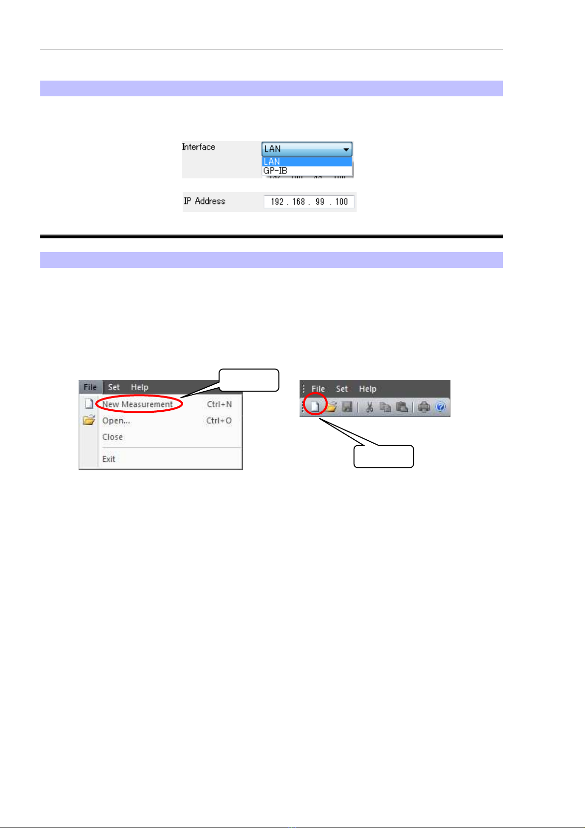
Interface
Select LAN as the interface and set the IP address. For how to set the IP address, see “10-
2.Network Address Settings” in page 34.
9-4. New Measurement (Setting Measurement Conditions)
View Window
To open a View window, click New Measurement from the File menu or click the New
Measurement button on the toolbar.
Whenever a View window is newly opened, it is numbered as follows: View1, View2, View3 ...
These names can be changed freely when the file is saved after measurement.
Before starting measurement, set an image division size, properties for the spectrum analyzer, and
other conditions in the View window.
Click
Click
Table of contents
Other NoiseKen Headlamp manuals


