Nokeval 6821 User manual

1
6821
2 channel transmitter
User manual
2017-01-23
Firmware V1.0-1.6

2
Introduction
The 6821 is a rail-mounted two-channel measurement unit for temperature sensors and other electrical
inputs. The input channels are individual and can be used for different signals. The unit has two analog
outputs or alternatively one analog and one serial output. The serial output accepts Nokeval SCL and
Modbus RTU commands. Up to four logical alarms can control two alarm relays. The inputs are galvanically
isolated from the outputs and the supply voltage, but not from each other.
There are four built-in inter-channel functions: average, difference, minimum, and maximum. More
mathematical and conditional and timed operations may be realized with a simple programming language
called ELo.
The front panel has a four-digit display and four push buttons that can be used to monitor the readings and
to change the settings. The settings can also be edited on a computer using the RS-485 serial connection.
The ELo program can be edited on a personal computer only, not on the front panel.
How to use this manual
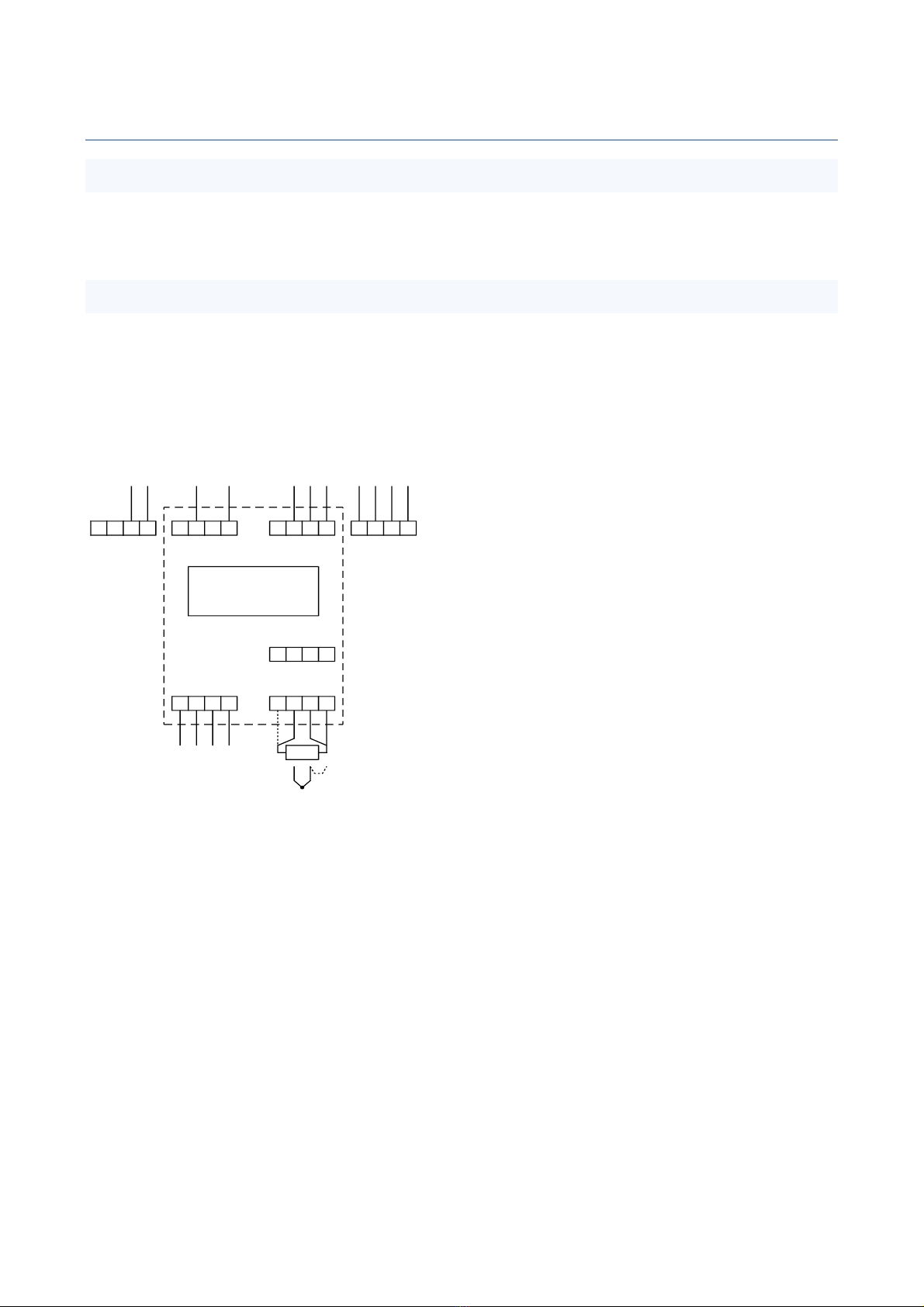
The transmitter consists of several quite independent blocks like the two inputs, analog outputs, serial
communications and so on. That is why this manual is also divided in chapters, one chapter concerning one
block.
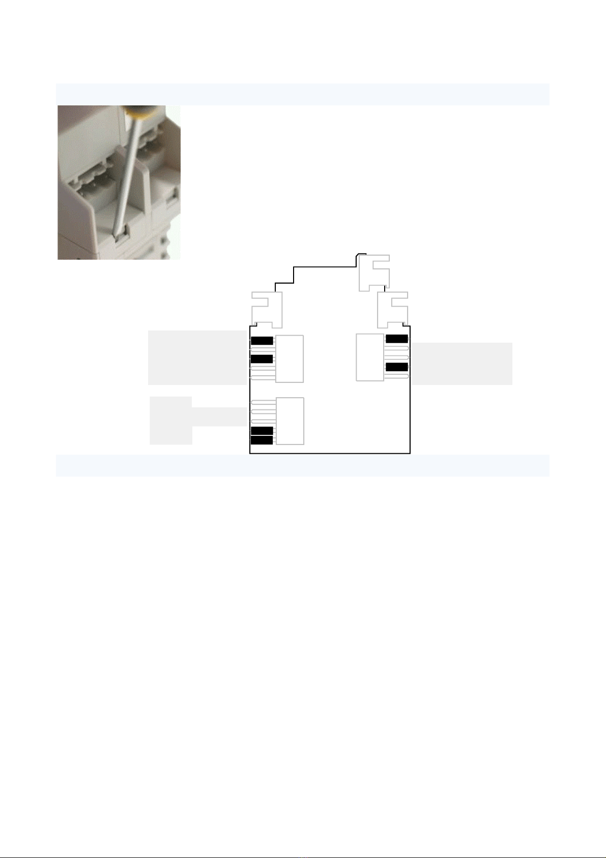
First read through the chapter ”General” to find out how to mount the transmitter and to open the
transmitter case etc and how to get started with the configuration settings, either with the front panel or
with a PC software. Then advance to the chapter ”Power supply”. To get the transmitter to measure
something, read the chapter ”Inputs”. To get an analog output, read the chapter ”Analog output”, and so
on.
Table of contents
Introduction.......................................................................................................................................................2
General ..............................................................................................................................................................3
Power supply .....................................................................................................................................................7
Front panel ........................................................................................................................................................8
Inputs...............................................................................................................................................................12
Analog outputs ................................................................................................................................................17
Alarms and relays ............................................................................................................................................19
ELo program ....................................................................................................................................................21
Serial communications ....................................................................................................................................24
Specifications...................................................................................................................................................31
Manufacturer
Nokeval Oy
Rounionkatu 107
FIN-37150 Nokia
Finland
Tel +358 3 3424800
WWW: www.nokeval.com
Technical support: support@nokeval.com

3
General
Mounting
This transmitter is intended to be mounted on a 35 mm DIN rail. It should be installed on a wall as on the
front cover picture. Other positions will affect the flow of the cooling air and ruin the thermocouple
accuracy. A small air gap to the next instrument on the rail is recommended.
Connections
The connections are explained in the chapters Inputs, Analog outputs, Alarms & relays, Power supply, and
Serial communications.
4 3 2 1
1 2 3 4
4 3 2 1
1 2 3 4
1 2 3 4
6821
85-230 VAC
4 3 2 1
24 VDC/AC
A B
G H
F
Out1
Out Common
Out2
A4 3 2 1
B
Out1
Common
D1 (A+)
D0 (B-)
Power supply Outputs
Relay 1
Relay 2
Alarm relays
Input 1
Input 2
RTD
+
TC, mV, V,
mA

4
Jumpers
To access the jumpers, use a small screwdriver to click the four locks (see
photo). Then pull the top and bottom parts of the case apart. The power
supply must be disconnected to avoid electric shocks.
The picture shows the jumper locations and the default setup. The jumpers
labeled “Free”can be taken off and used where needed.
The jumper positions are explained in the chapters Inputs, Analog outputs,
and Serial communications, pages 12, 17, and 24 respectively.
Configuration settings
There are a plenty of settings that are used to define the operation of the inputs, the outputs, etc. There
are two ways to access them:
On the front panel, see chapter Front panel, page 8.
Using a PC and a serial communications, see chapter Serial communications, section PC configuration,
page 24.
Out1 = mA
Out2 = V
Out2 = mA
Out1 = V
Out2 = 485
Free
485 term
485 floating
Free
Don't use
In1 = mA
In2 pin 1 = +15V
In2 pin 1 = 4W
In2 = mA
Free
See
Analog
outputs
See
Serial
comms
See
Inputs

5
Registers
Analog input x2
In1
In2
Avg
Min
Max
Diff
Built-in functions
Avg
Min
Max
Diff
Analog output x2
@18+=@1
@2>0?2
User program
F1
F2
F3
F12
Serial interface
Scaling Lowpass filter
Alm1
Alm2
Alm3
Alm4
Alarm comparator x4
+
-
Registers
123.4
Display
Relay output x2
OR function
= can be configured to read any
register
Rel1
Rel2
Delay NO/NC
= writes into a register
A1
indicator
Ext1
Ext2
The function blocks of this transmitter –inputs, outputs, etc –are quite independent from each other. The
information between them is exchanged in so called registers. The registers can be seen in the block
diagram above on the gray background. Most of the registers are controlled by some function block. For
example, the register ”In1” is controlled by the first input – there is the input 1 reading.
Registers F1-F12 are controlled by the user program written in the ELo language.
Any register can be used as a ”source” for another block. For example, the analog output 1 can be set to
read the register In1 or any other register. The symbol represents this in the block diagram.
The register values can be viewed with a monitor function, either on the front panel or the PC configuration
program Mekuwin.
Register
Name
Explanation
1
In1
Input 1 scaled reading
2
In2
Input 2 scaled reading

6
3
Avg
Average of the readings, (In1+In2)/2
4
Min
Smaller of the readings In1, In2
5
Max
Greater of the readings
6
Diff
Difference In1-In2
7
Isens
RTD excitation current in mA, normally about 0.25
8
CJ
Internal cold junction temperature in °C
9
Cycle
The measured time to get all the channels, in seconds
10
Out1
Analog output 1 signal in mA or V
11
Out2
Analog output 2 signal in mA or V
12
Alm1
Logical alarm 1 state (0=passive, 1=active)
13
Alm2
Logical alarm 2 state (0=passive, 1=active)
14
Alm3
Logical alarm 3 state (0=passive, 1=active)
15
Alm4
Logical alarm 4 state (0=passive, 1=active)
16
Rel1
Relay 1 state (0=passive, 1=active)
17
Rel2
Relay 2 state (0=passive, 1=active)
18
F1
Free floating point register for ELo programs
19
F2
Free floating point register
20
F3
Free floating point register
21
F4
Free floating point register
22
F5
Free floating point register
23
F6
Free floating point register
24
F7
Free floating point register
25
F8
Free floating point register
26
F9
Free floating point register
27
F10
Free floating point register
28
F11
Free floating point register
29
F12
Free floating point register
30
Ext1
Modbus controlled register
31
Ext2
Modbus controlled register
32
Dch
What to display: 0=Display/Src1, 1=Display/Src1, etc
33
Keys
Front panel key state, see below
Keys register
Keys register gives a sum of the codes of the keys currently pressed:
Key
Code
^
2
v
4
*
8
>
16

7
Power supply
The transmitter 6821 is available for two supply voltage ranges, that are nominally called “24VDC” and
“230VAC”.
6821-24VDC
This model accepts supply voltage of 20 to 28 V DC or AC. The supply is connected in connector A terminals
1 and 2. Either polarity will do.
This transmitter will consume less than 200 mA. However at power-up it will need 500 mA.
6821-230VAC
This model accepts supply voltage of 85 to 260 V DC or AC. The supply is connected in connector A
terminals 1 and 3. The protective earth is not used.
This unit has an internal pre-fuse. If an external one is used, it should be at least 500 mA T.
When wiring, a special attention has to be paid to ensure that accidentally disconnected wires can’t touch
other connectors and cause a risk of an electric hazard. Use e.g. cable ties to group the wires.
4 3 2 1
1 2 3 4
4 3 2 1
1 2 3 4
1 2 3 4
6821
24 V
A B
G H
F
0 V
4 3 2 1
1 2 3 4
4 3 2 1
1 2 3 4
1 2 3 4
6821
230 V
A B
G H
F
0 V

8
Front panel
The front panel can be used to monitor the operation
of the transmitter and to change the settings. It has
several states of operation:
Normal state –displaying the readings.
Configuration state –changing the settings.
Monitor state –displaying the readings and other
variable data.
Normal state
After power-up, the front panel is in the normal state, displaying the input 1 reading (unless otherwise set).
The ”channel” being displayed can be selected using the ^v keys. While changing the channel, the channel
name is displayed until the key is released. Which channels can be selected, depends on the settings
(Display/Src1…4).
The >key can be used to access and change the value of pre-selected registers in order to control the ELo
program (see the Display/Ed settings).
A1 and A2 indicate the states of the alarm relays. They are lit if any of the alarms selected for the relay is
active. The relay NO/NC setting does not affect the indicators.
Configuration state
Entering
Press the *and ^keys simultaneously for two seconds in the normal state to enter the configuration
state. When entered, the Conf led will light. If configuration password is set, it must be entered (Cod.0
displayed). In case the password is not known, switch the power off, hold the *and >keys pressed and
switch the power on again –“PWDC” is displayed briefly. This will also set the serial settings to their default
values.
Navigating
The menu is organized hierarchically. You can move within one menu using the ^v keys and enter a
submenu with the >key. Returning from a submenu is done with the *key. See the menu chart on page
11.
Editing
To see or edit a setting value, press >key.
Most data types are edited simply with ^v keys, finally exiting with *key.
Floating point values, such as scaling and the low pass filter, are edited with ^v> keys: select digit to edit
(blinking) with >and change it with ^v. When the decimal point is blinking, it can be moved with ^v. The
first digit can be replaced by a minus sign.
A1
Conf A2
6800 Series
*
Nokeval
Configuration state
Alarm indicators
Select
Enter
Exit

9
A password is set as follows: push ^to select Set (means password will be used), then push >to enter the
new password. Cod.0 is shown. The password is a sequence of six key presses using all the four keys. Enter
the same password twice; if they match, Set is shown again and you can exit with *. If they didn’t match,
Off is shown. Redo from start. To disable a password, push vto select Off and exit with *.
The math program can’t be edited with the front panel. An RS-485 connection to a computer is required.
Exiting
When all settings are done, exit from the main level of the configuration menu with the *key. Two options
are shown: Save to keep the settings made, and Undo, to discard all changes. Select ^v Save or Undo and
push >.
Monitor state
Monitoring can be used to examine the internal readings, called registers. The built-in monitoring is started
by pressing *and vtogether. Select the item using ^v keys, and finally exit with *.
The registers are explained on page 5.
The last item is Diag. It can be used to see the diagnostic messages. Push >. If nothing happens, then there
are no messages. If happens, try ^v to see if there are several messages. Exit with *.
There are three possible diagnostic messages:
Sensor Fault: some channel has improper connection, over ranging, or a broken sensor or wires.
AD Error: the A/D converter is not working. The unit needs service.
Math Error: there is an error in the math program.
Settings
In the configuration settings menu, there are two submenus concerning the front panel: General, and
Display.
CfCode (General)
This defines a password for the settings. If this is set, the settings can't be accessed without knowing the
password.
To change the password on the front panel, advance to the CfCode setting and push >to edit the value.
Options Off and Set are shown; select Set with the ^v keys. Then push >, and Cod.0 should be displayed.
Now enter six key presses using any of the four keys. Then enter the same sequence another time. If they
matched, Set is displayed again and you can exit with *. Otherwise Off is displayed.
Conf
General
Display
Inputs
Math
Outputs
Alarms
Relays
Serial
General
CfCode
Display
Src1
Dec1
Ed1
Src4
Dec4
Ed4

10
Src1…Src4 (Display)
Display submenu is used to define which readings (or registers) you want to see on the display. Up to four
registers can be selected in Src1..Src4 (the registers are described on page 5). If you do not need all the four
registers, set the rest to Off. After power-up, the register selected in Src1 is displayed, and the others can
be viewed using the ^v keys.
Dec1…Dec4 (Display)
Defines how many digits after the decimal point is displayed on the registers defined in Src1…Src4. Can be
set between -2 and 3. Negative values mean, that the corresponding number of last digits is rounded to
zero. Examples with a reading of 12.34:
Dec=2: ”12.34”
Dec=1: ”12.3”
Dec=0: ”12”
Dec=-1: ”10” (rounded to nearest 10)
Ed1…Ed4 (Display)
If the register selected in Src1 is being displayed, and the user pushes the > key, then the register selected
in Ed1 is displayed and its value can be changed. Likewise while Src2 is displayed, the register selected in
Ed2 can be edited. This way the user can change register values manually and affect the ELo program
operation, control an analog output manually, or quickly adjust the alarm levels.
Other registers than F1…F12 should not be selected in Ed. If the editing is not desired,
set the Ed registers to Off.
When a register value is changed this way, it is stored in the non-volatile EEPROM
memory and restored when the transmitter is powered up next time.
Src1
Src2
Src3
Src4
Ed1
Ed2
Ed3
Ed4
^
v>
>
>
>
*

11
Menu tree
The complete configuration menu is shown here to aid navigating. The menus are explained in the relevant
chapters:
General and Display: page 9.
Inputs: page 15.
Math: page 21.
Outputs: page 17.
Alarms and Relays: page 20.
Serial: page 24.
Conf
General
Display
Inputs
Math
Outputs
Alarms
Relays
Serial
Serial
Protocol
Address
Baud
Parity Relays
Rel1
Rel2
Rel1
Src1
Src2
Src3
Src4
Delay
NC
Alarms
Alm1
Alm2
Alm3
Alm4 Alm1
Type
Src
Level
Hyst
Outputs
Out1
Out2
Out1
Src
Range
Rdg1
Out1
Rdg2
Out2
Math
ELo
Inputs
Common
In1
In2
In1
Sensor
4W
R0
Lopass
Pts
Mea1
Sca1
Mea2
Sca2
Common
Speed
Unit
Differential
Pullup
Display
Src1
Dec1
Ed1
Src4
Dec4
Ed4
General
CfCode
Limit
Break
Dec
ExtLev

12
Inputs
Connections and jumpers
The input signals are connected in connectors F and H: F is the input 1 and H
is the input 2. The connections are illustrated in the next sections.
In addition, jumper settings inside the case might need adjusting. The factory
setting of the jumpers is suitable for all input signals except the mA signal.
In1 = mA: If closed, an internal 50 ohm shunt resistor is connected
between the terminals 2 and 3 to enable the mA measurement on the
input channel 1. The jumper must be open for all the other input signals.
In2 = mA: The same for the input channel 2.
In2 pin1 = 4w: If closed, the terminal H1 will function as a fourth RTD wire on input 2, allowing a four-
wire connection.
In2 pin1 = +15V: If closed, the terminal H1 will provide a 15 V supply for an external transmitter.
Free: These jumper locations are not used, and the jumper may be taken off and used where needed.
RTD and resistance inputs
Three-wire connection: If the sensor has two wires the same color, connect these wires in terminals 3 and
4, and the third wire in terminal 2.
Four-wire connection: Connect the other end of the sensor in terminals 1 and 2, and the other
in terminals 3 and 4. If using input 2, open the case and make sure that the jumper ”In2 pin1”
is set to ”4w”, not ”+15V”, otherwise you might burn your sensor.
Also make sure that the mA jumper is not closed on that input channel.
Thermocouple inputs
Connect the positive wire (K type: green or brown) of the thermocouple in terminal 2, and the negative
(white or blue) in terminal 3. If the wires are long, it is also advisable to link the terminals 3
and 4 together.
If you have two thermocouples and they are electrically connected to each other (mounted on
the same metallic object), then use the 3-to-4 link on the other channel only, so that the other
one is a fully differential input.
Make sure that the mA jumper is not closed on that channel.
Voltage inputs
Connect the positive wire in terminal 2, and the negative wire in terminal 3. If the wires are
long, it is also advisable to link the terminals 3 and 4 together.
Make sure that the mA jumper is not closed on that channel.
Current inputs
Connect the positive wire in terminal 2, and the negative wire in terminal 3. If the wires are
long, it is also advisable to link the terminals 3 and 4 together.
4 3 2 1
1 2 3 4
4 3 2 1
1 2 3 4
6821
A B
G H
F
1 2 3 4
1 2 3 4
RTD
+
Tc
1 2 3 4
+
mV
1 2 3 4
+
mA
1 2 3 4

13
Close the mA jumper on that channel.
Transmitter supply
This transmitter can provide a 15 V 50 mA supply for an external transmitter. This voltage is output at
connector H terminal 1 (+) and terminal 4 (ground). To switch on the voltage supply, the jumper “In2 pin1 =
+15V” has to be closed and the jumper “In2 pin1 = 4w” opened. After this, an RTD in four-wire connection
must not be connected in connector H, otherwise it will get 15 volts and probably get damaged.
The picture shows an example of connecting two external 2-wire transmitters to this transmitter. Terminal
H pin 1 provides the 15 V supply for the transmitters. The current is returned to the terminal 2, which is the
positive mA input. The current passes the internal shunt resistor and comes out of the terminal 3, which
must be connected to terminal 4 to allow the current to return to the internal ground.
Potential equalization
The input circuitry is galvanically isolated from the power supply and output circuits. However the input
channels are not isolated from each other. Moreover there is a differential amplifier in each input that
requires that the potential of the inputs (terminals 2 and 3) is near the input circuitry ground (terminal 4).
With RTD's, the differential amplifier input is tied to the input ground via the sensor connections and there
is no matter. With the other inputs, the differential amplifier input must be tied to the internal ground
somehow. There are three different ways:
Internal grounding switch
The input terminals 2 and 3 are connected through
semiconductor switches to the differential amplifier feeding the
analog-to-digital converter. The other channel is separated by
open semiconductor switches. In the picture a thermocouple is
connected on the both channels as an example. There is no
external connection in the terminal 4, the input ground.
The internal grounding switch is enabled by setting Differential to
No in the Inputs / Common menu. This switch will pull the input
circuitry ground potential to the negative line potential on the
channel being measured.
The potential of the other input can be several volts different than this channel, since it is separated by the
switches. However the switches will not tolerate infinitely voltage. The rule is that the both lines (+ and -) of
an input must be within 10 V in respect to the negative line of the other input. A difference of more than 30
V may damage the inputs.
1 2 3 4
1 2 3 4
2w
2w
+15V
Gnd
Internal
mA shunt
1
2
3
4
1
2
3
4
x
Diff. amp
In1
In2
Gnd
sw
+
-
+
-+
-
Input gnd

14
This is the easiest way to connect, and the only that will allow several volts between the negative lines of
the inputs.
External linking
If the input sensors are galvanically isolated from each other, then it
is recommended to tie them both to the input circuitry ground.
Connect a piece of wire between the terminals 3 and 4. This ties
them to each other too.
It does not matter if the internal grounding switch is open or closed,
since the differential amplifier negative input is externally tied to the
input ground. So the Differential setting in Inputs / Common can be in any position.
This connection method will give the best performance against disturbances and overvoltage.
Other external path
The potential equalization does not have to be a link on the terminals –it can be a longer path as far as it
keeps the potential between terminals 3 and 4 small enough. If an external path exists, then it is best to
open the internal grounding switch by setting the Differential setting to On in the Inputs / Common menu.
An example of this could be a voltage-output three-wire
transmitter. If it is connected with three wires, the
lowest wire will have two purposes: it is both the return
of the supply current and the negative signal wire. The
return current will cause a voltage difference between
the wire ends, making an error in the voltage signal. This
can be avoided by using separate wires for the supply
current return and the signal, as in the picture. The
differential amplifier measures the voltage between terminals 2 and 3 using the wires carrying no current.
The differential amplifier inputs (terminals 2 and 3) can tolerate voltage in respect to terminal 4 as follows:
mV and Tc ranges: -0.15…+0.95 V both.
1 and 2.5V and mA ranges: -2…+4 V both.
10 V range: negative terminal ±1 V, positive -6…+11 V.
Another example of the external path: Two thermocouples connected to the same metal object. In this
case, the negative wires are not allowed to be connected together at the transmitter terminals. The link
between terminals 3 and 4 can’t be used. Instead, have the link on the other input only –it will keep the
differential amplifier inputs near ground on both inputs.
Operation
Several analogue switches are used to connect the A/D converter and the sensor current supplies to the
channel being measured. In addition to the two external channels, there are two internal channels: the cold
junction temperature (for thermocouples) and the RTD excitation current measurement.
The result is processed according to the sensor type selected. For the temperature sensors, a temperature
reading in °C or °F is obtained; for other input types, a mV/V/mA reading is obtained. This transmitter
provides a possibility for a free two-point scaling. It can be used to cancel sensor errors or to convert the
input signal to “engineering units”. A first-order low pass filter can be applied to remove noise and
disturbances.
1
2
3
4
+
-
Link
x
Diff. amp
Gnd
sw
+
-
1
2
3
4
+
- x
Diff. amp
Gnd
sw
+
-
3-wire
transmitter +15V
0-10V

15
Conf
General
Display
Inputs
Math
Outputs
Alarms
Relays
Serial
Inputs
Common
In1
In2
In1
Sensor
4W
R0
Lopass
Pts
Mea1
Sca1
Mea2
Sca2
Common
Speed
Unit
Differential
Pullup
This transmitter calculates always four inter-channel readings: the average, the smaller, the greater, and
the difference of the inputs.
Fault detection
If the transmitter finds the sensor faulty, the corresponding In1 or In2 register will be set to a NaN (not-a-
number) value to indicate an exception. An analog output configured to follow that register will then
indicate fault by going to a maximum value. Every logical alarm following the In1 or In2 register will
activate.
If either sensor is faulty, the Diff and Avg registers will also go to NaN. The Min and Max registers will
ignore the faulty channel, but if both of the inputs are faulty, then Min will go to 100000 and Max to -
100000.
Settings
The configuration menu is divided in several submenus.
The input settings are in a submenu called Inputs, which
is further divided in Common, In1, and In2 submenus.
In1 and In2 submenus are identical.
Speed (Common)
Measurement speed selection. ”Normal” speed is
intended for normal use, and the specifications are valid
for that. The higher speeds will increase noise. The
“Slow” speed can be used, when increased accuracy is
needed.
Unit (Common)
Measurement unit with thermocouple and Pt/Ni/Cu/KTY83 sensors. °C or °F.
Differential (Common)
Internal grounding of the differential inputs. Not applicable to resistance inputs, like Pt100.
This is discussed in detail on page 13.
No: The transmitter uses a semiconductor switch to ground the negative terminal of the channel being
measured.
Yes: The inputs are differential (or floating), and the potential equalisation must be done externally.
Pullup (Common)
Sensor/wire break sensing. If enabled, a weak current (1.5 µA) is fed to the thermocouple sensor to detect
faults.
Sensor (In1, In2)
Input range and sensor selection.
Off: Channel not used. It is recommended to set unused channels to off, in order to speed up the
measurement cycle.
55mV, 100mV, 1V, 2.5V, and 10V: Voltage inputs. Can measure negative voltage too, however the 2.5V
range reaches only -1 V. The reading is in millivolts or volts according to the name of the range.
20mA and 50mA: Current inputs. Can measure also negative current. The appropriate jumper inside the
case has to be closed.

16
400ohm, 4000ohm, and 40000ohm: Resistance inputs. The resistor is connected in three-wire or four-
wire connection. The reading is in ohms.
Pt, Ni, Cu, and KTY83: Resistance thermometers (RTD's). The nominal resistance is set in R0 (see below).
The reading is in Celsius or Fahrenheits.
TcB-TcT: Thermocouples. The result is in Celsius or Fahrenheits.
4W (In1, In2)
RTD connection mode. Visible on the RTD and ohm inputs only.
No: Three-wire RTD connection.
Yes: Four-wire RTD connection.
R0 (In1, In2)
The nominal resistance of an RTD. With Pt and Ni sensors, this is the resistance at 0°C. With a Pt100 set
R0=100. With Cu and KTY83, the nominal resistance is given at 25°C. This setting is not visible on other than
RTD inputs.
If the real, calibrated resistance of the sensor at the nominal temperature is known, it can be fed here, in
order to cancel the sensor error.
Lopass (In1, In2)
First-order lowpass filter for the reading. Attenuates noise and disturbances. Set the time constant (to 63%
of step change) in seconds, or 0 to disable.
Pts (In1, In2)
Number of the scaling points. The scaling means converting the reading to represent some other
(engineering) reading. The scaled value is used on the display, serial output, analog outputs, and alarms.
0: No scaling.
1: One point offset correction. The reading corresponding to Mea1 is scaled to be Sca1 when displayed,
using appropriate offset value.
2: Two point scaling. Readings from Mea1 to Mea2 are scaled to be Sca1 to Sca2. Any values can be
used, these have not to be the end points.
Mea1, Sca1, Mea2, and Sca2 (In1, In2)
Scaling points. Visibility of these settings depends on the Pts setting. Unscaled reading Mea1 is converted
to Sca1, and Mea2 to Sca2.
These scaling points can be conveniently used to calibrate a sensor-transmitter pair in a thermal bath. First
set the scaling off by setting Pts=0. Apply one or two known temperatures to the sensor and write down
the displayed and the real temperatures. Then set Pts to 1 or 2 depending on the number of calibration
points, and write the first reading in Mea1 and the real temperature in Sca1. And the same with Mea2 and
Sca2 if two points are to be calibrated.

17
Analog outputs
Connections and jumpers
The two analog outputs are provided in the connector B.
There are five jumpers affecting the analog outputs. The first output Out1 can be selected among the mA
and V output signals –the corresponding change must be done in the configuration settings too.
The second output can be selected among mA, V, or RS-485 serial outputs.
The factory setting is two mA outputs and no serial communications.
Operation
The analog output can be programmed to follow either input, any built-in function, or any register including
the results of an ELo program. A free two-point scaling is provided to convert the reading to a physical
signal in mA or V.
When the output is configured to follow an input (e.g. the In1 register) and the sensor is broken, the output
will indicate fault as defined by the Break setting. Technically, when the register value is a NaN, the output
will indicate fault.
Settings
The Outputs submenu is further divided in two
identical submenus, Out1 and Out2 for two analog
output channels.
Src
The register that the output is taken from. If you
want this output to follow the input 1 reading,
select In1. If you want to follow the difference In1-
In2, select Diff etc. More about the registers on the
page 5.
4 3 2 1
1 2 3 4
4 3 2 1
1 2 3 4
1 2 3 4
6821
A B
G H
F
Out1
Common
Out2
Out1 = mA
Out2 = V
Out2 = mA
Out1 = V
Out2 = 485
Free
Free
Free
Conf
General
Display
Inputs
Math
Outputs
Alarms
Relays
Serial
Outputs
Out1
Out2
Out1
Src
Range
Rdg1
Out1
Rdg2
Out2

18
Range
Analog output range mA or V. The jumpers inside have to be set correspondingly.
Rdg1, Out1, Rdg2, and Out2
Output scaling. The reading Rdg1 corresponds to the output signal Out1 (in mA or V), and Rdg2 to Out2.
These have not to be the end points, since the transmitter is able to extrapolate.
Example: Reading 0-6 (bar) is wanted to give output of 4-20 mA. Settings:
Range = mA
Rdg1 = 0 (bar)
Out1 = 4 (mA)
Rdg2 = 6 (bar)
Out2 = 20 (mA)
Limit
Yes: The output is limited between Out1 and Out2 and will not overrange.
No: The output is not limited and will overrange as much as it physically can.
This setting does not affect during a fault; the Break setting overrides this. Available in firmware V1.5 and
newer; V1.0-1.4 will not limit.
Break
The output behavior when the source is indicating fault (NaN), e.g. when the sensor is faulty. Available in
firmware V1.5 and newer; V1.0-1.4 will behave according to the Max option.
Min: The output will go to 0 mA or 0 V.
NamurLo: The output will go to 3.5 mA.
Out1: The output will go to Out1, i.e. the low end of the scaled range.
Out2: The output will go to Out2.
Max: The output will go to its maximum value, approx. 22.5 mA or 11 V.

19
Alarms and relays
Connections
There are two alarm relays inside the transmitter. The contacts of the first
relay are connected in connector G terminals 1 and 2, and the second relay in
terminals 3 and 4. These have no internal connection elsewhere: they are
“potential free”.
The relays can be used to control a 230 VAC line voltage. If one relay is
connected to the line voltage, then the other must not be used for SELV
circuits for electrical safety reasons.
When there are line voltages present, the wires must be tied e.g. with cable
ties so that an accidentally disconnected wire can’t cause a hazard.
Controlling a heavily inductive load will shorten the life of the relays. An
external snubber circuit or a varistor is then recommended.
When this unit has no power supply, the relay 2 contacts will be closed and relay 1 contacts open.
Operation
There are four independent logical alarm comparators that are used to examine a single register (e.g. the
input 2 reading) whether it is above or below a limit. The result is either “false” (0) or “true” (1). These do
not control any relay yet.
After the logical alarms have been configured, the relays can be programmed to follow those logical alarms.
Up to four logical alarms can be defined for a relay. If any of them is “true”, the relay will activate.
The relays have a NO/NC (normally open/closed) selection. It affects the relay coil only. The front panel
indicators A1 and A2 tell whether the relay is active, that is if any of the logical alarms selected is ”true” and
the delay has expired, but are not affected by the NO/NC selection.
When the register selected for the logical alarm has a NaN value (Not-a-number used to express a fault),
the logical alarm will always be “true”. In practice, if the sensor fails, all the associated alarms will activate.
4 3 2 1
1 2 3 4
4 3 2 1
1 2 3 4
1 2 3 4
6821
A B
G H
F
Relay 1
Relay 2

20
Alarm settings
There are four identical logical alarms, one in each
Alm1…Alm4 submenu. The first alarm controls the
register Alm1 and so on. The relays following these
alarms are set up in the Rel1 and Rel2 submenus.
Type (Alarms/Alm1…Alm4)
Alarm type:
Off: This alarm is not used.
Lo: Low level alarm. Activates if the reading
specified in the Src setting goes below the Level
setting.
Hi: High level alarm.
Src (Alarms/Alm1…Alm4)
This defines the register that this alarm investigates. E.g. to have a high level alarm when the input 1
exceeds 50, select Src=In1 and Level=50.
ExtLev (Alarms/Alm1…Alm4)
To have the alarm level “externally”controlled, select the controlling register here. Select one of the
F1…F12 registers along with the “Edit”option to have a quickly adjustable alarm level. The selected register
value will be summed with the Level setting to form the final level. To have a simple fixed alarm level,
defined by the Level setting, set this setting to Off. Available from firmware version V1.6 onwards.
Level (Alarms/Alm1…Alm4)
Alarm level. The alarm will activate when the reading goes past this limit.
Hyst (Alarms/Alm1…Alm4)
Alarm hysteresis. When the alarm has activated, the reading must come an amount defined here back from
the Level to be deactivated. E.g. if Level=50 and Hyst=5 and Type=Hi, the alarm will activate at 50 and
deactivate at 45. Always positive.
Relay settings
Src1…Src4 (Relays / Rel1…Rel2)
Sources for one relay. Select up to four registers that are examined. If any of them has a positive value, this
relay is activated. Normally these are one of Alm1…Alm4 registers or Off. Example: If you want this relay to
pull when Alarm 1 is activated, select Src1=Alm1 and rest of Srcs Off.
Delay (Relays / Rel1…Rel2)
Activation and deactivation delay. An alarm must be continuously active for the time specified in Delay in
order to cause a real, common alarm.
The delay time is given in seconds. The maximum delay time is 3495 seconds.
NC (Relays / Rel1…Rel2)
Inverting the relay operation. Affects only the relay coil, but not the LED indicators A1 and A2.
No: Normal operation, normally open: the relay pulls when an alarm is active.
Yes: Inverse operation, normally closed: the relay releases when an alarm is active.
Conf
General
Display
Inputs
Math
Outputs
Alarms
Relays
Serial
Relays
Rel1
Rel2
Rel1
Src1
Src2
Src3
Src4
Delay
NC
Alarms
Alm1
Alm2
Alm3
Alm4
Alm1
Type
Src
Level
Hyst
Table of contents
Other Nokeval Transmitter manuals
Popular Transmitter manuals by other brands

Kimo
Kimo C310 user manual

GreenTech
GreenTech RD2690 Series Programming menu

TRUEYES
TRUEYES Air-Q TT300 user manual

Linear
Linear DXS-32/EC installation instructions

Capetti Elettronica
Capetti Elettronica Winecap PA-DPS-83 50 user manual

HK Instruments
HK Instruments DPT-Flow Series installation instructions

Electron-Sky
Electron-Sky CZH-05A user guide

Critical Environment Technologies
Critical Environment Technologies cGas Detector Operation manual

Rice Lake
Rice Lake SCT-1SX-Ethernet/IP quick start guide

Celec
Celec LTR7000 User's & technical manual

Rice Lake
Rice Lake SCT-1SX-PROFINET quick start guide

Chamberlain
Chamberlain LiftMaster 61LM manual