Nokeval Kube-Sky-RHT-P-CO2-PIDVOC User manual

ID9727 V1 19.6.2018
Firmware 1.0-1.0
Kube-Sky-RHT -P -CO2 -PIDVOC
Manual

2 - Introduction
Contents
Introduction....................................................................................................................................................2
Installation......................................................................................................................................................3
Maintenance ...................................................................................................................................................8
Specifications..................................................................................................................................................9
Warnings .......................................................................................................................................................10
Manufacturer ................................................................................................................................................10
Introduction
The Kube-Sky-RHT series consists of several models of wireless indoor air quality transmitters. All models
have a LoRa based Nokeval Sky radio with a very good range.
Models
The Kube-Sky-RHT is the basic model. It measures temperature and humidity only. With moderate
settings, the battery life will exceed five years.
When the model name has a –CO2 suffix, the device also measures carbon dioxide concentration up to
5000 ppm. This model needs to see fresh air at least once a week to be able to auto calibrate itself.
This model is not suitable for premises that are continuously occupied; such premises result carbon
dioxide measurement to show smaller values than should. The CO2 model can be used with batteries,
however the battery life will be significantly shorter. An external power supply can be used to overcome
this.
The model with -PIDVOC suffix has a high quality photoionization detector for detecting volatile organic
compounds. The sensor is factory calibrated, and it can operate in a continuous exposure unlike many
sensors that will auto-zero themselves. The sensitivity goes to tens of ppb. This model must be powered
with an external supply.
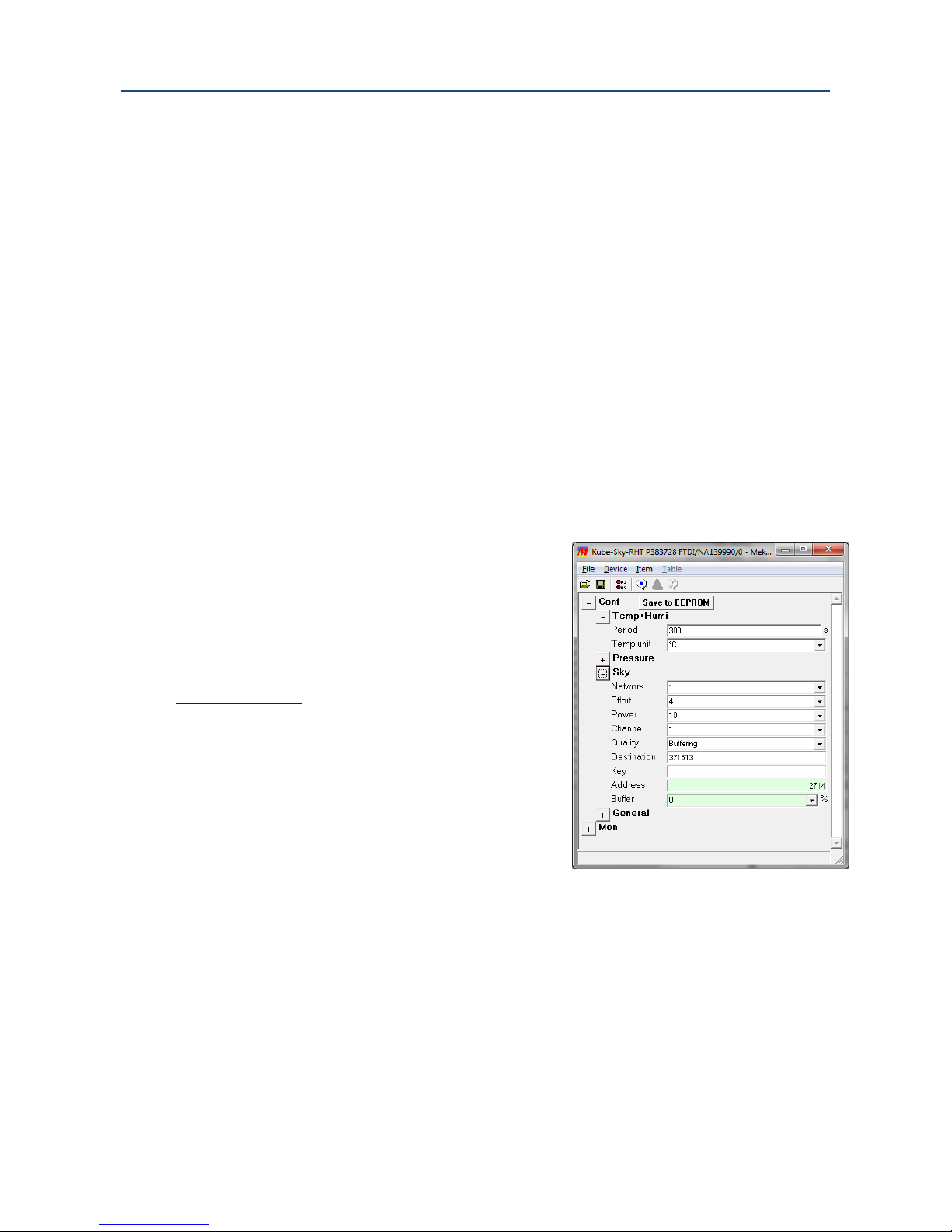
Sky radio
The Sky devices use the Semtech LoRa modulation technique that allows unforeseen wireless range in a
battery powered transmitter. The protocol used is defined by Nokeval, called Sky, which means that this
device is not compatible with the LoRaWAN infrastructure.
The modulation has some parameters to define its operation. With the “maximal” settings, a very long
range can be reached, but at the expense of high battery and radio band consumption. One radio
transmission can last approx. 2 seconds (compared to 20 ms of the Nokeval MTR series). This means that
the number of transmitters within the range must be limited in order to avoid collisions and to allow
radio time for each. It is not practical to use a short interval between transmissions; 10 to 30 minutes is
the recommended interval range.
When the maximal range is not necessary, the parameters must be adjusted for lower battery and band
consumption. All the devices within one network must share the parameters, because the receiver can
only listen with one set of parameters at a time. Consequently the parameters must be selected
according to the most distant device. It is also possible to adjust the transmission power. The devices
that are closer to the receiver can use a lower power setting.
Before using the 433 MHz radio, make sure it is legal in your country.

3 - Installation
Installation
Attachment
Attach the device to the measuring location with one of the following ways:
•Mount the Kube wall holder to a wall with two countersunk head screws, with its hooks pointing
upwards, and snap the transmitter to it.
•Set the Kube standing on a shelf, on top of a cabinet or some other suitable surface. Attach the
provided self-adhesive bumpers to the bottom (the slim RHT only model may not be supplied
with the bumpers).
Power supply
The RHT and -CO2 models come with batteries installed, ready to be used.
If you are to supply the device with a USB charger, plug one to the micro USB connector at the bottom of
the device. A 500 mA charger is more than sufficient. The indicator LED will light shortly.
Alternatively, an external 5 V DC supply can be connected to the round holes of the push-in spring
connector J11 with 0.2-0.5 mm2conductors, the positive wire to the left. Strip the wires approximately 6
mm. The cables can be detached by pushing a small flat screwdriver or some other spike to the
rectangular holes.
To check that the device is powered, push the button once and check that the indicator LED lights.
Configuration
The device works with its default settings, but you can change
the settings if needed:
•Connect a Micro-USB-B cable to the connector, and the
other end of the cable to a computer.
•If Windows requests for a driver, download it at
www.nokeval.com > Support, unzip it to a temporary
folder, and show that directory as the location for the
driver.
•Launch the Mekuwin program (available for free at
www.nokeval.com).
•In Mekuwin, choose Port=Kube (COMxx),
Protocol=Modbus, Address=1. Click Direct.
•A new window will open. It has branches for different
configurations.

4 - Installation
Menu chart
This is the configuration menu of firmware V1.0. The different versions may have slight differences and
lacking features. The menu is divided to submenus for each quantity group. In addition to those, it has a
submenu for the wireless network settings and another submenu for general settings.
Conf
Temp+Humi
Pressure
Gases
Particles
Sky
General
General
Code
Sky
Network
Effort
Power
Channel
Quality
Destination
Key
Address
Buffer[%]
Gases
Period[s]
CO2
VOC
VOC
Warmup
Sampling time
Coefficient
CO2
Sampling time
Autocal
Manucal
Manucal
Level
Now
Autocal
Period[h]
Base level
Max adjust
Time[h]
Temp+Humi
Period[s]
Temp unit
Sensor menu settings
Period
This setting determines the measuring and transmitting period of the various quantity groups, such as
gases, particles, or pressure. Temperature and humidity form one group. The allowed range is 5…7200
seconds. This setting has strong impact on the battery life. Avoid using too short periods, because it will
cause faster battery exhaustion. By setting the period to value 0, the measurement is turned off.
The default is 300 for temperature, humidity and lux, and 1800 for gases and particles.
Temp unit
Temperature unit °C or °F.
Gases-> CO2 -> Sampling time
This setting determines how many seconds CO2concentration is measured. The bigger the value, the less
noisy reading, but the battery is exhausted faster. A good value is 30 seconds when externally powered,
or 15 for battery power.
Gases-> CO2 -> Autocal -> Period (h)
This setting determines how many hours passes before the device performs an auto calibration. A good
period setting is 192 hours which is a little more than a week as the device timer is not accurate.
Gases-> CO2 -> Autocal -> Base level
The device looks for the lowest reading from the period and if that differs from this setting, the device
adjusts the future measurement readings down or up as needed. This is what the auto calibration means.
The base level is typically 400, which is the clean air concentration or a little more.
Gases-> CO2 -> Autocal -> Max adjust
This setting limits the maximum adjust that is done at a time. Good value is 50.

5 - Installation
Gases-> CO2 -> Manucal
This allows manually calibrating the CO2 offset. Enter the real CO2 level and press the Now button. Wait
for a moment.
Radio settings
The Sky menu contains the settings for the wireless network.
Network: To prevent mixing the different networks (and users) data, the network address should be set
to some value not used nearby. In most cases a random value 1 to 255 is OK. All the devices within one
network must share the value. The receiver will only accept packets that have the matching network
address. If an encryption key is used, it is not necessary to use an unique network address as the
encryption itself will prevent the networks from mixing. Default 1.
Effort: The modulation effort. The bigger value, the longer range but the more battery and radio band
consumption. This single setting controls the LoRa bandwidth and spreading parameters as in the table
below. Increasing the effort one step will coarsely add 2.5 dB in the link budget, or 30% of open-space
range, but also double the battery consumption caused by the radio.
The range estimates are only estimates, the real range depends heavily on objects on the radio path.
Especially metal walls will severely attenuate the radio waves.
Effort setting
Bandwidth
Spreading
factor
Estimated indoor range
40...35 dB/decade
Estimated outdoor range
30 dB/decade
1
250 kHz
7
90...260 m
1100 m
2
250 kHz
8
100...300 m
1300 m
3
250 kHz
9
120...360 m
1600 m
4
250 kHz
10
140...420 m
1900 m
5
250 kHz
11
160...500 m
2300 m
6
250 kHz
12
180...590 m
2800 m
7
125 kHz
12
220...720 m
3500 m
The default Effort is 4, which is good for many tasks. Each device in the network must share the value.
The Effort setting can be set to Custom position; then it is possible to set the bandwidth and spreading
parameters independently, as well as adjust the frequency steplessly within 433.3 to 434.5 MHz. Normally
this should not be necessary.
Power: The transmission power; 10 means the maximum power and each step reduces one dB. A lower
value should be selected to conserve battery and to avoid disturbing other users of the band whenever
possible. However this setting will not affect the battery consumption as much as the Effort setting,
which means that the first mean to lower the battery consumption should be lowering the effort if
possible. While each device in the network must share the Effort setting, the Power can be adjusted
individually. In practice, the Effort is defined by the most distant device, and the Power of the nearer
devices can be lowered.
Channel: The radio frequency channel. If several LoRa/Sky networks exists within the same area, a
different frequency should be selected for each network. The radio frequency is 433.3 + 0.2 MHz *
(channel-1), i.e. the first channel is 433.3 MHz, second 433.5 etc. When using Efforts below 7 (bandwidth
of 250 kHz), the nearby networks (systems) should have channels of at least two steps apart, e.g. 1 and 3
to avoid overlap. The channel 4 uses 433.9 MHz which is the most crowded frequency on this band, so it
should be avoided. To sum up, good channels are 1, 3, 5, and 7. Each device must use the same channel.
Quality: This setting has three options affecting the reliability of the packet delivery:
•Unidirectional: This device will transmit each reading once not expecting any acknowledgement.
If the packet is lost due to a collision with another transmission or any disturbance, it is lost.

6 - Installation
•Bidirectional: After transmitting a packet, this device will listen for an acknowledgement from a
receiver and retransmit up to two times if not getting acknowledged. If there is no
acknowledgement, this device will discard the packet and try only once for the next time. This
setting increases the probability of successful delivery significantly but does not guarantee it.
•Buffering: This device will keep retransmitting each reading until acknowledged. The readings
will be buffered until delivered as far as the buffer is not full. The buffer can hold approx 400
packets. When the buffer is more than half full, the measurement intervals will be temporarily
increased to slow down the filling of the buffer.
Each device can have an individual choice.
Destination: When using the Bidirectional or the Buffered quality, the receiver that is supposed to
acknowledge must be manually defined. Enter the radio address of the receiver here. The system can
have several receivers, each picking the same radio packets, but only one can acknowledge to avoid
collisions.
Key: An authentication and encryption key for the radio. If an authentication is not desired, leave this
blank. Then it is quite easy to eavesdrop and disrupt the radio traffic. To get a secured operation, enter
any text string (up to 16 characters). Use the same key in the receiver, and consequently in all the other
transmitters.
Address: The radio address of this device. Can’t be changed here.
Buffer: How many percents of the buffer is used. Should be 0 when the network is operating smoothly.
Other settings
General -> Code
If a password (six letters or digits) is entered here, the same password has to be known when next time
accessing the settings.
Monitor menu
In the mon(itor) menu, you can watch the measurement readings.
Temperature: The temperature reading in °C.
Humidity: The relative humidity reading in %RH.
Lux: The illumination reading in lx.
Barometer: The air pressure reading. The feature is not yet in use.
CO2: The carbon dioxide concentration in ppm.
VOC: The volatile organic compound measurement reading in ppm. The feature is not yet in use.
Batt: The estimated remaining battery capacity in percents.
ExtPow: Is an external power supply connected.
Switches: The button status for the manufacturer’s testing.
Cal menu
The calibration menu settings are only for the manufacturer use, and they are not explained in this
manual.
Quantity channels
The device sends the measurement data with its device address using the channels as follows:

7 - Installation
Channel
Physical quantity
Unit
1
Temperature
°C or °F
2
Relative humidity
%RH
4
Absolute air pressure
mbar
5
Carbon dioxide concentration
ppm
6
Volatile organic compound conc.
ppm
7
Differential pressure
Pa
21
PM1 particulate matter
µg/m3
22
PM2.5 particulate matter
µg/m3
23
PM10 particulate matter
µg/m3
24
40µm particulate matter
These channel numbers are used when configuring the device for the Ovaport service or any other type
of receiving system.

8 - Maintenance
Maintenance
Not used for a while
If the device is not used for months, it is recommended to remove at least one battery.
Checking the status
Now and then, it is advisable to press the button to light up the indicator located next to the USB
connector. If it lights green, everything is fine. If the indicator blinks red, count the number of blinks and
compare to the table below.
Red blinks
Meaning
What to do
2
Battery low
Replace the batteries soon.
3
Radio error –the radio is not operating
Send the device for repair.
4
Network error –the device is not
acknowledged by the receiver
Check that the Sky settings match the
receiver (also the Destination), and that the
receiver is operating and not too far away.
5
Internal A/D converter failure
Send the device for repair.
6
Temperature/humidity sensor failure
Send the device for repair.
7
Absolute pressure sensor failure
Send the device for repair.
8
Absolute pressure sensor failure
Send the device for repair.
9
Sensor module failure (CO2, VOC etc)
Send the device for repair.
If the indicator doesn’t light up at all, the device is not operating, probably due to a lacking power.
Active state
By pressing the button twice, the device goes for 15 minutes to an active state, where it lights the
indicator continuously and sends the measurement readings frequently, e.g. the temperature and
humidity at every 15 seconds. This may be useful when troubleshooting the system.
Press the button once to exit this state. Even without pressing the button, the device will return to the
normal state in 15 minutes.
Changing the batteries
•Remove the device from the wall holder where applicable by pushing it upwards.
•Remove the two PZ1 screws and open the cover.
•Replace the batteries with two new LR6 (alkaline AA) batteries observing the polarity. Avoid
touching the electronics.
Cleaning
If there is visible dust inside the device, blow it away periodically with pressurized air while avoiding too
strong pressure.
The enclosure exterior can be wiped with a damp cloth soaked in soap or isopropanol, but no drop of
liquid must enter the device.
Recalibration
Temperature and humidity: These sensors do not normally need recalibration, but can be checked if
desired.
CO2: This sensor does not normally need recalibration. Its gain is quite stable, while the offset (baseline)
is automatically calibrated weekly.
VOC: This sensor may need periodic recalibration and service. The more dirty environment, the more
often. Once per year is a good starting point.

9 - Specifications
Specifications
Environment
Storage temperature -30...+60 °C, non-condensing
Operation temperature 0...+60 °C
Operation humidity 5...95 %RH, non-condensing
Protection class IP20
Enclosure material Plastic (ABS+PC)
Measurements
Weight RHT: 130 g
RHT-P-CO2: 140 g with batteries
RHT-PIDVOC: TBD
Dimensions Width: 75 mm
Height: 95 mm
Depth: RHT 28 mm, -CO2 and -VOC 48 mm, including the wall mount
Internal batteries
Type LR6 (AA 1.5 V alkaline). For the advertized battery life, a high quality battery should be
used, e.g. Energizer EN91
Battery life
External supply USB
Connector Micro USB Type B 5 V 100 mA, no suspend function
External supply with a cable
Connector Push-in spring connector for 0.2-0.5 mm2conductors
Voltage 5 V ±0.5 V
Consumption Average about 5 mA, momentarily max 100 mA
Sky radio
Antenna Internal
Center frequency 433.3…434.5 MHz user adjustable
Bandwidth max 300 kHz OBW
Transmitting power max 10 dBm E.I.R.P.
Open space range about 10 km with maximal parameters
Indoor range 150 to 500 m typically
Temperature measurement
Measurement range -20…+50 °C
Accuracy ±0,5 °C in the range of +10...+50 °C
Step response time TBD (63 % of a step change)
Humidity measurement
Measurement range 0…100 %RH non-condensing
Accuracy ±3 %RH with humidity of 20…80 %RH and temperature of +10…+50 °C
Carbon dioxide concentration
Measurement range 0…5000 ppm
Accuracy ±50 ppm + 3% of the reading
Autocalibration Must see fresh air once a week
Volatile organic compound concentration
Measurement range 0…10 ppm isobutylene
Accuracy ±50 ppb + 10% of the reading
Autocalibration No autocalibration, must be periodically recalibrated and serviced
Nominal gas Isobutylene C4H8
Coefficient for toluene 0.56 (multiply the Kube reading by this if you know the gas is toluene)
Coefficients for other List available separately

10 - Warnings
Warnings
The device must not be disposed of in household waste. Observe local regulations
concerning the disposal of electrical waste. The device contains a battery.
Manufacturer
Nokeval Oy
Rounionkatu 107
FI-37150 Nokia
Finland
Phone +358 3 342 4800 (Mon-Fri 8:30-16:00 EET)
WWW http://www.nokeval.com/
Email support@nokeval.com
Table of contents
Other Nokeval Transmitter manuals
Popular Transmitter manuals by other brands

Wave Central
Wave Central AXIS TX PICO PLUS Menu information

Novus
Novus TXMINI-M12-485 operating manual

Farpointe Data
Farpointe Data RANGER WRT-2+ quick start guide

HumanTechnik
HumanTechnik RadioLight operating instructions

Honeywell
Honeywell 5878 - Wireless Wall Transmitter user guide

Inovonics
Inovonics ShatterPro EE1247 Installation and operation